S86E Implementation Cookbook V1.1


Installation and Device Management
1.1 System Management
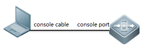
1.1.1 Console Management
 .
.
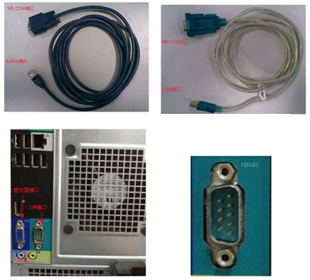
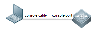
l Cables
consolecable , USB to RS232 cable
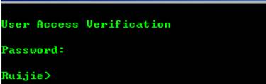
l loginthe device
Openyour software Putty, set baud rate to 9600
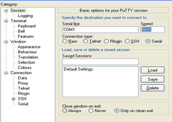
After systemprompts "Ruijie>", you can start your configuration
1.1.2 Telnet Management
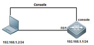
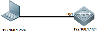
I. Network Topology
II. ConfigurationSteps
1. console connect todevice and set passwords
2. set ip and gateway
ruijie(config)#interfacevlan 1
ruijie(config-if-VLAN1)#ip address 192.168.1.1 255.255.255.0
ruijie(config)#ip route0.0.0.0 0.0.0.0 192.168.1.2
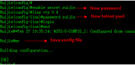
3. set telnet password
ruijie(config)#line vty 0 4
ruijie(config-line)#password ruijie
4. set enable password
Ruijie(config)#enable password ruijie
III. Verification
Telnet 192.168.1.1

Input telnetpassword
Input enablepassword
1.1.3 SSH Management
I. Network Topology
II. ConfigurationSteps
1. enable SSH service
Ruijie#configure terminal
Ruijie(config)#enable service ssh-server
2. generate key
Ruijie(config)#crypto key generate dsa
Choose the size of the key modulus in the range of 360 to2048 for your Signature Keys. Choosing a key modulus greater than 512 may takea few minute
How many bits in the modulus [512]: //press enter
% Generating 512 bit DSA keys ...[ok]
3. configure IP address
Ruijie(config)#interface gigabitEthernet 0/0
Ruijie(config-if-GigabitEthernet 0/0)#ip address 192.168.1.1255.255.255.0
Ruijie(config-if-GigabitEthernet 0/0)#exit
Solution 1:password login
Ruijie(config)#line vty 04
Ruijie(config-line)#login
Ruijie(config-line)#password ruijie
Ruijie(config-line)#exit
Ruijie(config)#enable password ruijie
Ruijie(config)#end
Ruijie#write
Solution 2: username & password login
Ruijie(config)#line vty 0 4
Ruijie(config-line)#login local
Ruijie(config-line)#exit
Ruijie(config)#username admin password ruijie
Ruijie(config)#enable password ruijie
Ruijie(config)#end
Ruijie#write
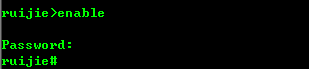
III. Verification
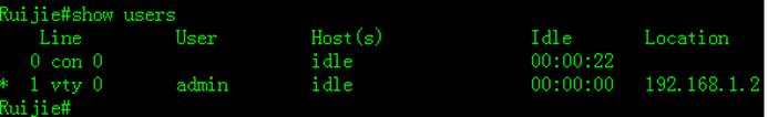
check SSHservice
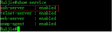
check SSHservices
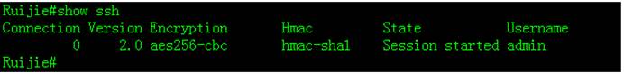
show users
1.1.4 Creating a ManagementIP Address
Creating aManagement IP Address
The SVI and routerport address can be used as the management address of the layer 3 switch.
Layer 3 Switch:
The address of alayer-3 switch can be configured for management or communication, for example,as the gateway for a user.
ConfigurationMethod 1:
Ruijie>enable
Ruijie#configure terminal
Ruijie(config)#interface vlan 10
Ruijie(config-if-VLAN 10)#ip address 192.168.1.1255.255.255.0
Ruijie(config-if-VLAN 10)#end
Ruijie#write
Note: To configure the address for VLANs otherthan VLAN 1 in interface configuration mode, create the corresponding VLANfirst; otherwise, a failure prompt is displayed.
Configuration Method2:
Ruijie>enable
Ruijie#configure terminal
Ruijie(config)#int GigabitEthernet 1/1
Ruijie(config-if-GigabitEthernet 1/1)#no switchport------>configurethe port as layer 3 port before configuring ip address
Ruijie(config-if-GigabitEthernet 1/1)#ip add 192.168.16.1255.255.255.0
Ruijie(config-if-GigabitEthernet 1/1)#end
Ruijie#write------>save configuration after checking.
Verification
Ruijie#show ip int brief
Interface IP-Address(Pri) IP-Address(Sec) Status Protocol
GigabitEthernet 1/1 192.168.16.1/24 noaddress up up
VLAN 10 192.168.1.1/24 noaddress up up
VLAN 100 192.168.100.1/24 192.168.10.1/24 up up
1.1.5 Configuring a DefaultGateway
Configuring theDefault Gateway of a Switch
Configure thedefault gateway, that is, default route, of a layer 3 switch.
Ruijie>enable
Ruijie#configure terminal
Ruijie(config)#ip route 0.0.0.0 0.0.0.0 192.168.1.254------>configuredefault gateway of switch as 192.168.1.254
Ruijie(config)#end
Ruijie#write------>save configuration after checking.
Verification
Ruijie#show ip route
Codes:C - Connected, L - Local, S - Static
R - RIP, O - OSPF, B - BGP, I - IS-IS, V - Overflow route
N1 - OSPF NSSA external type 1, N2 - OSPF NSSA external type2
E1 - OSPF external type 1, E2 - OSPF external type 2
SU - IS-IS summary, L1 - IS-IS level-1, L2 - IS-IS level-2
IA - Inter area, * - candidate default
Gateway of last resort is 192.168.1.254 to network 0.0.0.0
S* 0.0.0.0/0 [1/0] via 192.168.1.254
1.2 Firmware Upgrade
Overview
Two upgradepackages are available to 11.X switches, namely rack package and patch package.
A rack packagecontains main installation packages of the supervisor module and all line cardsand is used to upgrade all line cards on a rack device at one time.
A hot patch packagecontains hot patches for several functional components and is generally used tofix minor bugs. The functional component package can be patched by upgradingthe hot patch package. After the upgrade, the device can immediately have newfeatures without being restarted.
Both the rackpackage and the hot patch package are upgraded with their configurations saved.
Notes(Must-Read)
The difference between an 11.X box-type switch and arack-type switch lies in that the former restarts after the upgrade command isrun while the latter restarts after the reload command is run.
Ruijie#upgrade flash:S2910_RGOS11.4(1)B1_02162700_install.bin
Upgrade the device must be auto-reset after finish, are yousure upgrading now?[Y/N]y
Upgrade in theRunning Mode
Rack PackageUpgrade Using a USB Flash Disk
Notes
1. To fix softwarebugs or get new features, upgrade the switch software version in the runningmode.
2. A USB flash diskis recommended for 11.X switch upgrade because the installation package is bigand upgrade using other methods is slow. Upgrade with a USB flash disk is easyand quick.
3. The CMsupervisor module only has a capacity of 512 MB. Therefore, the rack packagecan be directly upgraded only with a USB flash disk.
4. If the CMsupervisor module has a capacity of 1 GB, upgrade the device by copying theinstallation package from TFTP to the installation partition as well as byusing a USB flash disk. Run the dir install: command to view thecorresponding drive.
5. If the CMIIsupervisor module has a large capacity, upgrade the device by copying theinstallation package from TFTP to the data partition as well as using a USBflash disk. Run the dir flash: command to view the corresponding drive.
Patch PackageUpgrade Using a USB Flash Disk
Notes
1. To fix softwarebugs or get new features, upgrade the switch software version in the runningmode.
2. A hot patchpackage contains hot patches for several functional components and is generallyused to fix minor bugs. The functional component package can be patched byupgrading the hot patch package. After the upgrade, the device can immediatelyhave new features without being started.
3. There is abaseline version for the patch package upgrade. Upgrade the device to thecorresponding baseline version before upgrading the patch package. The devicemay be upgraded compulsively to the corresponding baseline version but it maycause version incompatibility. Therefore, compulsive upgrade is not advised.
4. To permanentlyactivate patches, run the patch active command to temporarily activatethe patch before running the patch running command.
1.2.2 Upgrade with USB Drive
I. Configuration Tips
Run the show version detail commandto display the current version, that is, system software number.
Verify the upgrade file used by checking Release Notes.
Copy the upgrade file from the PC to the root directoryof the USB flash drive.
Insert the USB flash drive to the USB port of thesupervisor engine. The USB flash drive is automatically identified.
Note: Before removing the USB flash drivefrom the switch, run the show usb command to check the USB ID, and then run theusb remove xx command to remove the USB flash drive.

II. ConfigurationSteps
1. On CLI, run the upgradecommand.
Ruijie#dir usb0: Checks whether the upgrade file exists onthe USB flash drive.
Ruijie#upgrade usb0: /xxxxx_install.bin (xxxx_install.bin isthe upgrade file copied to the USB flash drive)
2. Wait until the upgradeprogress reaches 100%, or run the show upgrade status command to check theupgrade progress.
Ruijie#show upgrade status
3. Wait until the upgradeprocess of all the line cards, FE cards, and supervisor engines reaches 100%and the result is success, run the reload command to restart the device. (Theentire upgrade process generally takes four to five minutes and does not affectservices. In this operation, the Flash file on the line card is upgraded, butthe earlier version still runs on the memory.) After the device is restarted,the new version runs.
4. Wait three to fiveminutes until the device is restarted.
III. Verification
Ruijie#show version detail
1.2.3 Upgrade with FTP
Run the showversion detail command to display the current version, that is, system softwarenumber.

Verify the upgradefile used by checking Release Notes.
II. ConfigurationSteps
1. Start the FTP server onthe device, and designate the root directory as the USB0 root directory. (Thespace on the built-in Flash of CMI is small, and may be insufficient forstoring the upgrade file. The CMII can be specified as the Flash root directory.),the reference commands are as follows:
Ruijie(config)#ftp-server username admin
Ruijie(config)#ftp-server password ruijie
Ruijie(config)#ftp-server topdir usb0: / //The USBflash drive must be installed in advance on the main engine.
Ruijie(config)#ftp-server timeout 300
Ruijie(config)#ftp-server enable
2. The local PC serves asthe FTP client. Start the client software (such as FLASHFTP) and connect to theFTP server (N18K). Ensure that the PC can communicate properly with the S86E.
3. Use the FTP client onthe PC to load the upgrade file to the FTP server.
4. Run the upgrade command.(The subsequent procedures and methods are the same as those in the USB upgrademode.)
The only differencebetween the FTP and USB onsite upgrade modes lies in the file transfer mode. InFTP upgrade mode, the upgrade file is transferred to the remote device throughFTP to meet the remote upgrade requirement. In USB onsite upgrade mode, theupgrade file is directly copied from a PC to the USB flash drive.
The subsequentupgrade method is the same. That is, run the upgrade command to update the fileand then restart the device to finish the upgrade.
1.2.4 Upgrade with TFTP
Run the show versiondetail command to display the current version, that is, system software number.
Verify the upgrade fileused by checking Release Notes.
I. ConfigurationSteps
1. Start the TFTPserver on the PC and specify the directory of the upgrade file. Ensure that thePC communicates properly with the S86E.
2. The S86E servesas the TFTP client. The upgrade method is the same as that in the common TFTPupgrade mode. Copy the upgrade file to the USB flash drive on the CMI, or tothe built-in Flash on the CMII.
Ruijie#copy tftp://192.168.1.1/S86e_install.bin usb0://S86e_install.bin
4. Run the upgrade command.(The subsequent procedures and methods are the same as those in the USB upgrademode.)
The only differencebetween the TFTP and USB onsite upgrade modes lies in the file transfer mode.In TFTP upgrade mode, the upgrade file is transferred to the remote devicethrough TFTP to meet the remote upgrade requirement. In USB onsite upgrademode, the upgrade file is directly copied from a PC to the USB flash drive.
The subsequentupgrade method is the same. That is, run the upgrade command to update the fileand then restart the device to finish the upgrade.
The TFTPtransmission rate is lower than the FTP transmission rate. Data is transmittedusing TCP in FTP mode, and using UDP in TFTP mode. TFTP is simple and easy touse.
1.2.5 Install Patch
1. 11.X is amodular OS and the bug of a software function can be fixed by using a patch.After the patch is installed, the device can fix the bug and can run normallywithout being restarted. This OS is applicable to the scenario that imposesrigid requirements on the network interruption time during maintenance.
2. A patch is inthe uninstalled, installed, or activated state, where:
The installed stateindicates that the patch is installed on the memory of the device but the pathfunction does not take effect yet.
Only a patch in theactivated state takes effect.
I. ConfigurationSteps
1. Install a patch.
Copy the path fileto a USB flash drive, and run the upgrade command to install the path.Thereference command is as follows:
Ruijie#upgrade usb0: /N18K-octeon-cm_RGOS11.0(1b2)_20140708_patch.bin
2. Activate apatch.
The referencecommand is as follows:
Ruijie#patch active slot all
Ruijie#patch running slot all
Note: active meansthat the patch is currently effective and is ineffective after the device isrestarted. running indicates that the patch is effective permanently.
3. Display the patchstatus.
The referencecommand is as follows:
Ruijie#show patch slot all
1.3 Restore Password
I. Configuration Tips
1.Prepare console cable before recovering
2.Password recovery require system rebooting and network downtime
3.Improper operation may cause config file lost.
II. ConfigurationSteps
1. connect console cable tothe switch
2. Refer to chapter systemmanagement>console management
1) manually reboot the switch
2) Press Ctrl+C when systemrebooting
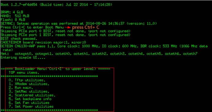
3) Press CTRL +Q to enter uboot CLI mode
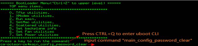
4) then system will rebootautomatically
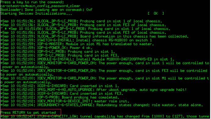
5) At this moment, nopassword is required to enter CLI
![]()
Note: The passwordis reset just temporarily .Once you quit privilege mode, password is requiredagain. You have to reset the password quickly.
6) Reset new password
7) Verify new password
Login with the newpassword
Configuration Guide
2.1 Initialization
2.1.1 Overview (Must Read)
For Standardizationreason, we strongly suggest you to initialize every new switch following thesteps below:
1. Hostname(mandatory)
2. Access a device(mandatory , see Chapter Installation and DeviceManagement --->System Management)
2.1. Assignmanagement IP address(mandatory)
2.2. Set defaultgateway(optional for layer 3 switch,but mandatory for layer 2 switch)
2.3. Telnet(optional)
2.4. SSH(recommended)
2.5. Web Userinterface(optional)
3. Log(mandatory , and choose one)
3.1. Record log toFLASH(recommended)
3.2. Send log toserver(recommended)
4. Clock(mandatory , and choose one)
4.1. Local clock(recommended)
4.2. NTP(recommended)
5. Configuring aport(mandatory)
5.1. Portdescription(mandatory)
5.2. Speed, duplexand flowcontrol (optional)
5.3. Combo port(optional)
5.4. ACCESS orTRUNK port (mandatory)
5.5. Storm control(recommended)
6. SNMP(recommended)
6.1. SNMPV1/V2(recommended)
6.2. SNMPV3(recommended)
7. SPAN(optional)
7.1. Many to onemirror(Optional)
7.2. One to manymirror(Optional)
7.3. Flow-basedmirror(Optional)
2.1.2 Hostname
Configuring Hostname
By default, system name is "Ruijie mostly, theexample shows how to configure the system name:
Ruijie>en
Ruijie#configure terminal
Ruijie(config)#hostname Switch ------>changename to "Switch"
Switch(config)#end
Switch#write ------>saveconfiguration
Note:We suggest you to name a switch with these information physicallocation(AA), network location(BB) ,model(CC),serial number(DD), and the formatis (AA_BB_CC_DD) , for example:
Ruijie(config)#hostname WLZX_Core_S8610_1
WLZX_Core_S8610_1(config)#
Verifying
Switch#show run
Building configuration...
Current configuration : 34129 bytes
version NOS_11.0_4_21
hostname hostname Switch
2.2 Log
2.2.1 Copying log to FLASH
I. Requirements
1. Copy logs with a severity higher thandebugging in the flash ,then set size of each log file to 128Kbytes.
2. Set size of log buffer to 128Kbytes.
3. Record action when user logs in andoperates.
4. Add system name , sequence number andtime stamps to each log entry.
II. Network Topology
III. Configuration Tips
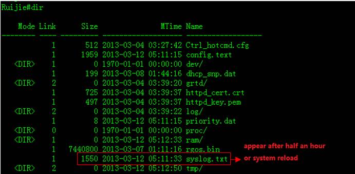
System doesn't copy logs from buffer to flashonce finishing configuration, andit costs about half an hour to copy logs from buffer to flash , or the log bufferexceeds.
IV. ConfigurationSteps
Ruijie>enable
Ruijie#configure terminal
Ruijie(config)#logging file flash:syslog 6 ------>setlog file name to "syslog" and system copies all logs with severityfrom 0 to 6 to flash
Ruijie(config)#logging file flash:syslog 131072 ------>setsize of each log file in flash to 128K
Ruijie(config)#logging buffered 131072 ------>setlog buffer size to 128K
Ruijie(config)#logging userinfo ------>recordactions when user logs in
Ruijie(config)#logging userinfo command-log ------>recordactions when user operates commands
Ruijie(config)#service sysname ------>addsystem name to each log entry
Ruijie(config)#service sequence-numbers ------>addsequence number to each log entry
Ruijie(config)#service timestamps ------>addtime stamps to each log entry
Ruijie#wr
Note:We suggest you to set log buffer sizeto 128K because the buffer size is too small by defaut.
If the 1st log file is full , system copieslogs to 2nd log file , then the 3th log file ……there're 16 log files at most inthe same time , and if all 16 log files are full ,the new log entry overwritesthe old one , so Log file never takes up the whole flash room.
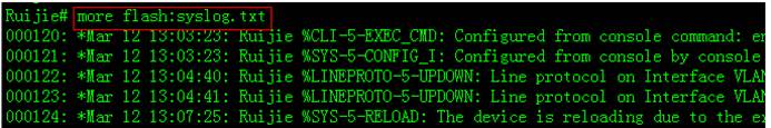
Enter "more flash:xxx" privilegeEXEC command to display log entries and "delete flash:xxx" privilegeEXEC command to delete log file in flash.
v. Verification
1. This example shows how to display logs inbuffer
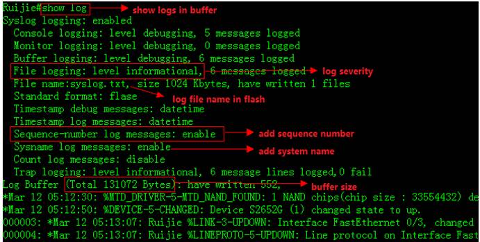
2. Enter "dir" privilege EXECcommand to check log files in flash
3. This example shows how to display logs inflash
4. Enter "clear logging" privilegeEXEC command to clear logs in buffer
![]()
2.2.2 Copying log to Server
I. Requirements
Copy logs with severity from 0 to 7 tosyslog server.
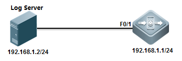
II. Network Topology
III. Configuration Tips
Timestamps and sequence number features must be enabledbefore system copys logs to log server
IV. ConfigurationSteps
Ruijie>enable
Ruijie#configure terminal
Ruijie(config)#service sequence-numbers ------>enablesequence number
Ruijie(config)#service timestamps ------>enabletimestamps
Ruijie(config)#interface vlan 1
Ruijie(config-if-VLAN 1)#ip address 192.168.1.1 255.255.255.0
Ruijie(config-if-VLAN 1)#exit
Ruijie(config)#logging server 192.168.1.2 ------>specifylog server IP address
Ruijie(config)#logging source ip 192.168.1.1 ------>specifyIP address on switch to communicate with log server
Ruijie(config)#logging trap 7 ------>copyall logs(severity from 0 to 7) to log server
Ruijie(config)#end
Ruijie#wr
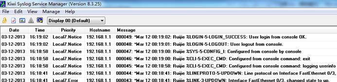
V. Verification
This example shows how to verify the logs ina syslog server using "Kiwisyslog"
2.2.3 Log Filtering
Scenario
By default, the log information generated onthe system can be output to various destinations. You can use the log filteringfunction to display required log information.
Features
1 The administrator can choose to hide some typesof log information as required.
2 Generally, log information of all modules isdisplayed on the console or terminal. You can set log filter rules to enablelog information printing on designated terminals or print only certain types oflog information on designated terminals.
3 Two types of log information filtering aresupported, including "contain only..." and "filteronly...". Only one type of filtering is supported.
Working Principles & ConfigurationDetails
Log filtering configuration mainly covers thefilter rules, filter direction, and filter mode. During the configurationprocess:
1 If only the filter direction and filter mode areconfigured, the configuration does not take effect and log information is notfiltered.
2 If only the filter rule is configured, theconfiguration takes effect. Log information in all directions is filtered andthe filter mode is filter only.
1) Filter rule: sets the rule for filteringlog information in global mode. Exact match and singular match are supported.
Filter rule in exact match mode: loggingfilter rule exact-match [ module module-name mnemonic mnemonic-name level level]
Filter rule in singular match mode: loggingfilter rule single-match [ level level | mnemonic mnemonic-name | modulemodule-name ]
Parameter description
exact-match Indicatesan exact-match filter based on all three filter options. In exact match mode,all three filter options, including log module name (module module-name), loglevel (level level), and mnemonic character (mnemonic mnemonic-name), must beselected.
single-match Indicatesa single-match filter based on all three filter options. In exact match mode,all three filter options, including log module name (module module-name), loglevel (level level), and mnemonic character (mnemonic mnemonic-name), must beselected.
module module-name Indicatesthe name of the module about which the log information is to be filtered.
mnemonic mnemonic-name Indicates the name of the mnemonic character for which thelog information is to be filtered.
level level Indicatesthe log level to be filtered.
Tips
1. In some scenarios, you may want to filter out certain types of loginformation. You can use the exact match mode and specify the module name,mnemonic character name, and log level in configuring the filter rule.
2. In some scenarios, you may want to filter out some types of loginformation. You can use the single match mode and specify the module name,mnemonic character name, or log level in configuring the filter rule.
3. If the configuration of the module name, mnemonic character name, orlog level in a single-match filter rule is the same as that in an exact-matchfilter rule, the single-match filter rule is assigned with higher priority thanthe exact-match filter rule.
Configuration example
1. Set the filter rule to exact match, modulename to LOGIN, log level to 5, and mnemonic character to LOGOUT.
Ruijie(config)# logging filter ruleexact-match module LOGIN mnemonic LOGOUT level 5
2. Set the filter rule to single-matchand module name to SYS.
Ruijie(config)# logging filter rulesingle-match module SYS
FAQs
1. To filter logs 046188: *Aug 13 08:36:16: 401-C1&D1-RG-N18010%SPANTREE-6-RCVDTCBPDU: (*2/M1) Received tc bpdu on port AggregatePort 256 onMST0
Command: ruijie(conifg)#logging filter ruleexact-match module SPANTREE mnemonic RCVDTCBPDU level 6
2. To filter logs *Jul 30 12:35:51: %SNMP-3-AUTHFAIL:Authentication failure for SNMP req from host 185.94.111.1
Command: ruijie(conifg)#logging filter ruleexact-match module SNMP mnemonic AUTHFAIL level 3
3. To filter logs %PARAM-6-CONFIG_SYNC: Sync'ingthe startup configuration to the standby supervisor
Command: ruijie(config)#logging filter ruleexact-match module PARAM mnemonic CONFIG_SYNC level 6
2) Filter direction: sets the direction forfiltering log information in global mode.
logging filter direction { all | buffer |file | server | terminal } //By default, the filter direction is set to all,that is, to filter log information in all directions.
default logging filterdirection // The filter direction for the log informationrestoration command is all.
Parameter description
all Indicates to filter loginformation in all directions, including the console, virtual type terminal(VTY), log buffer area, log file, and log server.
buffer Indicates to filterlogs sent to the log buffer area, that is the logs configured in the showlogging command.
file Indicates to filter the logssent to the log files.
server Indicates to filter thelogs sent to the log server.
terminal Indicates to filterlogs sent to the console and VTY (including via Telnet and SSH).
Tips
1.Generally, you may filter the logs meetingthe filter rule in all directions (including to the console, VTY terminal, logbuffer area, log file, and log server) after the log filter function isconfigured. In some cases, you may want to filter logs only for certaindestinations. For example, you may need the logs filtered out for the terminalon the log file or log server. In these cases, you need to set log filter rulesfor the terminal direction.
2. You can set the filter direction tomultiple destinations by separating each other with a vertical line"|" or only one destination.
3) Filter type: sets the log informationfilter type. The configuration takes effect globally.
logging filter type { contains-only |filter-only } //The default value is filter-only, indicating that onlyfilter is used.
Parameter description
contains-only Indicates thatonly logs containing keywords specified in the filter rule are output.
filter-only Indicates that logscontaining keywords specified in the filter rule are filtered out and notoutput.
Tips
1. In some scenarios, a module may output toomuch log information that it may causes screen downpour on the terminal withfew valuable information being displayed. In this case, you can use thefilter-only mode to filter out undesired log information.
2. In some scenarios, you may want to checkwhether a certain type of log information is generated only. In this case, youcan use the contain-only mode to output logs matching the filter rule to theterminal for observation.
3. In actual application, the two filtermodes are mutually exclusive. Choose one filter mode only.
Configuration example
[Example 1]
[Requirement]
Assume there are following log informationfiltering requirements on the live network:
1. Set the filter direction to terminaland server.
2. Set the filter mode to filter-only.
3. Set the filter rule to single-matchand module name to SYS.
2. Set the filter mode to filter-only.
3. Set the filter rule to single-matchand module name to SYS.
3. Set the filter rule to single-matchand module name to SYS.
[Configuration method]
Configure log information filter on the system.
Ruijie# configure terminal
Ruijie(config)# logging filter direction server
Ruijie(config)# logging filter direction terminal
Ruijie(config)# logging filter type filter-only
Ruijie(config)# logging filter rule single-match module SYS
[Verification method]
1. Run the show running-config | includelogging command to check the parameter configuration.
2. Check the output log information on thesystem by entering and quitting the global configuration mode
Ruijie#configure
Enter configuration commands, one per line. End with CNTL/Z.
Ruijie(config)#exit
.
2.3 Clock
2.3.1 Local Clock
I. Requirements
System time plays a very important role fortroubleshooting and logs .We suggest you to deploy local clock to a scenario inwhich there're only a few nodes with a small maintenance.
II. ConfigurationSteps
Ruijie>enable
Ruijie#configure terminal ------>enterglobal configuration mode
Ruijie(config)#clock timezone beijing 8 ------>settimezone to UTC +8
Ruijie(config)#exit
Ruijie#clock set 18:00:00 12 3 2013 ------>setclock in format "hh:mm:ss month day year"
Ruijie(config)#end
Ruijie#write ------>doubleconfirm and save configuration
III. Verification
Ruijie#show clock
18:01:03 beijing Tue, Dec 3, 2013
2.3.2 NTP
Overview
Network Time Protocol (NTP) is designed for timesynchronization on network devices. A device can synchronize its clock sourceand the server. Moreover, the NTP protocol can provide precise time correction(less than one millisecond on the LAN and dozens of milliseconds on the WAN,compared with the standard time) and prevent from attacks by means ofencryption and confirmation.
To provide precise time, NTP needs precise time source,the Coordinated Universal Time (UTC). The NTP may obtain UTC from the atomclock, observatory, satellite or Internet. Thus, accurate and reliable timesource is available.
To prevent the time server from malicious destroying,an authentication mechanism is used by the NTP to check whether the request oftime correction really comes from the declared server, and check the path ofreturning data. This mechanism provides protection of anti-interference.
Ruijie switches support the NTP client and server. Thatis, the switch can not only synchronize the time of server, but also be thetime server to synchronize the time of other switches. But when the switchworks as the time server, it only support the unicast server mode.
I. Requirements
Switch synchronizes system clock to NTPServer in order to keep system clock more accurate.
II. Network Topology
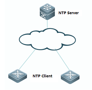
III. Configuration Tips
1. Basic network routes setting
2. (Optional)Configuring a switch as NTPServer
3. Configuring a switch as NTP client
4. (Optional)Specifying a interface onswitch to communicate with NTP Server
IV. ConfigurationSteps
NTP configuration without authentication
1. Basic network routes setting
Ensure that NTP client can communicate withthe NTP server
2. (Optional) Configuring a switch as NTPServer
Note:
Mostly NTP server is a particular serverrather than a switch in production network. This example shows how to configurea switch as a NTP server:
Ruijie(config)#ntp master
3. Configuring a switch as NTP client
Ruijie(config)#ntp server 192.168.2.1 ------>setNTP server IP address
Ruijie(config)#ntp update-calendar ------>allowsystem to save clock in hardware even power interruption
4. (Optional) Specifying a interface onswitch to communicate with NTP Server
Ruijie(config)#ntp server 192.168.1.2 source loopback 0 ------>specify interface loopback 0 to communicate with NTP Server
NTP configuration with authentication
1. Basic network routes setting
Ensure that NTP client can communicate withthe NTP server
2. (Optional) Configuring a switch as NTPServer
Note:
Mostly NTP server is a particular serverrather than a switch in production network. This example shows how to configurea switch as a NTP server and how to configure NTP authentication on a switchNTP Server
Ruijie(config)#ntp master
Ruijie(config)#ntp authenticate ------>enable NTPauthentication
Ruijie(config)#ntp authentication-key 6 md5 ruijie ------>NTPkey id is "6" , and password is "ruijie"
Ruijie(config)#ntp trusted-key 6
3. Configuring a switch as NTP client
Ruijie(config)#ntp update-calendar ------>allowsystem to save clock in hardware even power interruption
Ruijie(config)#ntp authenticate ------>enableNTP authentication
Ruijie(config)#ntp authentication-key 6 md5 ruijie ------>NTPkey id is "6" , and password is "ruijie"
Ruijie(config)#ntp trusted-key 6
Ruijie(config)#ntp server 192.168.2.1 key 6 ------>applykey id 6 to corresponding NTP server 192.168.2.1
4. (Optional) Specifying a interface onswitch to communicate with NTP Server
Ruijie(config)#ntp server 192.168.1.2 source loopback 0 ------>specifyinterface loopback 0 to communicate with NTP Server
V. Verification
1. This example displays the clock on NTPserver
![]()
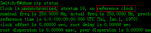
2. This example displays the clock on NTPclient before synchronization
![]()
3. This example displays NTP status on NTPclient before synchronization
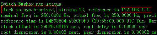
4. System returns a message aftersynchronizing successfully:
*Mar 12 10:55:04: %SYS-6-CLOCKUPDATE: Systemclock has been updated to 10:55:04 UTC Tue Mar 12 2013.
This example displays NTP status on NTPclient before synchronization
2.4 Configuring a Layer 2 Port
2.4.1 Port Description
Function Overview
Port description is very important for dailymaintenance and trouble shooting. We suggest you to use the format "Link-peername-peer port" to define port description. For example:
Ruijie(config-if-GigabitEthernet 0/1)#description Link-to-WLZX_Core_S8610_1-G1/2
I. ConfigurationSteps
Configuring port description on G0/1
Ruijie#configure terminal
Ruijie(config)#interface gigabitEthernet 0/1
Ruijie(config-if-GigabitEthernet 0/1)#descriptionLink-to-Core-S8610_1-G2/3
Ruijie(config-if-GigabitEthernet 0/1)#end
Ruijie#write
II. Verification
Ruijie#show interfaces description
Interface Status Administrative Description
------------------------ -------- -------------- -----------
GigabitEthernet 0/1 down up Link-to-Core-S8610_1-G2/3
GigabitEthernet 0/2 down up
GigabitEthernet 0/3 down up
2.4.2 Speed, Duplex and Flowcontrol
Overview
By default, speed and duplex negotiateautomatically. You can also set speed and duplex manually to ensure that bothends of a link have the same speed and duplex .Usually we keep the defaultsetting for flow control.
I. ConfigurationSteps
In the following example, the"speed" config-interface command with the keyword 100 is used tomanually set speed on Giga0/24 to 100M
Ruijie>enable
Ruijie#configure terminal
Ruijie(config)#int gigabitEthernet 0/24
Ruijie(config-if-GigabitEthernet 0/24)#speed 100
Ruijie(config-if-GigabitEthernet 0/24)#end
Ruijie#write
In the following example, the"duplex" command config-interface with the keyword full is used tomanually set duplex on Giga0/24 to full duplex
Ruijie>enable
Ruijie#configure terminal
Ruijie(config)#int gigabitEthernet 0/24
Ruijie(config-if-GigabitEthernet 0/24)#duplex full
Ruijie(config-if-GigabitEthernet 0/24)#end
Ruijie#write
This example shows how to disable flowcontrol feature on Giga0/1
Ruijie#configure terminal
Ruijie(config)#interface gigabitEthernet 0/1
Ruijie(config-if-GigabitEthernet 0/1)#flowcontrol off
Ruijie(config-if-GigabitEthernet 0/1)#end
Ruijie#write
Note:Bydefault flow control feature is enabled, but different switches vary,and you can enter "show interface" privilege EXEC command toverify.
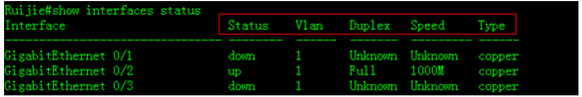
II. Verification
This example shows how to display interfacestatus including duplex and speed.
2.4.3 Combo Port
I. ConfigurationSteps
Following example shows how to convert combo mode onGiga0/23 to fiber
Ruijie>enable
Ruijie#configure terminal
Ruijie(config)#interface gigabitEthernet 0/23
Ruijie(config-if-GigabitEthernet 0/23)#medium-type fiber ------>convertcombo mode to fiber
Ruijie(config-if-GigabitEthernet 0/23)#end
Ruijie#write ------>confirm and save
Following example shows how to convert combo mode onGiga0/23 to copper
Ruijie>enable
Ruijie#configure terminal
Ruijie(config)#interface gigabitEthernet 0/23
Ruijie(config-if-GigabitEthernet 0/23)#medium-type copper ------>convertcombo mode to copper
Ruijie(config-if-GigabitEthernet 0/23)#end
Ruijie#write
II. Verification
1. To display combo mode status , enter"show interface status" privilege EXEC command
Ruijie#show interfaces status
Interface Status Vlan Duplex Speed Type
-------------------------------- -------- ------ ------- --------- ------
GigabitEthernet 0/22 down 1 Unknown Unknown copper
GigabitEthernet 0/23 up 1 Full 1000M fiber
GigabitEthernet 0/24 down 1 Unknown Unknown copper
2. This example shows how to display thetransceiver information of Giga0/23
Ruijie#show interfaces g0/23 transceiver
Transceiver Type : 1000BASE-LX-SFP
Connector Type : LC
Wavelength(nm) : 1310
Transfer Distance :
SMF fiber
-- 10km
50/125 um OM2 fiber
-- 550m
62.5/125 um OM1 fiber
-- 550m
Digital Diagnostic Monitoring : NO ------>Thistransceiver doesn't support DDM . DDM provides you the light intensity ofreceiving and sending direction.
Vendor Serial Number : LP201093226676
3. This example shows how to display thelight intensity of a 10G transceiver which supports DDM
Ruijie#show interfaces tenGigabitEthernet 1/25 transceiverdiagnosis
Current diagnostic parameters[AP:Average Power]:
Temp(Celsius) Voltage(V) Bias(mA) RXpower(dBm) TX power(dBm)
26(OK) 3.26(OK) 5.22(OK) -3.65(OK)[AP] -2.09(OK)
4. This example shows how to display thetransceiver alarm
Ruijie#show interfaces tenGigabitEthernet 1/25 transceiveralarm ------> if the transceivers is plugged in , but the portdoesn't come up , system returns the following warning message
RX power low
RX loss of signal
Module not ready
RX not ready
RX CDR loss of lock
Ruijie#show interfaces tenGigabitEthernet 1/25 transceiveralarm ------>if the transceivers is plugged in and the port comesup , system returens no warning message
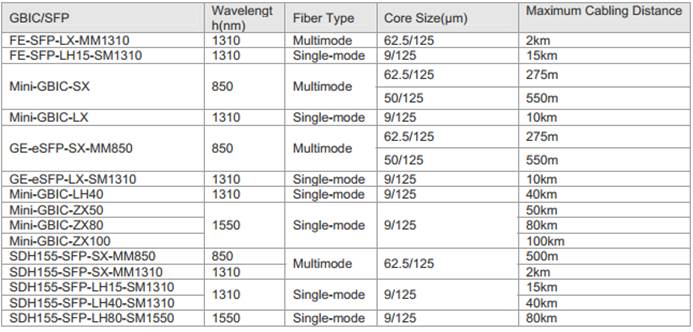
Ruijie transceivers specification
1. MINI-GBIC transceiver:
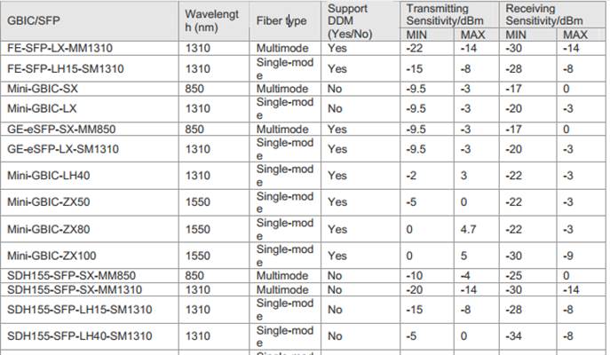
MINI-GBIC cabling specification:
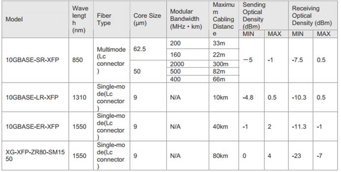
2. 10G XFP
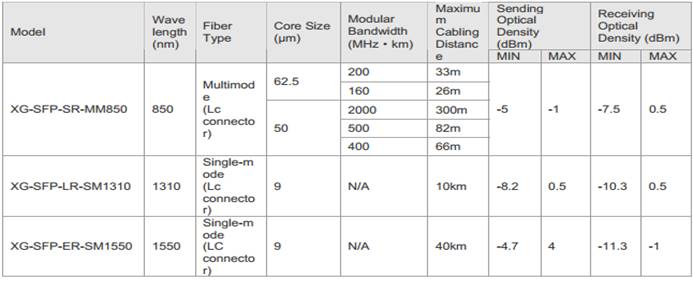
3. 10G SFP+
2.4.4 Access orTrunk Port
Note:Bydefault , trunk port carries traffic for all vlans that is created , and westrongly recommend you to prune every trunk port to allow only the traffic ofuseful vlan pass through in case that unknown unicast ,broadcast and multicastpackets floods through the overall network ,leading to a heavier CPU burden anduseless consumption of system resource.
I. ConfigurationSteps
1. Configuring access port
The following example shows how to configureinterface F0/1 as an access port and assign interface F0/1 to VLAN 100
Ruijie>en
Ruijie#conf t
Ruijie(config)#interface fastEthernet 0/1
Ruijie(config-if)#switchport mode access
Ruijie(config-if)#switchport access vlan 100
Ruijie(config-if)#end
Ruijie#wr
Note:Bydefault, all ports are access mode and belongs to VLAN 1
Enter "show vlan" privilege EXECcommand to verify that interface F0/1 belongs to VLAN 100
Ruijie# show vlan
VLAN Name Status Ports
---- -------------------------------- --------- -----------------------------------
1 VLAN0001 STATIC Fa0/3, Fa0/4,Fa0/5
Fa0/6, Fa0/7,Fa0/8, Fa0/9
Fa0/10,Fa0/11, Fa0/12, Fa0/13
Fa0/14,Fa0/15, Fa0/16, Fa0/17
Fa0/18,Fa0/19, Fa0/20, Fa0/21
Fa0/22,Fa0/23, Fa0/24, Fa0/25
Fa0/26,Fa0/27, Fa0/28, Fa0/29
Fa0/30,Fa0/31, Fa0/32, Fa0/33
Fa0/34,Fa0/35, Fa0/36, Fa0/37
Fa0/38,Fa0/39, Fa0/40, Fa0/41
Fa0/42,Fa0/43, Fa0/44, Fa0/45
Fa0/46,Fa0/47, Fa0/48, Gi0/49
Gi0/50
100 VLAN0100 STATIC Fa0/1,Fa0/2
2. Configuring trunk port
The following example shows how to configure interfaceG0/49 as a trunk port
Ruijie#configure terminal
Ruijie(config)#interface gigabitEthernet 0/49
Ruijie(config-if)#switchport mode trunk
Ruijie(config-if)#end
In the following example, "show interfacetrunk" privilege EXEC command is used to verify all trunk port status
Ruijie# show interfaces trunk
Interface Mode Native VLAN VLAN lists
------------------------ ------ ----------- ----------
FastEthernet 0/48 Off 1 ALL
GigabitEthernet 0/49 On 1 ALL
GigabitEthernet 0/50 Off 1 ALL
3. Pruning a Trunk port (Mandatory)
This example shows how to prune a trunk port to carrytraffic only for vlan 5, 10 and 20-30
Ruijie#configure terminal
Ruijie(config)#interface gigabitEthernet 0/1
Ruijie(config-if-GigabitEthernet 0/1)#switchport mode trunk
Ruijie(config-if-GigabitEthernet 0/1)#switchport trunkallowed vlan remove 1-4,6-9,11-19,31-4094
Ruijie(config-if-GigabitEthernet 0/1)#end
Ruijie#wr
2.4.5 Storm Control
Overview
1. We suggest you to apply storm-control on edge porton access switch and Don't apply storm-control on uplink port.
2. If access switch doesn't support storm-control , wesuggest you to apply storm-control on distribution switch.
3. The limitation of 100 pps to 300 pps for unknownunicast/broadcast/multicast packets is proper.
I. ConfigurationSteps
To configure storm control on a port with keywordlevel, perform this task:
Ruijie>enable
Ruijie#configure termina
Ruijie(config)#interface gigabitEthernet 0/1
Ruijie(config-if-GigabitEthernet 0/1)#storm-control broadcastlevel 1 ------>storm-control limits the number of broadcast packetsto 1% of the bandwidth that is 1G*1%=10M
Ruijie(config-if-GigabitEthernet 0/1)#storm-control unicast level1 ------>storm-control limites the number of unknown unicastpackets to 1% of the bandwidth that is 1G*1% =10M
Ruijie(config-if-GigabitEthernet 0/1)#storm-control multicastlevel 1
To configure storm control on a port with keyword pps, performthis task:
Ruijie>enable
Ruijie#configure termina
Ruijie(config)#interface gigabitEthernet 0/1
Ruijie(config-if-GigabitEthernet 0/1)#storm-control broadcastpps 200 ------>storm-control limits the number of broadcast packetsto 200 packets per seconds
Ruijie(config-if-GigabitEthernet 0/1)#storm-control unicastpps 200 ------>storm-control limits the number of unknown unicastpackets to 200 packets per seconds
Ruijie(config-if-GigabitEthernet 0/1)#storm-control multicast200
Ruijie(config-if-GigabitEthernet 0/1)#end
II. Verification
Ruijie#show storm-control
Interface Broadcast Control Multicast ControlUnicast Control Action
------------------------- ----------------- -------------------------------- --------
GigabitEthernet 0/1 1 % 1 % 1 % none
GigabitEthernet 0/2 Disabled Disabled Disabled none
GigabitEthernet 0/3 Disabled Disabled Disabled none
2.5 SNMP
2.5.1 SNMPV1/V2
Overview
SNMP:As theabbreviation of Simple Network Management Protocol, SNMP has been a networkmanagement standard (RFC1157) since the August, 1988. So far, the SNMP becomesthe actual network management standard for the support from many manufacturers.It is applicable to the situation of interconnecting multiple systems fromdifferent manufacturers. Administrators can use the SNMP protocol to queryinformation, configure network, locate failure and plan capacity for the nodeson the network. Network supervision and administration are the basic functionof the SNMP protocol.
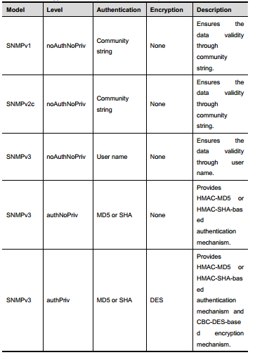
SNMP versions:
SNMPv1 :The first formal versionof the Simple Network Management Protocol, which is defined in RFC1157
SNMPv2C: Community-basedAdministrative Framework for SNMPv2, an experimental Internet protocol definedin RFC1901.
SNMPv3: Offers the followingsecurity features by authenticating and encrypting packets:
1. Ensure that the data are not tampered duringtransmission;
2. Ensure that the data come from a valid data source;
3. Encrypt packets to ensure the data confidentiality;
Both the SNMPv1 and SNMPv2C use acommunity-based security framework. They restrict administrator’s operations onthe MIB by defining the host IP addresses and community string. With the GetBulk retrieval mechanism, SNMPv2C sends more detailed error information type tothe management station. Get Bulk allows you to obtain all the information or agreat volume of data from the table at a time, and thus reducing the times ofrequest and response. Moreover, SNMPv2C improves the capability of handingerrors, including expanding error codes to distinguish different kinds oferrors, which are represented by one error code in SNMPv1. Now, error types canbe distinguished by error codes. Since there may be the management workstationssupporting SNMPv1 and SNMPv2C in a network, the SNMP agent must be able torecognize both SNMPv1 and SNMPv2C messages, and return the correspondingversion of messages.
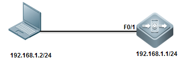
I. Requirements
1. Only SNMP network manager(IP:192.168.1.2/24) can access switch SNMP service with community string"ruijie"
2. SNMP agent on switch sends SNMP trap toSNMP manager actively
3. SNMP manager can get basic information ofswitch ---location, contact method and chassis id
II. Network Topology
III. Configuration Tips
1. Set Read-Only community string andRead-Write community string on switch independently
2. Define ACL to allow authorized SNMPmanager to access SNMP agent of switch only
3. Enable SNMP trap
4. Configure SNMP manager
IV. ConfigurationSteps
1. Define an access-list named "abc"and an entry to permit IP address of SNMP manager
Ruijie(config)#ip access-list standard abc
Ruijie(config-std-nacl)#permit host 192.168.1.2
Ruijie(config-std-nacl)#exit
2. Set read-write community string to"ruijie" and read-only community string to "public" , thenassociate both community strings with ACL to allow only the SNMP manager toaccess SNMP agent of switchonly
Ruijie(config)#snmp-server community ruijie rw abc
Ruijie(config)#snmp-server community public ro abc
3. SNMP agent on switch actively sends trap to SNMP network manager
Ruijie(config)#snmp-server host 192.168.1.2 traps ruijie ------>bydefault , SNMP trap version is version 1
Ruijie(config)#snmp-server host 1.1.1.1 version 2c ruijie ------>setSNMP trap version to version 2c
4. Enable trap feature
Ruijie(config)#snmp-server enable traps
5. Set SNMP optional parameters
Set location
Ruijie(config)#snmp-server location fuzhou
Set contact method
Ruijie(config)#snmp-server contact ruijie.com.cn
Set chassis-id
Ruijie(config)#snmp-server chassis-id 1234567890
6. Assign a management IP address to SVI 1
Ruijie(config)#interface vlan 1
Ruijie(config-if-VLAN 1)#ip address 192.168.1.1 255.255.255.0
7. Save configuration
Ruijie(config-if-VLAN 1)#end
Ruijie#wr
V. Verification
1. This example shows how to verify SNMPagent status
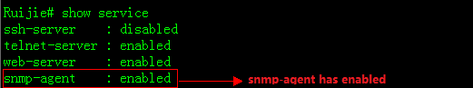
Following example provides how to disableSNMP agent if snmp agent issue leads to heavy load of CPU :
Ruijie(config)#no enable service snmp-agent
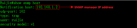
2. This examples shows how to display SNMPhost information
3. This example shows how to access the SNMPagent in a SNMP manager using "Mib-Browser"
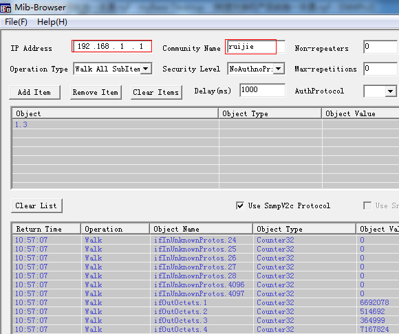
4. Other SNMP manager except for 192.168.1.2cannot access SNMP agent at the same time.
2.5.2 SNMPV3
I. Requirements
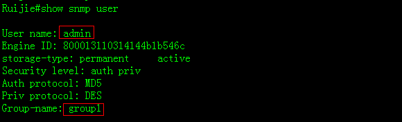
1) The SNMP manager can access the SNMP agent on switch byapplying user-based security model. The user name is "admin",authentication mode is MD5, authentication key is "ruijie",encryption algorithm is DES56, and the encryption key is "123"
2) User "admin" can read the MIB objects underSystem (1.3.6.1.2.1.1) node, and can only write MIB objects under SysContact(1.3.6.1.2.1.1.4.0) node.
3) The switch can actively send authentication andencryption messages to the SNMP manager
II. Network Topology
III. Configuration Tips
1. Create MIB view and specify the includedor excluded MIB objects.
2. Create SNMP group and set the version to"v3"; specify the security level of this group, and configure theread-write permission of the view corresponding to this group.
3. Create user name and associate thecorresponding SNMP group name in order to further configure the user'spermission to access MIB objects; meanwhile, configure the version number to"v3" and the corresponding authentication mode, authentication key,encryption algorithm and encryption key.
4. Configure the address of SNMP manager,configure the version "3" and configure the security level to beadopted.
IV. Configuration Steps
Configuring switch:
Ruijie#configure terminal
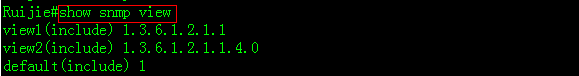
Ruijie(config)#snmp-server view view1 1.3.6.1.2.1.1include ------> Create a MIB view of"view1" and include the MIB object of 1.3.6.1.2.1.1
Ruijie(config)#snmp-server view view2 1.3.6.1.2.1.1.4.0include ------> Create a MIB view of "view2" and includethe MIB object of 1.3.6.1.2.1.1.4.0
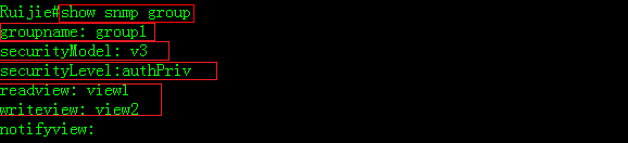
Ruijie(config)#snmp-server group group1 v3 priv read view1write view2 ------>Create a group named "g1" ,using SNMPv3 ;configure security level to "priv" ,and can read "view1" and write "view2"
Ruijie(config)#snmp-server user admin group1 v3 auth md5ruijie priv des56 ruijie123 ------>Create a user named"admin", which belongs to group "group1"; using SNMPv3 andauthentication mode is "md5", authentication key is"ruijie", encryption mode is "DES56" and encryption key is"123".
Ruijie(config)#snmp-server host 192.168.1.2 traps version 3priv admin ------>Configure the SNMP server address as 192.168.1.2 ,using SNMPv3,then configure security level to "priv" and associatethe corresponding user name of "admin"
Ruijie(config)#snmp-server enabletraps ------>Enablethe Agent to actively send traps to NMS
Ruijie(config)#interface vlan 1
Ruijie(config-if-VLAN 1)#ip address 192.168.1.1 255.255.255.0
Ruijie(config-if-VLAN 1)#end
Set SNMP optional parameters
Ruijie(config)#snmp-server location fuzhou
Ruijie(config)#snmp-server contact ruijie.com.cn
Ruijie(config)#snmp-server chassis-id 1234567890
Note: Ifyou don't create a new SNMP view, Ruijie switch uses the default SNMP viewnamed "default" ,including MIB object of 1
Minimun SNMPv3 configuration example:
snmp-server group group1 v3 priv read default writedefault
snmp-server user admin group1 v3 auth md5 ruijie priv des56ruijie123
snmp-server host 192.168.1.2 traps version 3 priv admin
snmp-server enable traps
V. Verification
1. This example shows how to verify SNMPagent status
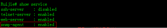
Following example provides how to disableSNMP agent if snmp agent issue leads to heavy load of CPU :
Ruijie(config)#no enable service snmp-agent
2. Following examples show how to displaysnmp view, snmp group and snmp user individually
2.6 SPAN
2.6.1 Many to one mirror
Overview
With SPAN, you can analyze thecommunications between ports by copying a frame from one port to another portconnected with a network analysis device or RMON analyzer. The SPAN mirrors allthe packets sent/received at a port to a physical port for analysis.SPAN doesnot affect the exchange of packets between the source and destination ports.Instead, it copies the frames incoming/outgoing the source port to thedestination port. However, the frames may be discarded on an overfloweddestination port, for example, when a 100Mbps port monitors an 1000Mbps port.
I. Requirements
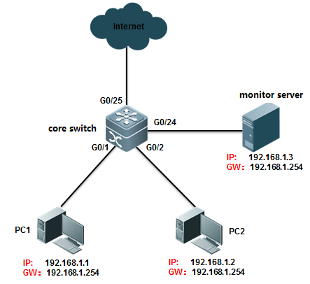
Core switch copies traffic of G0/1 and G0/2on both directions to Monitor Server and Monitor Server can also visit Internetat the same time
II. Network Topology
III. Configuration Tips
Enter "monitor session" globalconfiguration command with "switch" keyword to allow mirrordestination port to forward additional traffic more than mirroring traffic
IV. ConfigurationSteps
Ruijie>enable
Ruijie#configure terminal
Ruijie(config)#monitor session 1 source interfacegigabitEthernet 0/1 both ------>define G0/1 as source port inmonitor session , and both traffic directions are monitored. If you want tomonitor income or outcome traffic only , you can use keyword rx or tx insteadof both , such as "monitor session 1 source interface gigabitEthernet 0/1rx"
Ruijie(config)#monitor session 1 source interfacegigabitEthernet 0/2 both
Ruijie(config)#monitor session 1 destination interfacegigabitEthernet 0/24 switch
Ruijie(config)#end
Ruijie#wr
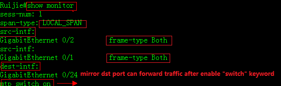
V. Verification
1. This example shows how to verify status ofmonitor session
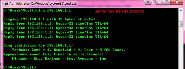
2. This examples verifies that the MonitorServer can visit Internet while monitoring
2.6.2 One to Many Mirror
Note:Only S8600E and N18000 seriesswitch support one to many (or many to many) SPAN so far.
Tips: For those switches that do not supportone to many SPAN, you can apply another fallback method as below:
1. Configure the ordinary many to one SPAN
2. Connect a HUB to the mirror destinationport, so packets floods through the HUB
3. Connect your Monitor Server to the HUB.
HUB can also be a default setting switch.You must assign ports to the remote-vlan and disable the mac-learning feature(enter "no mac-address-learning" config-interface command) andstorm-control feature.
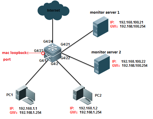
I. Requirements
Core switch copies traffic of G4/1 and G4/2on both directions to Monitor Server 1 connected to port G4/21 and MonitorServer 2 connected to port G4/22
II. Network Topology
III. Configuration Tips
1) Create VLAN 100 as remote-vlan on switch
2) Define G4/1 and G4/2 as source port inmonitor session, and both traffic directions are monitored
3) Create a mac-loopback port, assign thismac-loopback port to Remote vlan and define it as destination port in monitorsession
4) Assign ports G4/21 and G4/22 to Remotevlan 100
Note:
1) Utilize an unused port as mac-loopbackport .You cannot connect cable to this port, even so switch puts link status ofmac-loopback port to up status and port LED is green
2) Don't configure any other commands to themac-loopback port and Don't specify "switch"keyword when configuring monitor session (monitor session 1 destination remotevlan 100 interface gigabitEthernet 4/23 no switch keyword)
IV. ConfigurationSteps
1. Create VLAN 100 as remote-vlan on switch
Ruijie#configure terminal
Ruijie(config)#vlan 100 ------> VLan 100 mustbe dedicated for mirroring
Ruijie(config-vlan)#remote-span
Ruijie(config-vlan)#exit
2. Define G4/1 and G4/2 as source port inmonitor session, and both traffic directions are monitored
Ruijie(config)#monitor session 1 remote-source
Ruijie(config)#monitor session 1 source interfacegigabitEthernet 4/1 both
Ruijie(config)#monitor session 1 source interfacegigabitEthernet 4/2 both
3. Configure G4/23 as mac-loopback port,assign this mac-loopback port to Remote vlan and define it as destination portin monitor session
Ruijie(config)#interface gigabitEthernet 4/23
Ruijie(config-if-GigabitEthernet 4/23)#switchport access vlan100
Ruijie(config-if-GigabitEthernet 4/23)#mac-loopback ------>Don'tconfigure any other commands or connect cable to this port
Ruijie(config-if-GigabitEthernet 4/23)#end
Ruijie(config)#monitor session 1 destination remote vlan 100interface gigabitEthernet 4/23 switch
Ruijie# clear mac-address-table dynamic interfacegigabitEthernet 4/23 ------> clear mac-address-table of this port when finishconfiguring
4. Assign ports G4/21 and G4/22 to Remotevlan 100
Ruijie(config)#interface range gigabitEthernet 4/21-22
Ruijie(config-if-range)#switchport access vlan 100
Ruijie(config-if-range)#end
Ruijie#wr
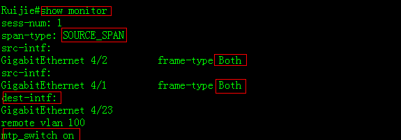
V. Verification
1. This example shows how to verify statusof monitor session
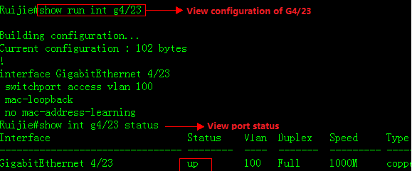
2. This example shows how to displayconfiguration of port G4/23
VI. Script
conft
vlan100
remote-span
exit
monitorsession 1 remote-source
monitorsession 1 source interface gigabitEthernet 4/1 both
monitorsession 1 source interface gigabitEthernet 4/2 both
monitorsession 1 destination remote vlan 100 interface gigabitEthernet 4/23 switch
interfacegigabitEthernet 4/23
switchportaccess vlan 100
mac-loopback
interfacerange gigabitEthernet 4/21-22
switchportaccess vlan 100
2.6.3 Flow-Based Mirroring
Scenario
Flow-based mirroring: During network troubleshooting, when the traffic on the port ishigh, a common mirroring analysis solution may lead to analysis failure due tolimited PC performance, and it would be difficult for the system to capturerequired traffic packets (for example, a traffic packet of a certain MACaddress, or a traffic packet originated by a designated IP address and destinedfor another designated IP address). In this case, you can use the flow-basedmirroring analysis function. If the traffic on the port is too high for themonitoring server or log auditing server deployed on the network to carry outall the data analysis tasks, you can choose to capture specified trafficpackets only.
Function Overview
Port mirroring: You can use the switched port analyzer (SPAN) to replicate packetson a specified port to the port that connects a network surveillance device onthe switch for network monitoring and traffic analysis. You can monitor packetsflow in and out of a source port through SPAN for fast and packet replication.
The SPAN does not change packet informationor affect packet transmission. In addition, the SPAN does not have requirementon the media type for the source and destination ports. Port mirroring can beoptical ports to electrical ports or electrical ports to optical ports. TheSPAN has no requirement on the property of the source and destination ports. Itsupports mirroring from an access port to a trunk port or a trunk port to anaccess port.
Flow-based mirroring: You can define the desired types of traffic packets (for example,PPPOE packets, IP packets on a specified network segment, and HTTP packets onTCP 80) using the ACL. Ruijie switches provide rich ACL functions, and supporttraffic packet matching by L2 frame types, MAC addresses, IP addresses, TCP/UDPports, and ACL80 (the first 80 bytes of a packet). The SPAN captures trafficpackets on the source port according to the defined ACL, and mirrors thetraffic packets to the destination port. Traffic packets not matching thedefined ACL are not mirrored.
Note: The switch supportsflow-based mirroring in the RX direction (inbound on the port) only. Monitoringon the TX (outbound on the port) direction or bi-direction are not supported.
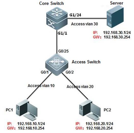
I. Networking Requirements
1. The monitoring server monitors trafficconsumption on the core server by users on the 192.168.10.0/24 network segment.
2. The monitoring server monitors the trafficfrom the core server to the access server.
II. Network Topology
III. Configuration Tips
1. On the core server, configure the ACL toallow users on the network segment 192.168.10.0/24.
2. On the core server, configure the portmirroring function. Set the g1/1 port that connects the access server as thesource port of port mirroring and enable the ACL association.
3. Set the port connecting the monitoringserver (port g1/24) as the destination port of port mirroring.
IV. Configuration Steps
Configure the core server.
Ruijie#configure terminal
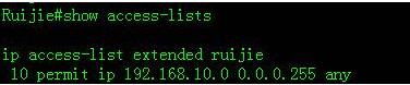
Ruijie(config)#ip access-list extended ruijie ------>CreateACL, named as ruijie
Ruijie(config-ext-nacl)#permit ip 192.168.10.0 0.0.0.255 any
Ruijie(config-ext-nacl)#exit
Ruijie(config)#monitor session 1 source interfacegigabitEthernet 1/1 tx
Ruijie(config)#monitor session 1 source interfacegigabitEthernet 1/1 rx acl ruijie ------> Set the g1/1 port thatconnects the access server as the source port of port mirroring and enable theACL association.
Ruijie(config)#monitor session 1 destination interfacegigabitEthernet 1/24 switch ------> Set the port connectingthe monitoring server (port g1/24) as the destination port of port mirroringand enable switching on the mirroring destination port.
Ruijie(config)#end
Ruijie#wr
V. Verification
1. Check the port mirroring state.
Ruijie(config)#show monitor
sess-num: 1
span-type: LOCAL_SPAN
src-intf:
GigabitEthernet 1/1 frame-type Both
rx acl id 2900
acl name ruijie
dest-intf:
GigabitEthernet 1/24
mtp_switch on ------> Allow mirroring portforwarding data stream
2. Check the ACL.
3.Capture
2.7 Featured commands
1. switchport trunkallowed vlan only x-x
Previously in 10.xversion, all vlans are able to pass through trunk port by default. Engineershave to remove all vlans first, then permit vlan one by one.
By command"switchport trunk allowed vlan only x-x", only allowed vlans are ableto pass through trunk port, you don't need to remove all vlan anymore.
For example:
Ruijie(config-if-GigabitEthernet1/1)#show this
Buildingconfiguration...
switchportmode trunk
switchporttrunk allowed vlan only 1-2
end
2. show this
Previously in 10.xversion, engineers have to execute commands "show run " or "showrun | include xxx" to check configurations.By command "showthis", you can display configurations under current mode directly:
For example :
Ruijie(config)#intmgmt 0
Ruijie(config-if-Mgmt0)#show this
Buildingconfiguration...
!
ipaddress 172.18.10.62 255.255.255.0
gateway172.18.10.1
3. show upgradehistory
Previously in 10.xversion, engineers have to rename firmware as "rgos.bin" beforeupgrading. In addition, there is no historical upgrade records.
Currently, you cangive any name to firmware for convenient management purpose and system mightrecord historical upgrade.
For example:
Ruijie#showupgrade history
LastUpgrade Information:
Time: 2015-04-20 03:02:05
Method: LCOAL
Package Name: N18000_RGOS11.0(2)B1_CM_install.bin
Package Type: Distribution
4. debug sysloglimit
Previously in 10.xversion, at worst, massive system logs printing might crash device after debugis enable.
By command"debug syslog limit time seconds numbers numbers ", system logs printingis limited,
For example:
Ruijie#debugsyslog limit ?
numbers Syslog limited by numbers
reset Syslog reset limit statistics
time Syslog limited by time
5. one keycollection
Previously in 10.xversion, usually engineers have to collect information multiple times whiletrouble shooting which might miss the best opportunity.
By one keycollection, system collects all relevant information in one time.
For example :
Ruijie#debugsupport
Ruijie(support)#tech-support?
console Tech-support information to terminal
package Tech-support information to package
2.8 Typical Feature
2.8.1 VSU
Overview
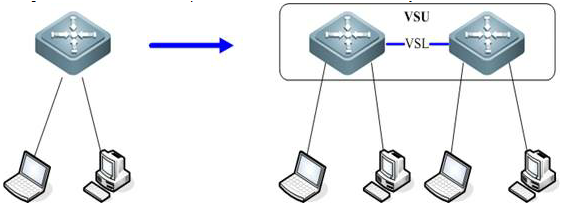
VSU expands the Port Numbers
As figure shown below, when port number on aswitch runs out, you can add one more switch to the VSU to expand port numbers
VSU expands Forwarding Capacity
As figure shown below, you can add one moreswitch to the VSU to expand the global forwarding capacity. For example,forwarding capacity of one switch is 128M pps, and the global forwardingcapacity expands up to 256 M pps when two switches join in a VSU.
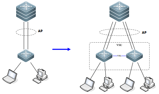
VSU expands Uplink Bandwidth
As figure shown below , you can add one moreswitch to VSU to expand uplink bandwidth to the core switch with the minimumimpact for network topology and configuration.
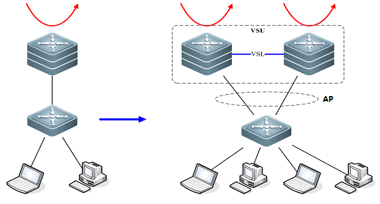
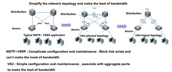
VSU simplifies the Network Topology
As the first figure shown below, this is acommon scenario consisted of MSTP and VRRP features to ensure high available,and redundant ports are blocked to prevent loops.
As the second figure shown below, VSUreduces the complexity of network and enhance the utilization ratio of networkresources. All ports are occupied in the same time.
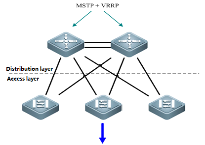
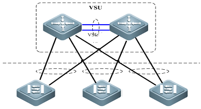
Note:
In thetraditional network, in order to strengthen network reliability, the core layeror distribution layer will generally configure two devices into the dual-coresystem to allow redundant standby, with neighboring devices connecting twolinks to reach the dual-core redundant system. Such typical traditional networkarchitecture is shown in the following figure. The redundant networkarchitecture increases the complexity of network design and operations, whilethe enormous standby links also reduce the utilization ratio of networkresources and decrease the rate of return on investment.
VSU (VirtualSwitching Unit) is a common network virtualization technology combining twoswitches into a single virtual switch, thus reducing the complexity of networkand enhancing the utilization ratio of network resources.
Role of Chassis:
Each switch in aVSU are called VSU member and there're three VSU roles for VSU member based ondifferent features:
1) Active:The active chassis controls the entire VSU system
2) Standby: The standby chassis take charge of the control if themain chassis fails
VSU Domain ID:
VSU Domain IDranges from 1 to 255, and the default value is 100. Only VSU members with thesame Domain ID can establish a VSU.
VSU Chassis ID:
The value ofChassis id can be 1 or 2.The default value is 1.
In standalonemode, port number takes 2-dimension format (for example, GigabitEthernet 2/3) ;In VSU mode , port number takes 3-dimension format (for example ,GigabitEthernet 1/2/3).
The firstnumber(GigabitEthernet1/2/3) indicatesthe chassis ID and the last two numbers (GigabitEthernet1/2/3)indicate the slot number and port number. So chassis ID of each VSU member mustbe different.
In addition, iftwo VSU chassises have the same chassis ID, VSU system recalculates a newchassis ID for them.
VSU Chassis Priority:
The value ofchassis priority ranges from 1 to 255, and the default value is 100. A higherpriority indicates a higher priority to become the active chassis.
In addition,chassis priority consists of configuring priority and running priority. Runningpriority doesn't change when administrator changes the configuring prioritywhen VSU is running .Running priority changes when administrator savesconfiguration and reloads the VSU.
VSL
Since two chassisjointly forms a network entity in VSU system, they need to share controlinformation and partial data streams. VSL (Virtual switching link) is a speciallink between two chassis for transmitting control information and data streams
The VSL acts asan aggregation port. Its member port count is unlimited, and these member portscan reside on line cards in different slots. For the VSLtransferred traffic,load balancing is performed among these member ports according to the trafficbalancing algorithm.
Currently, 10-GBor 40-GB ports can become member ports of the VSL, while 1-GB ports cannot.Besides, a line card can hold physical member ports of the VSL as well ascommon data service ports.
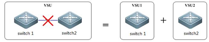
VSL Interruption:
As figure shownbelow, VSL Interruption occurs when the VSL fails and both VSU membersdisconnect
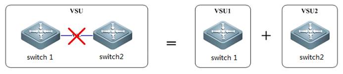
VSU Combination:
As figure shownbelow, VSU Combination occurs when both VSU members with the same Domain IDestablish a VSU
Swtich Working Mode:
Switch workingmode includes: standalone mode and VSU mode, and the default mode is standalonemode
VSU VSL Connection medium:
Different switchvaries.
For example, youcan only configure VSL on S8600E series switches on 10G/40G optical ports.
VSL Detection:
VSL detectionstarts to detect peer chassis once VSU members boot and after VSL links comeup, Topology Discovery begins.
Topology Discovery:
VSU membersacquire global VSU network topology by flooding VSU hello packets through VSL.VSU Hello packets carry topology information including chassis ID, priority,MAC, VSL port etc.
VSU Role Electionstarts when Topology Discovery completes.
VSU Role Election:
The activechassis election mechanism operates as below:
Current hostfirst
The higherpriority first
The lower MACaddress first
The slave chassiselection mechanism is as follows:
The nearest tomain first
The higherpriority first
The lower MACaddress first
After finishingelection, active chassis floods Convergence packets to the overall VSU, thenVSU establishment completes.
Dual ActiveDetection:
When VSL is disconnected, the slavechassis will be switched to main chassis. If the former main chassis is stillrunning, then the existing two chassis will both become the main chassis. Sincethe configurations are completely same, a series of problems such IP addressconflict will arise in the LAN. VSU must detect dual main chassis and takerestoration measures.
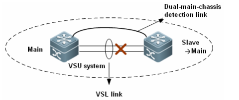
As shown in the figure above, whendeploying the VSU system, you need to configure an independent physical linkbetween chassis in addition to the VSL. The physical link is sued to transferdual-main-chassis packets when the VSL is disconnected. It is calleddual-main-chassis detection link. Ports connecting this link can be used totransfer only dual-main-chassis detection packets. You can run a CLI command tospecify certain ports as the dual-main-chassis detection ports.
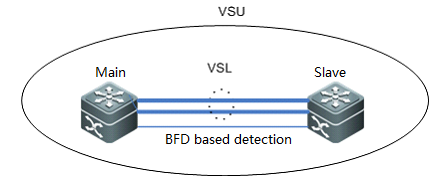
After dual main chassis are detected,generally, one chassis enters the recovery mode to avoid network abnormity. TheVSU system supports the Bidirectional Forwarding Detection (BFD) and AP-baseddetection.
1) BFD basedDetection:A port of BFD for dual main chassis must bea L3 physical port. Ports of other modes will not do. When you transform theport of BFD for dual main chassis from a L3 port into a port of other modes,the detection is automatically cleared and a prompt is displayed. Here, theextended BFD is used. That is, existing BFD configuration and display commandscannot be used to configure dual-main-chassis detection ports.
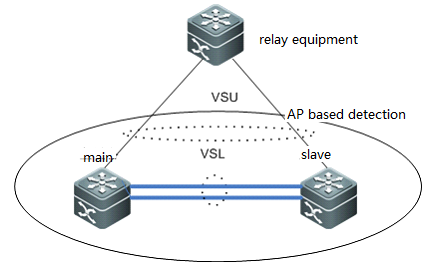
2) AP basedDetection:The AP-based mechanism of detecting dualmain chassis is similar as that based on BFD. When the VSL is disconnected andtwo main chassis occur, the two main chassis send private protocol packets toeach other for detecting dual main chassis. The difference from BFD baseddetection is AP-based Detection configures on the AP links between VSU and onerelay equipment as figure shown below, and this relay equipment shall supportforward private detection packets.
Recovery mode:
When the main chassis is in the recoverymode, all services ports except the following ports must be disabled:
VSL port: when the main chassis in therecovery mode detects that the VSL is UP again, the chassis resets itself, andjoins the VSU system in the hot standby mode, becoming the new slave chassis.
MGMT port: You can use this port toperform remote management no matter the main chassis is in the recovery mode ornot.
Exception port: You can specify certainports as exception ports, which will not be disabled when the main chassisenters the recovery mode. Exception port: You can specify certain ports asexception ports, which will not be disabled when the main chassis enters therecovery mode. To configure exception ports, run the dual-active excludeinterface interface-name command.
In the dual-main-chassis mode or when amain chassis enters the recovery mode, the simplest recovery
Solution is to reconnect the VSL. If VSL isnot reconnected, but the main chassis in the recovery mode is manuallyrestarted, the system enters dual-main-chassis state again when after therestart succeeds.
2.8.1.1 Configuringbasic VSU
1. Configuring active and standby VSU members
Active switch:
Switch1#configure terminal
Enterconfiguration commands, one per line. End with CNTL/Z.
Switch1(config)#switch virtual domain 1
Switch1(config-vs-domain)#switch 1
Switch1(config-vs-domain)#switch 1 priority 200 ------>Priority is 100 by default , switch with the higherpriority becomes the active chassis
Switch1(config-vs-domain)#exit
Switch1(config)#vsl-aggregateport 1 ------>VSL is the heartbeat and traffic channel between 2 VSUmembers. You must configure at least 2 pair of VSL
Switch1(config-vsl-ap-1)#port-member interface TenGigabitEthernet 2/1
Switch1(config-vsl-ap-1)#port-member interface TenGigabitEthernet 2/2
Switch1(config-vsl-ap-1)#exit
Standby switch:
Switch2#configure terminal
Enterconfiguration commands, one per line. End with CNTL/Z.
Switch2(config)#switch virtual domain 1 ------>domain ID must be the same to that of active chassis
Switch2(config-vs-domain)#switch 2 ------>switch ID must be different from that of activechassis
Switch2(config-vs-domain)#switch 2 priority 150
Switch2(config-vs-domain)#exit
Switch2(config)#vsl-aggregateport 1
Switch2(config-vsl-ap-1)#port-member interface TenGigabitEthernet 2/1
Switch2(config-vsl-ap-1)#port-member interface TenGigabitEthernet 2/2
Switch2(config-vsl-ap-1)#exit
2. Connect VSL cable and confirm that linkscome up
3. Save configuration and convert both VSUmembers to virtual mode at the same time
Active switch
Switch1#wr
Switch1#switch convert mode virtual ------>convert switch working mode fromstandalone mode to virtual mode
Areyou sure to convert switch to virtual mode[yes/no]:yes
Doyou want to recovery“config.text”from“virtual_switch.text”[yes/no]:no
Standby switch
Switch2#wr
Switch2# switch convertmode virtual
Areyou sure to convert switch to virtual mode[yes/no]:yes
Doyou want to recovery“config.text”from“virtual_switch.text”[yes/no]:no
Both VSU members reloads automatically
Attention: Be patient and it costsabout 10 minutes to finish building VSU.
System prints logs continuouslyduring next 10 minutes as below if VSL links failed or peer switch doesn'treload yet:
*Aug 6 13:17:17:%VSU-5-RRP_TOPO_INIT: Topology initializing, please wait for a moment
*Aug 6 13:18:17:%VSU-5-RRP_TOPO_INIT: Topology initializing, please wait for a moment.
4. Verification
1. When VSUcompletes, you can manage VSU on active chassis.
2. You canidentify the active switch by viewing the Primary LED on the front main boardwhich is solid green
3. When VSUcompletes, you can no longer manage VSU on standby chassis through console portby default.
Ruijie#show switch virtual
Switch_id Domain_id Priority Position Status Role
--------------------- ---------- ---------- -------- ---------
1(1) 1(1) 200(200) LOCAL OK ACTIVE------>active
2(2) 1(1) 150(150) REMOTE OK STANDBY------>standby
Ruijie#shversion slot
DevSlot Configured Module Online Module User Status Software Status --- ---- ----------------- ----- --------------
11 none none
12 M8606-24SFP/12GT M8606-24SFP/12GT installed none
13 M8606-2XFP M8606-2XFP uninstalled cannot startup
14 M8606-24GT/12SFP M8606-24GT/12SFP installed ok
1M1 M8606-CM M8606-CM master
1 M2
2.8.1.2 Configuring VSU optimization
Overview
1. When VSL is disconnected, the standbychassis will be switched to active chassis. If the former active chassis isstill running, then the existing two chassis will both become the activechassis. Since the configurations are completely same, a series of problemssuch IP address conflict will arise in the LAN. VSU must detect dual-active chassisand take restoration measures.
2. After enable dual-active detection , systemdetects dual-active via control packets between BFD dedicated link and puts onechassis which has lower priority into recovery mode ,all port ,except for VSLport, MGMT port and exception port that administrator specifies (reserved fortelnet), are mandatory shutdown
When dual-active occurs, dual-active detection ensuresthe stability and high availability of your network. (youmust use redundant connection to connect other switches to VSU . In addition,you must connect one link to the active chassis, the other to standby chassis)
I. ConfigurationSteps
1. Configuring Dual-active Detections
Ruijie(config)#interface gi2/4/2
Ruijie(config-if)#no switchport ------>BFD detection must be applid on a Layer 3 port
Ruijie(config-if)#exit
Ruijie(config)#interface gi1/4/2
Ruijie(config-if)#no switchport
Ruijie(config-if)# exit
Ruijie(config)# switch virtual domain 1
Ruijie(config-vs-domain)#dual-active detection bfd ------>enable BFD feature
Ruijie(config-vs-domain)#dual-active pair interface gi1/4/2 interface gi2/4/2 ------>configurea pair of BFD detection ports
Ruijie(config-vs-domain)#dual-active exclude interface ten1/1/2 ------>configure theexception port
Ruijie(config-vs-domain)#dual-active exclude interface ten2/1/2
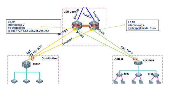
2.8.1.3 Configuring AP in VSU
Overview
Inter-chassis aggregate port (AP) groupincludes member ports of two VSU chassis. Inter-chassis AP can connect to alldevices (such as server, switch and router) supporting port aggregationfunction.
Inter-chassis AP allows load balancing ofinter-chassis data streams. For example, when data streams enter from mainchassis into VSU system, VSU will give preference to member ports located inthe main chassis. This feature guarantees that some unnecessary data streamsare not transmitted over VSL, thus reducing the load pressure of VSL.
The following figure shows the typicalapplication of AP in a VSU.
I. ConfigurationSteps
1. Configuring layer 3 AP on VSU:
Ruijie(config)#interfaceaggregateport 2
Ruijie(config-if-AggregatePort2)#no switchport
Ruijie(config-if-AggregatePort2)#description link-to-xxxx
Ruijie(config-if-AggregatePort2)#ip add 172.16.1.6 255.255.255.252
Ruijie(config-if-AggregatePort2)#exit
Ruijie(config)#interfaceten 1/3/1
Ruijie(config-if-TengabitEthernet1/3/1)#no switchport
Ruijie(config-if-TengabitEthernet1/3/1)#description linktoyyyy
Ruijie(config-if-TengabitEthernet1/3/1)#port-group 2
Ruijie(config-if-TengabitEthernet1/3/1)#exit
Ruijie(config)#interfaceten 2/3/1
Ruijie(config-if-TengabitEthernet2/3/1)#no switchport
Ruijie(config-if-TengabitEthernet2/3/1)#description link-to-yyyy
Ruijie(config-if-TengabitEthernet2/3/1)#port-group 2
Ruijie(config-if-TengabitEthernet2/3/1)#exit
2. Configuring layer 2 AP on VSU:
Ruijie(config)#interfaceaggregateport 4
Ruijie(config-if-AggregatePort4)#switchport mode trunk
Ruijie(config-if-AggregatePort4)#switchport trunk allowed vlan remove xxxx ----->prune trunk portbased on requirement
Ruijie(config-if-AggregatePort4)#description linktoxxxx
Ruijie(config-if-AggregatePort4)#exit
Ruijie(config)#interfacegigabitEthernet 1/4/1
Ruijie(config-if-GigabitEthernet1/4/1)#port-group 4
Ruijie(config-if-GigabitEthernet1/4/1)#description link-to-yyyy
Ruijie(config-if-GigabitEthernet1/4/1)#exit
Ruijie(config)#interfacegigabitEthernet 2/4/1
Ruijie(config-if-GigabitEthernet2/4/1)#port-group 4
Ruijie(config-if-GigabitEthernet2/4/1)#description link-to-yyyy
Ruijie(config-if-GigabitEthernet2/4/1)#exit
2.8.1.4 Verifying VSU
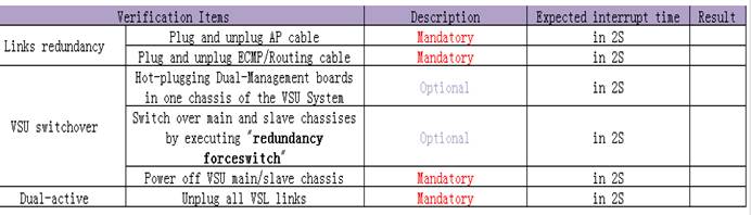
2.8.2 1X-Web Authentication
2.8.2.1 Secure Channel, Authentication-Free, andEmergency Channel
Features
Secure channel: Generally, after 1Xauthentication is deployed, data packets from unauthenticated user ports arediscarded. The secure channel allows users access designated websitesunauthenticated. It can be deployed to facilitate client distribution, backdoorreservation for leaders and terminals that do not support authentication (forexample, printers and all-purpose terminals).
Emergency channel: In an 1X authenticationscenario with only one Radius server, all users fail to access the Internetonce the Radius server fails, services will be seriously affected. In thatcase, authentication configuration must be cancelled on all the ports one byone to recover services. If an emergency channel is deployed, the switch allowsusers access the Internet without authentication when authentication failsmultiple times or the Radius server is considered dead.
I. NetworkingRequirements
1. The 1X function is enabled on the coreserver for resource access authentication on managed users.
2. Authenticated users can access allresources while unauthenticated users can access only certain Intranetresources.
3. Authentication-free access to intranetresources is enabled for some users (PC2).
4. When the active Radius server fails tofunction normally, user authentication is switched to the backup Radius server.When both active and standby Radius servers fail, managed users can accessresources without authentication (through an emergency channel).
II. Network Topology
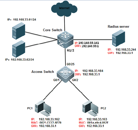
III. ConfigurationTips
1. On the core server, enable AAA andconfigure the Radius server and key associated parameters.
2. On the Radius server, configure therelated parameters. (In this example, the SAM is used as the Radius server.)
3. Configure a professional ACL to implementserver access before user authentication.
4. The core switch, managed users, and theRadius server can be on different network segments, so long as the core switchcan properly communicate with the Radius server and the clients can reach thecontrolled ports on the core switch via the access switch.
5. Configure the parameters for thecommunication between the switch and the Radius server to deploy an emergencychannel.
IV. ConfigurationSteps
Configure the core server.
1. Basic dot1x configuration
Ruijie>enable
Ruijie#configure terminal
Ruijie(config)#aaa new-model ------>trun on aaaswitch
Ruijie(config)#radius-server host 192.168.33.244 ------>configureradius server
Ruijie(config)#radius-server host 192.168.33.245 ------>configurebackup radius server
Ruijie(config)#radius-server key ruijie ------>configureradius key
Ruijie(config)#aaa authentication dot1x ruijie group radius none ------> Define an IEEE802.1x authentication method list.
Ruijie(config)#aaa accounting network ruijie start-stop groupradius ------> Define the AAA network accounting method list.
Ruijie(config)#aaa accounting update periodic 15 ------> Setthe account update function.
Ruijie(config)#dot1x authentication ruijie ------>802.1X to select the authentication method list
Ruijie(config)#dot1x accounting ruijie ------>802.1X to select the accounting method list
Ruijie(config)#interface gigabitEthernet 1/2
Ruijie(config-if-GigabitEthernet 1/2)#switchport mode trunk
Ruijie(config-if-GigabitEthernet 1/2)#dot1x port-controlauto ------> Enable 802.1X authentication on the interface
Ruijie(config-if-GigabitEthernet 1/2)#ip add 192.168.33.161255.255.255.0 ------> configure switch ip address
Ruijie(config-if-GigabitEthernet 1/2)#end
Ruijie#write ------> save configuration
2. Enable the secure channel function
Ruijie(config)#expert access-list extended ruijie
Ruijie(config-exp-nacl)#permit arp any any any any any ------>makethe ip and arp packets free authentication
Ruijie(config-exp-nacl)#permit ip any any host 192.168.33.61any ------> To allow access to the home page of the site beforeauthentication
Ruijie(config-exp-nacl)#permit ip any any host 192.168.33.62any ------> To allow access to the home page of the site beforeauthentication
Ruijie(config-exp-nacl)#permit ip any any host 192.168.33.244any------> To allow access to the home page of the site before authentication
Ruijie(config-exp-nacl)#permit host 192.168.33.163 host001a.a9c4.062f any any------> This host implements authentication free
Ruijie(config-exp-nacl)#exit
Ruijie(config)#security global access-group ruijie
1x free authentication description
There are two ways to achieve user authentication: (1)configure the security channel to put the IP or MAC address; 2, configure thefree VLAN authentication will be the corresponding VLAN users free ofauthentication
Plan 1:Configure security channel,there are three methods:
Method 1:permit host ip address
expert access-list extended no1x
10 permit arp any any any any any
20 permit ip host 192.168.1.23 any anyany ------->permithost ip address
security global access-group no1x
method 2:permit host mac address
expert access-list extended no1x
10 permit arp any any any any any
30 permit ip any host 0010.123c.513d any any ------->permithots mac address
security global access-group no1x
method 3:permit ip+mac
expert access-list extended no1x
10 permit arp any any any any any
40 permit ip host 192.168.1.23 host 0010.123c.513d any any ------->permitip and mac address
security global access-group no1x
Plan 2:Configure direct-vlan
Configuration command:direct-vlan 1-20// direct-vlan can take effect on both 1xauthentication and web authentication
Notes:
If the secure channel (inpriority over 1x authentication) is enabled, user ARP packets must be allowedto pass. In this way, users can communicate with the gateway. As the securechannel has higher priority, the anti ARP spoofing function will becomeinvalid.
Solution: Do not permit allARP packets. Permit only ARP packets destined for the gateway. In this way, ARPcheck is implemented and ARP spoofing among users are prevented. However, ARPspoofing is not completely prevented, because users can still spoof anotheruser on the gateway.
Ruijie(config)#expert access-list extended permit1x
Ruijie(config-exp-nacl)#permit ip any any host 192.168.1.254any ------> To allow access to the home page of the site beforeauthentication
Ruijie(config-exp-nacl)#permit arp any any any any any ------>Allow ARP message interaction between a user and a gateway
Ruijie(config)#security global access-group permit1x
Ruijie(config-exp-nacl)#permit arp any any any any host192.168.33.1
3. You can change the time parameterbetween the switch and the Radius server to switch the authentication method.For example, the configuration "aaa authentication dot1x ruijie groupradius none" indicates that authentication by the active Radius server isimplemented first, is switched to the backup Radius server if the active Radiusserver does not respond in a specified period, and is switched to noneauthentication mode if both the active and backup Radius servers fail torespond.
Ruijie(config)#radius-server timeout 2 ------>Specify the waiting time before the router resend request (2 s by default)
Ruijie(config)#radius-server retransmit 2 ------>Specify the times of sending requests before the router confirms Radius invalid(3 by default)
Ruijie(config)#radius-server dead-criteria time 6 tries 3 ------>definethe dead-criteria time and tries of the server
Ruijie(config)#radius-server deadtime 5 ------>Specify the waiting time before the server is considered dead in case of noresponse to the request sent by the device (5 minutes by default).
Ruijie(config)#dot1x timeout server-timeout 20
dot1x timeout indicatesthe timeout period of 1x authentication. The parameter is independent from theRadius timeout period (radius timeout*). However, radius timeout*(retransmit+1) must be smaller than dot1x timeout server-timeout.Otherwise, the emergency channel does not take effect. In this example,2*(2+1)=6s, which is smaller than 20s, and therefore, the emergency channel iseffective.
V. Verification
1. Before authentication, users can accessthe resources inside the secure channel, but can not access the resourcesinside the non secure channel
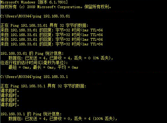
The same can also be verified, the securitychannel is free to authenticate users of IP and MAC, the user can alsocommunicate properly.
2、When the radius server hangs, the user can achieve escape function
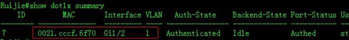
Check the user info.
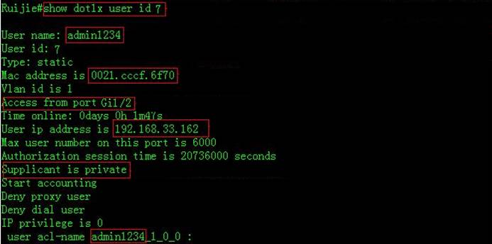
3. open debug radius event, you can see theentire process of an escape function:
Ruijie#debug radius event
Ruijie#*Mar 16 18:07:20: %7: [radius] aaa req authenticationto group radius
*Mar 16 18:07:20: %7: __rds_add_attr type = 24 len = 0
*Mar 16 18:07:20: %7: [radius] 16 send
*Mar 16 18:07:20: %7: pkt len 676 code 1 id 16
*Mar 16 18:07:20: %7: calcu msg auth ok
*Mar 16 18:07:20: %7: [radius] radius access requests(12). ------>sent access-request for the first time
*Mar 16 18:07:22: %7: [radius] user 16 retry
*Mar 16 18:07:22: %7: [radius] 16 send
*Mar 16 18:07:22: %7: pkt len 676 code 1 id 16
*Mar 16 18:07:22: %7: calcu msg auth ok
*Mar 16 18:07:22: %7: [radius] radius access requestsretransmissions(18) timeout(18). ------>timeout for the first time after 2seconds
*Mar 16 18:07:24: %7: [radius] user 16 retry
*Mar 16 18:07:24: %7: [radius] 16 send
*Mar 16 18:07:24: %7: pkt len 676 code 1 id 16
*Mar 16 18:07:24: %7: calcu msg auth ok
*Mar 16 18:07:24: %7: [radius] radius access requestsretransmissions(19) timeout(19). ------> timeout for the second time after4 seconds
*Mar 16 18:07:26: %7: [radius] user 16 retry
*Mar 16 18:07:26: %7: [rds_user] rds delete user, state 2,atype 0
*Mar 16 18:07:26: %7: [rds_user] rds free user id 7, pkid16 ------> timeout for the third time after 6 seconds
*Mar 16 18:07:26: %AAA-7-FAILOVER: Failing over from 'dot1x'for client 0021.cccf.6f70 on Interface GigabitEthernet 0/1.
*Mar 16 18:07:26: %7: [radius] aaa req accounting to groupradius
*Mar 16 18:07:26: %7: [accounting] acct len 116
*Mar 16 18:07:26: %7: __rds_add_attr type = 25 len = 0
*Mar 16 18:07:26: %7: [radius] 17 send
*Mar 16 18:07:26: %7: [radius] radius acc requests(5) andpending(3).
*Mar 16 18:07:28: %7: [radius] user 17 retry
*Mar 16 18:07:28: %7: [radius] 17 send
*Mar 16 18:07:28: %7: [radius] radius acc retransmissions(5)timeout(5).
*Mar 16 18:07:30: %7: [radius] user 17 retry
*Mar 16 18:07:30: %7: [radius] 17 send
*Mar 16 18:07:30: %7: [radius] radius acc retransmissions(6)timeout(6).
*Mar 16 18:07:32: %7: [radius] user 17 retry
*Mar 16 18:07:32: %7: [rds_user] rds delete user, state 2,atype 2
*Mar 16 18:07:32: %7: [rds_user] rds free user id 7, pkid 17
2.8.3 MSTP+VRRP
2.8.3.1 MSTP+VRRP Overview
Two common deployment patterns ofMSTP+VRRP
1. MSTP with single instance:
As figure shown below, SW1 is the root bridge for MSTPinstance 0 to which all vlans are mapped and master VRRP gateway for all vlans.This deployment patterns of MSTP is almost the same to RSTP.
Merit: Easier maintenance andimplementation
Demerit:SW2 is the second root andbackup VRRP gateway which doesn't forward any traffic .It is a waste of networkresource.
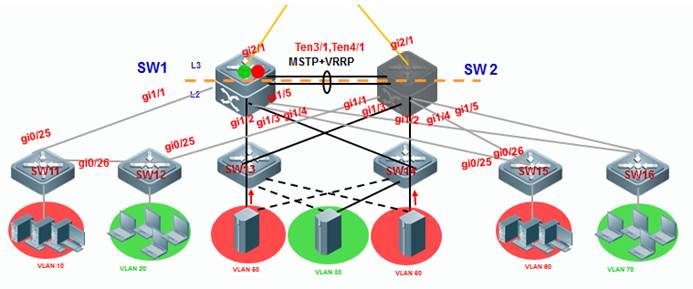
2. MSTP with Multiple instances:
As figure shown below, SW1 is the root bridge for MSTPinstance 1 and secondary root for instance
2. SW2 is Root Bridge for MSTP instance 2 and secondaryroot for instance 1. MSTP instance 1 includes VLAN 10, 60 and 80 and instance 2includes VLAN 20, 30 and 70.
SW1 is the master VRRP gateway for VLAN 10, 60 and 80and the backup VRRP gateway for VLAN 20, 30 and 70. SW2 is the master VRRPgateway for VLAN 20, 30 and 70 and the backup gateway for VLAN 10, 60 and 80.
Merit:Fully occupy networkresource
Demerit:More complicatedconfiguration and maintenance than MSTP with single instance
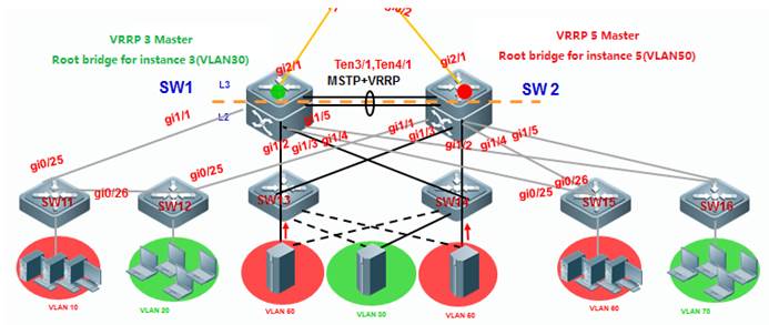
2.8.3.2 Configuring MSTP with single instance
Note:
The deployment pattern of "MSTP +VRRP" is replaced by deployment pattern of VSU day by day and we suggestyou to apply VSU if possible. Even so, deployment pattern of "MSTP +VRRP" is still a fallback method to ensure a redundant and reliablenetwork if core and distribution switches don't support VSU
We suggest you to remove someinterconnection links first to avoid a Layer 2 loop
I. Network Topology

SW1 is the master VRRP gateway for users on all vlans,and SW2 is the backup VRRP gateway for users on all vlans. Connect SW1 and SW2through an Aggregate port to ensure reliability and configure this AP as Trunkport.
The IP address of SW1 on VLANs from 10 to 80 are192.168.10.1 to 192.168.80.1 , and IP address of SW2 on VLANs from 10 to 80 are192.168.10.2 to 192.168.80.2 , and VRRP IP address are 192.168.10.254 to192.168.80.254.
II. ConfigurationSteps
Configuring SW1
Ruijie#configterminal
Ruijie(config)#spanning-treemst 0 priority 0 ------>instance id=0 , priority=0(The lower the number, themore likely the switch will be chosen as the root bridge) by default , allvlans are mapped to instance 0 .
Ruijie(config)#spanning-tree ------>enable STP feature and the default STP mode is MSTP
Ruijie(config)#e xit
Configure MSTP
Configuring AP
Ruijie#configterminal
Ruijie(config)#interfaceaggregateport 1
Ruijie(config-if-AggregatePort1)#switchport mode trunk
Ruijie(config-if-AggregatePort1)#exit
Ruijie(config)#interfacetengigabitEthernet 3/1
Ruijie(config-if-TenGigabitEthernet3/1)#port-group 1
Ruijie(config-if-TenGigabitEthernet3/1)#exit
Ruijie(config)#interfacetengigabitEthernet 3/2
Ruijie(config-if-TenGigabitEthernet3/2)#port-group 1
Ruijie(config-if-TenGigabitEthernet3/2)#exit
Ruijie(config)#interfacerange gigabitEthernet 1/1-5
Ruijie(config-if-range)#switchportmode trunk ----->don't forget to prune trunk port
Configuring VRRP
Ruijie(config)#vlan10
Ruijie(config)#intervlan 10
Ruijie(config-if-VLAN10)#ip address 192.168.10.1 255.255.255.0
Ruijie(config-if-VLAN10)#vrrp 10 ip 192.168.10.254
Ruijie(config-if-VLAN10)#vrrp 10 priority 120 ------> vrrp group id=10 , priorityvalue=120 (the bigger the number , the more likely the switch will be chosen asthe master ,and default value is 100)
Ruijie(config-if-VLAN10)#exit
Ruijie(config)#vlan20
Ruijie(config)#intervlan 20
Ruijie(config-if-VLAN20)#ip address 192.168.20.1 255.255.255.0
Ruijie(config-if-VLAN20)#vrrp 20 ip 192.168.20.254
Ruijie(config-if-VLAN20)#vrrp 20 priority 120
Ruijie(config-if-VLAN20)#exit
...........configurationof VLAN 30 ~ VLAN 70 are omitted............
Ruijie(config)#vlan80
Ruijie(config)#intervlan 80
Ruijie(config-if-VLAN80)#ip address 192.168.80.1 255.255.255.0
Ruijie(config-if-VLAN80)#vrrp 80 ip 192.168.80.254
Ruijie(config-if-VLAN80)#vrrp 80 priority 120
Ruijie(config-if-VLAN80)#exit
Configuring SW2
Ruijie#configterminal
Ruijie(config)#spanning-treemst 0 priority 4096 ------>instance id=0 , priority=4096(The lower the number,the more likely the switch will be chosen as the root bridge) by default , allvlans are mapped to instance 0
Ruijie(config)#spanning-tree ------>enable STP feature and default mode is MSTP
Ruijie(config)#exit
Configuring AP
Ruijie#configterminal
Ruijie(config)#interfaceaggregateport 1
Ruijie(config-if-AggregatePort1)#switchport mode trunk
Ruijie(config-if-AggregatePort1)#exit
Ruijie(config)#interfacetengigabitEthernet 3/1
Ruijie(config-if-TenGigabitEthernet3/1)#port-group 1
Ruijie(config-if-TenGigabitEthernet3/1)#exit
Ruijie(config)#interfacetengigabitEthernet 3/2
Ruijie(config-if-TenGigabitEthernet3/2)#port-group 1
Ruijie(config-if-TenGigabitEthernet3/2)#exit
Ruijie(config)#interfacerange gigabitEthernet 1/1-5
Ruijie(config-if-range)#switchportmode trunk ----->don't forget to prune trunk port
Configuring VRRP
Ruijie(config)#vlan10
Ruijie(config)#intervlan 10
Ruijie(config-if-VLAN10)#ip address 192.168.10.2 255.255.255.0
Ruijie(config-if-VLAN10)#vrrp 10 ip 192.168.10.254 ------>vrrp groupid=10 , priority value remains default setting(the bigger the number , the morelikely the switch will be chosen as the master ,and default value is 100)
Ruijie(config-if-VLAN10)#exit
Ruijie(config)#vlan20
Ruijie(config)#intervlan 20
Ruijie(config-if-VLAN20)#ip address 192.168.20.2 255.255.255.0
Ruijie(config-if-VLAN20)#vrrp 20 ip 192.168.20.254
Ruijie(config-if-VLAN20)#exit
...........configurationof VLAN 30 ~ VLAN 70 are omitted............
Ruijie(config)#vlan80
Ruijie(config)#intervlan 80
Ruijie(config-if-VLAN80)#ip address 192.168.80.2 255.255.255.0
Ruijie(config-if-VLAN80)#vrrp 80 ip 192.168.80.254
Ruijie(config-if-VLAN80)#exit
Configuring SW11,SW12,S13,S14,S15,S16
Ruijie#configterminal
Ruijie(config)#interfacerange gigabitEthernet 0/25-26
Ruijie(config-if-range)#switchportmode trunk
Ruijie(config-if-range)#exit
Ruijie(config)#spanning-tree ------>enableSTP feature and default mode is MSTP
Ruijie(config)#exit
Ifwe want to manully conduct MSTP to put G0/25 on SW11 and SW12 in forwardingstate , we can assign a higher cost value to G0/26 , then MSTP blocks G0/26.(If a loop occurs, MST uses the path cost when selecting an interface to placeinto the forwarding state. A lower path cost represents higher-speedtransmission)
Ruijie(config)#interfacegi0/26
Ruijie(config-if-GiagaEthernet0/26)#spanning-tree cost 200000 ------>the default value is derived fromthe media speed of the interface , and the cost value of an 1000M port is 20000
Ruijie(config-if-GiagaEthernet0/26)#exit
Connectting cable and verifying status ofSTP and VRRP
1. This example displays that SW1 is theroot bridge
SW1:
Ruijie#showspanning-tree
StpVersion: MSTP
SysStpStatus: ENABLED
MaxAge: 20
HelloTime: 2
ForwardDelay: 15
BridgeMaxAge: 20
BridgeHelloTime: 2
BridgeForwardDelay: 15
MaxHops:20
TxHoldCount: 3
PathCostMethod: Long
BPDUGuard: Disabled
BPDUFilter: Disabled
LoopGuardDef : Disabled
######mst 0 vlans map : ALL
BridgeAddr: 1414.4b19.ecc0 ------>local MAC address
Priority:0
TimeSinceTopologyChange: 12d:0h:19m:46s
TopologyChanges: 0
DesignatedRoot: 0.1414.4b19.ecc0 ------>root MAC address
RootCost: 0
RootPort: 0
CistRegionRoot: 0.1414.4b19.ecc0
CistPathCost: 0
2. This example displays that SW1 is theVRRP master
Ruijie#showvrrp 10
VLAN10 - Group 10
State is Master
Virtual IP address is 192.168.10.254 configured
Virtual MAC address is 0000.5e00.010a
Advertisement interval is 1 sec
Preemption is enabled
min delay is 0 sec
Priority is 120
Master Router is 192.168.10.1 (local), priority is 120
Master Advertisement interval is 1 sec
Master Down interval is 3.53 sec
Ruijie#showvrrp brief
Interface Grp Pri timer Own Pre State Master addr Group addr
VLAN10 10 120 3.53 - P Master 192.168.10.1 192.168.10.254
VLAN20 20 120 3.53 - P Master 192.168.20.1 192.168.20.254
VLAN30 30 120 3.53 - P Master 192.168.30.1 192.168.30.254
VLAN40 40 120 3.53 - P Master 192.168.40.1 192.168.40.254
VLAN50 50 120 3.53 - P Master 192.168.50.1 192.168.50.254
VLAN60 60 120 3.53 - P Master 192.168.60.1 192.168.60.254
VLAN70 70 120 3.53 - P Master 192.168.70.1 192.168.70.254
VLAN80 80 120 3.53 - P Master 192.168.80.1 192.168.80.254
3. This example displays that SW1 is theroot bridge on SW2
SW2:
Ruijie#showspanning-tree
StpVersion: MSTP
SysStpStatus: ENABLED
MaxAge: 20
HelloTime: 2
ForwardDelay: 15
BridgeMaxAge: 20
BridgeHelloTime: 2
BridgeForwardDelay: 15
MaxHops:20
TxHoldCount: 3
PathCostMethod: Long
BPDUGuard: Disabled
BPDUFilter: Disabled
LoopGuardDef : Disabled
######mst 0 vlans map : ALL
BridgeAddr: 00d0.f834.ea70 ------>SW2 MAC address
Priority:4096
TimeSinceTopologyChange: 0d:0h:9m:2s
TopologyChanges: 6
DesignatedRoot: 0000.1414.4b19.ecc0 ------> root MAC address(SW1)
RootCost: 0
RootPort: 3
CistRegionRoot: 0000.1414.4b19.ecc0
CistPathCost: 20000
4. This example displays that SW2 is theVRRP Backup
CistPathCost: 20000 Ruijie#show vrrp 10
VLAN10 - Group 10
State is Backup
Virtual IP address is 192.168.10.254 configured
Virtual MAC address is 0000.5e00.010a
Advertisement interval is 1 sec
Preemption is enabled
min delay is 0 sec
Priority is 100
Master Router is 192.168.10.1 , priority is 120
Master Advertisement interval is 1 sec
Master Down interval is 3 sec
5. This exmaple displays how to verify rootbridge on SW11 and SW12 and whether MSTP has blocked G0/26 as per design.
Ruijie#showspanning-tree summary
Spanningtree enabled protocol mstp
MST0 vlans map : ALL
Root ID Priority 0
Address 1414.4b19.ecc0 ------>root bridge MAC address
this bridge is root
Hello Time 2 sec Forward Delay 15 sec Max Age 20 sec
Bridge ID Priority 32768
Address 00d0.f8b5.0a0b ------>local MAC address
Hello Time 2 sec Forward Delay 15 sec Max Age 20 sec
Interface Role Sts Cost Prio Type OperEdge
-------------------- --- ---------- -------- ----- ---------------
Gi0/25 Root FWD 200000 128 P2p False ------>root port
Gi0/26 Altn BLK 200000 128 P2p ------>blocked port
When you connect Ruijie switch toother vendors, pay attention to spanning-tree compatibility:
1. When youconnect Ruijie to Cisco, you must double confirm whether Cisco firmwaresupports standard MSTP . So far, Cisco switch with firmware 12.25(SE) and abovesupports standard MSTP , but any other older firmware doesn't ,so the oldfirmware that runs nonstandard MSTP has compatibility issue .So you mustupgrade switch to version 12.25(SE) and above.If Cisco switch is too old toupgrade to version 12.25(SE) and above, you can disable STP and enable BPDUbridge mode to bypass all bpdu packets. To enable BPDU bridge mode, performthis task:
Ruijie(config)#no spanning-tree
Ruijie(config)#bridge-frameforwarding protocol bpdu
2. We suggest you to configurecompletely the same MSTP name, revision, instance mapping when you enable MSTPon Ruijie and other vendors switch to prevent STP compatibility issue. You canalso enable RSTP because RSTP has better compatibility.
2.8.3.3 Configuring MSTP with multiple instances
Note:
The deployment pattern of "MSTP +VRRP" is replaced by deployment pattern of VSU day by day and we suggestyou to apply VSU if possible. Even so, deployment pattern of "MSTP +VRRP" is still a fallback method to ensure a redundant and reliablenetwork if core and distribution switches don't support VSU
We suggest you to remove someinterconnection links first to avoid a Layer 2 loop
I. Network Topology
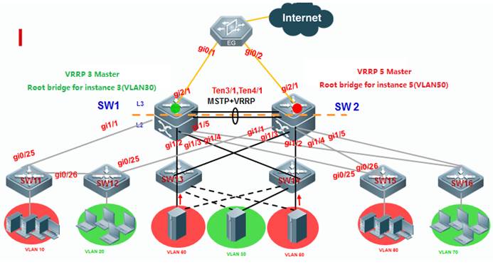
SW1 is the master VRRP gateway for users on vlan10,20,30,40,60,and 70,and backup VRRP for servers on vlan 50 and 80.SW2 is themaster VRRP gateway for servers on vlans 50 and 80 , and backup VRRP for userson vlan 10,20,30,40,60 and 70. Connect SW1 and SW2 through an Aggregate port toensure reliability and configure this AP as Trunk port.
The IP address of SW1 on VLANs from 10 to 80 are192.168.10.1 to 192.168.80.1 , and IP address of SW2 on VLANs from 10 to 80 are192.168.10.2 to 192.168.80.2 , and VRRP IP address are 192.168.10.254 to192.168.80.254.
II. ConfigurationSteps
Configuring SW1
Configuring MSTP
Ruijie#configterminal
Ruijie(config)#vlanrange 10,20,30,40,50,60,70,80
Ruijie(config-vlan-range)#exit
Ruijie(config)#spanning-treemst configuration ------>enter mst configuration mode
Ruijie(config-mst)#nameruijie ------>switches in a same MSTP area must have the sameinstance name
Ruijie(config-mst)#instance1 vlan 10,20,30,40,60,70 ----->map vlan 10,20,30,40,60,70 to instance 1 , andswitches in a same MSTP area must have the same mapping
Ruijie(config-mst)#instance2 vlan 50,80 -----> map vlan 50,80 to instance 2 , and switches in a sameMSTP area must have the same mapping
Ruijie(config-mst)#exit
Ruijie(config)#spanning-treemst 0 priority 0 ----->By default , instance 0 exists ,and any other vlansthat haven't mapped to an instance are mapped to instance 0. SW1 is the rootbridge for instance 0
Ruijie(config)#spanning-treemst 1 priority 0 ----->SW1 is the root bridge in instance 1
Ruijie(config)#spanning-treemst 2 priority 4096 ----->SW1 is the secondary bridge in instance 2
Ruijie(config)#spanning-tree ------>enableSTP feature
Configuring AP
Ruijie#configterminal
Ruijie(config)#interfaceaggregateport 1
Ruijie(config-if-AggregatePort1)#switchport mode trunk
Ruijie(config-if-AggregatePort1)#exit
Ruijie(config)#interfacetengigabitEthernet 3/1
Ruijie(config-if-TenGigabitEthernet3/1)#port-group 1
Ruijie(config-if-TenGigabitEthernet3/1)#exit
Ruijie(config)#interfacetengigabitEthernet 3/2
Ruijie(config-if-TenGigabitEthernet3/2)#port-group 1
Ruijie(config-if-TenGigabitEthernet3/2)#exit
Ruijie(config)#interfacerange gigabitEthernet 1/1-5
Ruijie(config-if-range)#switchportmode trunk ----->don't forget to prune trunk port
Configuring VRRP
Ruijie(config)#vlan10
Ruijie(config)#intervlan 10
Ruijie(config-if-VLAN10)#ip address 192.168.10.1 255.255.255.0
Ruijie(config-if-VLAN10)#vrrp 10 ip 192.168.10.254
Ruijie(config-if-VLAN10)#vrrp 10 priority 120 ------>vrrp group id=10 , priority value=120(the bigger the number , the more likely the switch will be chosen as the master ,and default value is 100)
Ruijie(config-if-VLAN10)#exit
Ruijie(config)#vlan20
Ruijie(config)#intervlan 20
Ruijie(config-if-VLAN20)#ip address 192.168.20.1 255.255.255.0
Ruijie(config-if-VLAN20)#vrrp 20 ip 192.168.20.254
Ruijie(config-if-VLAN20)#vrrp 20 priority 120
Ruijie(config-if-VLAN20)#exit
...........Configurationof VLAN 30,40,60,70 are omitted............
VRRPprimary gateway of VLAN 50,80 is SW2 which is the root bridge of instance 2
Ruijie(config)#vlan50
Ruijie(config)#intervlan 50
Ruijie(config-if-VLAN50)#ip address 192.168.50.1 255.255.255.0
Ruijie(config-if-VLAN50)#vrrp 50 ip 192.168.50.254 ------>vrrp group id=50, priority value remains default setting(the bigger the number , the morelikely the switch will be chosen as the master ,and default value is 100)
Ruijie(config-if-VLAN50)#exit
Ruijie(config)#vlan80
Ruijie(config)#intervlan 80
Ruijie(config-if-VLAN80)#ip address 192.168.80.1 255.255.255.0
Ruijie(config-if-VLAN80)#vrrp 80 ip 192.168.80.254 ------>vrrp groupid=80 , priority value remains default setting(the bigger the number , the morelikely the switch will be chosen as the master ,and default value is 100)
Ruijie(config-if-VLAN80)#exit
Configuring SW2
Configuring MSTP
Ruijie#configterminal
Ruijie(config)#vlanrange 10,20,30,40,50,60,70,80
Ruijie(config-vlan-range)#exit
Ruijie(config)#spanning-treemst configuration ------>enter mst configuration mode
Ruijie(config-mst)#nameruijie ------>switches in a same MSTP area must have the sameinstance name
Ruijie(config-mst)#instance1 vlan 10,20,30,40,60,70 ----->map vlan 10,20,30,40,60,70 toinstance 1 , and switches in a same MSTP area must have the same mapping
Ruijie(config-mst)#instance2 vlan 50,80 ----->map vlan 50,80 to instance 2 , and switches in a sameMSTP area must have the same mapping
Ruijie(config-mst)#exit
Ruijie(config)#spanning-treemst 0 priority 4096 ----->By default , instance 0 exists ,and any other vlansthat haven't mapped to an instance are mapped to instance 0. SW2 is thesecondary root bridge in instance 0
Ruijie(config)#spanning-treemst 1 priority 4096----->SW2 is the secondary root bridge in instance 1
Ruijie(config)#spanning-treemst 2 priority 0 ----->SW2 is the root bridge in instance 2
Ruijie(config)#spanning-tree ------>enable STP feature
Configuring AP
Ruijie#configterminal
Ruijie(config)#interfaceaggregateport 1
Ruijie(config-if-AggregatePort1)#switchport mode trunk
Ruijie(config-if-AggregatePort1)#exit
Ruijie(config)#interfacetengigabitEthernet 3/1
Ruijie(config-if-TenGigabitEthernet3/1)#port-group 1
Ruijie(config-if-TenGigabitEthernet3/1)#exit
Ruijie(config)#interfacetengigabitEthernet 3/2
Ruijie(config-if-TenGigabitEthernet3/2)#port-group 1
Ruijie(config-if-TenGigabitEthernet3/2)#exit
Ruijie(config)#interfacerange gigabitEthernet 1/1-5
Ruijie(config-if-range)#switchportmode trunk ----->don't forget to prune trunk port
Configuring VRRP
VRRP backup gateway of VLAN10,20,30,40,60,70 is SW2 which is the backup bridge of instance 1
Ruijie(config)#vlan10
Ruijie(config)#intervlan 10
Ruijie(config-if-VLAN10)#ip address 192.168.10.2 255.255.255.0
Ruijie(config-if-VLAN10)#vrrp 10 ip 192.168.10.254 ------>vrrp groupid=10 , priority value remains default setting(the bigger the number , the morelikely the switch will be chosen as the master ,and default value is 100) .
Ruijie(config-if-VLAN10)#exit
Ruijie(config)#vlan20
Ruijie(config)#intervlan 20
Ruijie(config-if-VLAN20)#ip address 192.168.20.2 255.255.255.0
Ruijie(config-if-VLAN20)#vrrp 20 ip 192.168.20.254 ------>vrrp group id=20, priority value remains default setting(the bigger the number , the morelikely the switch will be chosen as the master ,and default value is 100) .
Ruijie(config-if-VLAN20)#exit
...........Configurationof VLAN 30,40,60,70 are omitted............
Ruijie(config)#vlan50
Ruijie(config)#intervlan 50
Ruijie(config-if-VLAN50)#ip address 192.168.50.2 255.255.255.0
Ruijie(config-if-VLAN50)#vrrp 50 ip 192.168.50.254
Ruijie(config-if-VLAN50)#vrrp 50 priority 120 ------>vrrp group id=50 , priority value=120(the bigger the number , the more likely the switch will be chosen as the master ,and default value is 100)
Ruijie(config-if-VLAN50)#exit
Ruijie(config)#vlan80
Ruijie(config)#intervlan 80
Ruijie(config-if-VLAN80)#ip address 192.168.80.2 255.255.255.0
Ruijie(config-if-VLAN80)#vrrp 80 ip 192.168.80.254
Ruijie(config-if-VLAN80)#vrrp 80 priority 120 ------>vrrp group id=80, priority value =120(the bigger the number , the more likely the switch willbe chosen as the master ,and default value is 100)
Ruijie(config-if-VLAN80)#exit
Configuring SW11,SW12,S13,S14,S15,S16 :
Ruijie#configterminal
Ruijie(config)#interfacerange gigabitEthernet 0/25-26
Ruijie(config-if-range)#switchportmode trunk
Ruijie(config-if-range)#exit
Ruijie(config)#vlanrange 10,20,30,40,50,60,70,80
Ruijie(config-vlan-range)#exit
Ruijie(config)#spanning-treemst configuration
Ruijie(config-mst)#nameruijie
Ruijie(config-mst)#instance1 vlan 10,20,30,40,60,70
Ruijie(config-mst)#instance2 vlan 50,80
Ruijie(config-mst)#exit
Ruijie(config)#spanning-tree
Connectting cables and verifying status ofMSTP and VRRP
1. This example displays that SW1 is theroot bridge in instance 0 and 1, and SW2 is the root bridge in instance 2.
SW1:
RuijieSW1#showspanning-tree summary
Spanningtree enabled protocol mstp
MST0 vlans map : 1-9, 11-19, 21-29, 31-39, 41-49, 51-59, 61-69, 71-79, 81-4094
Root ID Priority 0
Address 1414.4b5a.198c ------> MAC address of Root bridge in instance0
this bridge is root
Hello Time 2 sec Forward Delay 15 sec Max Age 20 sec
Bridge ID Priority 0
Address 1414.4b5a.198c ------>local MAC address
Hello Time 2 sec Forward Delay 15 sec Max Age 20 sec
Interface Role Sts Cost Prio OperEdge Type
-------------------- --- ---------- -------- -------- ----------------
Ag1 Desg FWD 19000 128 False P2p
Gi0/1 Desg FWD 20000 128 False P2p
MST1 vlans map : 10, 20, 30, 40, 60, 70
Region Root Priority 0
Address 1414.4b5a.198c ------>MAC address of Root bridge in instance 1
this bridge is region root
Bridge ID Priority 0
Address 1414.4b5a.198c ------>local MAC address
Interface Role Sts Cost Prio OperEdge Type
-------------------- --- ---------- -------- -------- ----------------
Ag1 Desg FWD 19000 128 False P2p
Gi0/1 Desg FWD 20000 128 False P2p
MST2 vlans map : 50, 80
Region Root Priority 0
Address 1414.4b5a.18d4 ------>MAC address of Root bridge ininstance 2
this bridge is region root
Bridge ID Priority 4096
Address 1414.4b5a.198c
Interface Role Sts Cost Prio OperEdge Type
-------------------- --- ---------- -------- -------- ----------------
Ag1 Root FWD 19000 128 False P2p
Gi0/1 Desg FWD 20000 128 False P2p
SW2:
Ruijie#showspanning-tree summary
Spanningtree enabled protocol mstp
MST0 vlans map : 1-9, 11-19, 21-29, 31-39, 41-49, 51-59, 61-69, 71-79, 81-4094
Root ID Priority 0
Address 1414.4b5a.198c ------>MAC address of Root bridge which isSW1 in instance 0
this bridge is root
Hello Time 2 sec Forward Delay 15 sec Max Age 20 sec
Bridge ID Priority 4096
Address 1414.4b5a.18d4 ------>local MAC address
Hello Time 2 sec Forward Delay 15 sec Max Age 20 sec
Interface Role Sts Cost Prio OperEdge Type
-------------------- --- ---------- -------- -------- ----------------
Ag1 Root FWD 19000 128 False P2p
Gi2/0/1 Desg FWD 20000 128 False P2p
MST1 vlans map : 10, 20, 30, 40, 60, 70
Region Root Priority 0
Address 1414.4b5a.198c ------>MAC address of Root bridge in instance 1
this bridge is region root
Bridge ID Priority 4096
Address 1414.4b5a.18d4 ------>local MAC address
Interface Role Sts Cost Prio OperEdge Type
-------------------- --- ---------- -------- -------- ----------------
Ag1 Root FWD 19000 128 False P2p
Gi2/0/1 Desg FWD 20000 128 False P2p
MST2 vlans map : 50, 80
Region Root Priority 0
Address 1414.4b5a.18d4 ------>MAC address of Root bridge ininstance 2
this bridge is region root
Bridge ID Priority 0
Address 1414.4b5a.18d4 ------>local MAC address
Interface Role Sts Cost Prio OperEdge Type
-------------------- --- ---------- -------- -------- ----------------
Ag1 Desg FWD 19000 128 False P2p
Gi2/0/1 Desg FWD 20000 128 False P2p
2. This example displays that SW1 is themaster on vlan 10,20,30,40,60 and 70 , and the backup on vlan 50 and 80. SW2 isthe master on vlan 50 and 80, and the backup on vlan 10,20,30,40,60 and 70.
SW1:
Ruijie#showvrrp brief
Interface Grp Pri timer Own Pre State Master addr Group addr
VLAN10 10 120 3.53 - P Master 192.168.10.1 192.168.10.254
VLAN20 20 120 3.53 - P Master 192.168.20.1 192.168.20.254
VLAN30 30 120 3.53 - P Master 192.168.30.1 192.168.30.254
VLAN40 40 120 3.53 - P Master 192.168.40.1 192.168.40.254
VLAN50 50 100 3.60 - P Backup 192.168.50.2 192.168.50.254
VLAN60 60 120 3.53 - P Master 192.168.60.1 192.168.60.254
VLAN70 70 120 3.53 - P Master 192.168.70.1 192.168.70.254
VLAN80 80 100 3.60 - P Backup 192.168.80.2 192.168.80.254
SW2:
RuijieSW2#showvrrp brief
Interface Grp Pri timer Own Pre State Master addr Group addr
VLAN10 10 100 3.60 - P Backup 192.168.10.1 192.168.10.254
VLAN20 20 100 3.60 - P Backup 192.168.20.1 192.168.20.254
VLAN30 30 100 3.60 - P Backup 192.168.30.1 192.168.30.254
VLAN40 40 100 3.60 - P Backup 192.168.40.1 192.168.40.254
VLAN50 50 120 3.53 - P Master 192.168.50.2 192.168.50.254
VLAN60 60 100 3.60 - P Backup 192.168.60.1 192.168.60.254
VLAN70 70 100 3.60 - P Backup 192.168.70.1 192.168.70.254
VLAN80 80 120 3.53 - P Master 192.168.80.2 192.168.80.254
3. This exmaple displays how to verify rootbridge on access switches and whether MSTP has blocked some ports to prevent aloop.
Ruijie#showspanning-tree summary
Spanningtree enabled protocol mstp
MST0 vlans map : 1-9, 11-19, 21-29, 31-39, 41-49, 51-59, 61-69, 71-79, 81-4094
Root ID Priority 0
Address 1414.4b5a.198c
this bridge is root
Hello Time 2 sec Forward Delay 15 sec Max Age 20 sec
Bridge ID Priority 32768
Address 001a.a9c4.05f2
Hello Time 2 sec Forward Delay 15 sec Max Age 20 sec
Interface Role Sts Cost Prio Type OperEdge
-------------------- --- ---------- -------- ----- ---------------
Gi0/24 Altn BLK 20000 128 P2p False ------>one Blocked port
Gi0/23 Root FWD 20000 128 P2p False ------>one Root port
MST1 vlans map : 10, 20, 30, 40, 60, 70
Region Root Priority 0
Address 1414.4b5a.198c ------>MAC address of Root bridge which is SW1 ininstance 1
this bridge is region root
Bridge ID Priority 32768
Address 001a.a9c4.05f2
Interface Role Sts Cost Prio Type OperEdge
-------------------- --- ---------- -------- ----- ---------------
Gi0/24 Altn BLK 20000 128 P2p False ------>one Blocked port
Gi0/23 Root FWD 20000 128 P2p False ------>one Root port
MST2 vlans map : 50, 80
RegionRoot Priority 0
Address 1414.4b5a.18d4 ------>MAC address of Root bridgewhich is SW2 in instance 2
this bridge is region root
Bridge ID Priority 32768
Address 001a.a9c4.05f2
Interface Role Sts Cost Prio Type OperEdge
-------------------- --- ---------- -------- ----- ---------------
Gi0/24 Root FWD 20000 128 P2p False ------>one Blocked port
Gi0/23 Altn BLK 20000 128 P2p False ------>one Root port
When you connect Ruijie switch toother vendors, pay attention to spanning-tree compatibility:
1. When youconnect Ruijie to Cisco, you must double confirm whether Cisco firmwaresupports standard MSTP. So far, Cisco switch with firmware 12.25(SE) and abovesupports standard MSTP , but any other older firmware doesn't ,so the oldfirmware that runs nonstandard MSTP has capatibility issue .So you must upgradeswitch to version 12.25(SE) and above.If Cisco switch is too old to upgrade toversion 12.25(SE) and above, you can disable STP and enable BPDU bridge mode tobypass all bpdu packets.To enable BPDU bridge mode, perform this task:
Ruijie(config)#no spanning-tree
Ruijie(config)#bridge-frameforwarding protocol bpdu
2. We suggest you to configure completelythe same MSTP name , revision , instance mapping when you enable MSTP on Ruijieand other vendors switch to prevent STP compatibility issue. You can alsoenable RSTP because RSTP has better compatibility.
2.8.3.4 Configuring Spanningtree optimization
I. Network Topology
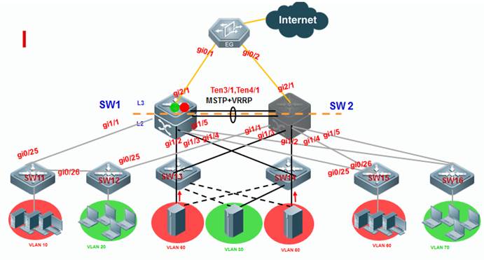
2.8.3.5 Verifying MSTP+VRRP
I. Network Topology
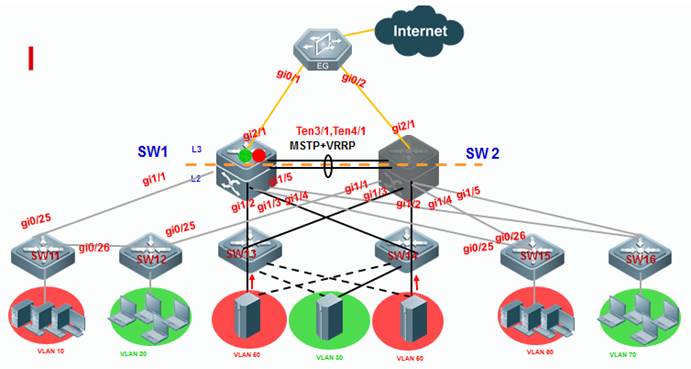
2.8.4 ARPSpoofing Protection
Overview
ARP(Address ResolutionProtocol) provides IP communication within a Layer 2 broadcast domain bymapping an IP address to a MAC address. For example, host B wants to sendinformation to host A but does not have the MAC address of host A in its ARPcache. In ARP terms, host B is the sender and host A is the target.
To get the MAC address of host A, host B generates abroadcast message for all hosts within the broadcast domain to obtain the MACaddress associated with the IP address of host A. All hosts within thebroadcast domain receive the ARP request, and host A responds with its MACaddress.
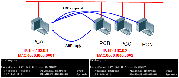
Feature
ARP itself does not check the validity of incoming ARPpackets, a drawback of ARP. In this way, attackers can launch ARP spoofingattacks easily by exploiting the drawback of the protocol. The most typical oneis the man in the middle attack, which is described as follows:
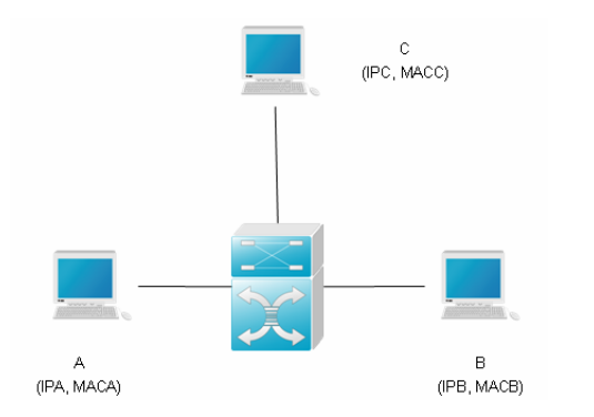
As shown in the diagram, devices A, B and C areconnected to Ruijie device and located in the same subnet. Their IP and MACaddresses are respectively represented by (IPA, MACA), (IPB, MACB) and (IPC,MACC). When device A needs to communicate with device B in the network layer,device A broadcasts an ARP request in the subnet to query the MAC value ofdevice B. Upon receiving this ARP request packet, device B updates its ARPbuffer using IPA and MACA, and sends an ARP response. Upon receiving thisresponse, device A updates its ARP buffer using IPB and MACB.
With this model, device C will cause the correspondingrelationship of ARP entries in device A and device B incorrect. The policy isto broadcast ARP response to the network continuously. The IP address in thisresponse is IPA/IPB, and the MAC address is MACC. Then, ARP entries (IPB andMACC) will exist in device A, and ARP entries (IPA and MACC) exist in device B.Communication between device A and device B is changed to communication withdevice C, which is unknown to devices A and B. Device C acts as an intermediaryand it just modifies the received packets appropriately and forwards to anotherdevice. This is the well-known man in the middle attack.
2.8.4.1 Scenario of static IPaddress assignment
Scenario
Port IP&MAC binding + ARP-check:In a network without 802.1x authentication, you canmanually bind IP&MAC address of users to a security entry on each port on aswitch and enable ARP-check feature globablly to prevent ARP spoofing.Users connectedto a switch port can pass through the port verification and have access tonetwork only when IP&MAC address of the users are totally the same to thesecurity entry on the port.
Merit: This is a very strict method to control allusers in your network and switches verify each ARP packet in hardware withoutconsuming CPU resource
Demerit: You must collectIP&MAC address of each users and the port numbers to which every usersconnect on each switch, so this method cost you plenty of time tocollect information and configure switches and it is also not flexible if usersmove their physical location very often.
I. Requirements
Administrator assign IP address to users manually, andconfigure "port-security + ARP-check" method on switches to defendagainst ARP spoofing.
II. Network Topology
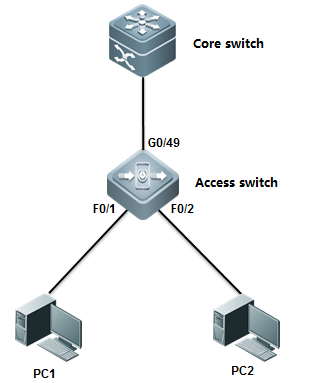
III. ConfigurationTips
1. You must enable port-security on portconnected to users, not uplink port
2. You must enable ARP-check on portconnected to users, not uplink port
IV. ConfigurationSteps
Configuring core switch:
Assign IP address to vlan 10 which is usergateway
Ruijie(config)#interfacevlan 10
Ruijie(config-if-VLAN10)#ip address 192.168.1.254 255.255.255.0
Ruijie(config-if-VLAN10)#end
Ruijie#wr
Configuring access switch:
Ruijie>enable
Ruijie#configureterminal
Ruijie(config)#interfacefastEthernet 0/1
Ruijie(config-if-FastEthernet0/1)#switchport port-security binding 0021.CCCF.6F70 vlan 10 192.168.1.1
------> bind static IP address 192.168.1.1 and MAC address0021.CCCF.6F70 on VLAN 10 to security entry on F0/1
Ruijie(config-if-FastEthernet0/1)#switchport port-security ------>enable port-security
Ruijie(config-if-FastEthernet0/1)#arp-check ------>enablearp-check
Ruijie(config-if-FastEthernet0/1)#exit
Ruijie(config)#interfacfastEthernet 0/2
Ruijie(config-if-FastEthernet0/2)# switchport port-security binding 0023.5abd.1975 vlan 10 192.168.1.2
------>bind static IP address 192.168.1.2 and MAC address0023.5abd.1975 on VLAN 10 to security entry on F0/2
Ruijie(config-if-FastEthernet0/2)#switchport port-security ------>enable port-security
Ruijie(config-if-FastEthernet0/2)#arp-check ------>enablearp-check
Ruijie#write
Ruijie(config)#interfacfastEthernet 0/3
Ruijie(config-if-FastEthernet0/3)# switchport port-security binding 192.168.1.3
------>you can also bind onlly static IP address 192.168.1.3to security entry on F0/3 in order to be more flexible but lower security
Ruijie(config-if-FastEthernet0/3)#switchport port-security
Ruijie(config-if-FastEthernet0/3)#arp-check
Ruijie#write
V.Verification
1) How to display security entry on eachport
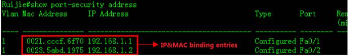
2) How to display status of ARP-check
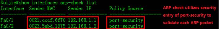
Scenario
Global IP&MAC binding+ ARP-check:In a network without 802.1x authentication, you canmanually bind IP&MAC address of users to global security table on a switchand enable ARP-check feature globablly to prevent ARP spoofing.Users connectedto a switch port can pass through the global verification and have access tonetwork only when IP&MAC address of the users are totally the same to theglobal security table on the switch
Merit: This is a less strict method to control allusers in your network than solution 1, and switches verify each ARP packet inhardware without consuming CPU resource
Demerit: You must collect IP&MAC address of eachusers on each switch, so this method cost you plenty of time to collectinformation and configure switches.
I. Requirements
Administrator assign static IP address to users, andconfigures "port-security + ARP-check" method on switches to preventARP spoofing
II. Network Topology
III. ConfigurationTips
1. Bind IP&MAC address of users to global securitytable
2. Configure uplink port as trusted port on which allpackets can pass through without validation
3. Enable address-bind feature globally
4. Enable arp-check feature globally
IV. ConfigurationSteps
Configuring core switch:
Manually assign IP address to Vlan 10 whichis user gateway
Ruijie(config)#interfacevlan 10
Ruijie(config-if-VLAN10)#ip address 192.168.1.254 255.255.255.0
Ruijie(config-if-VLAN10)#end
Ruijie#wr
Configuring access switch:
Ruijie>enable
Ruijie#configureterminal
Ruijie(config)#address-bind192.168.1.1 0021.cccf.6f70 ------>bind IP 192.168.1.1 and MAC address 0021.cccf.6f70 toglobal security table
Ruijie(config)#address-bind192.168.1.2 0023.5abd.1975 ------>bind IP 192.168.1.2 and MAC address 0023.5abd.1975 toglobal security table
Ruijie(config)#address-binduplink gigabitEthernet 0/25 ------>configure uplink port G0/25 astrusted port on which all packets can pass through without validation
Ruijie(config)#address-bindinstall ------>enable address-bind
Ruijie(config)#interfacerange fastEthernet 0/1-2
Ruijie(config-if-range)#arp-check------>enablearp-check
Ruijie(config-if-range)#end
Ruijie#write
Note:
If users want to use IPv6 address to visitnetwork, you must enable IPv6 capatible mode on switch that have address-bindenabled. Perform this task:
Ruijie(config)#address-bindipv6-mode ?
compatible IPV6 compatible mode ------>campatible mode ,allow bindingusers to visit network via IPv6 address
loose IPV6 loose mode ------>loose mode ,allow all IPv6 users to visit network unlimitedly
strict IPV6 strict mode (default: strict)------>strict mode ,even binding users can't visit network via IPv6 address, this is the defaultmode
Ruijie(config)#address-bindipv6-mode compatible
V.Verification
1. How to display global security table
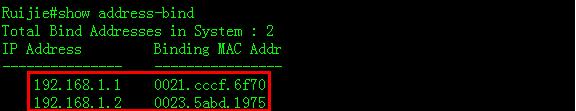
2. How to display trusted port
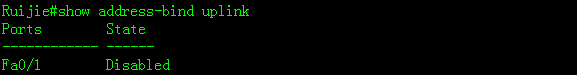
3. How to verify ARP-check table
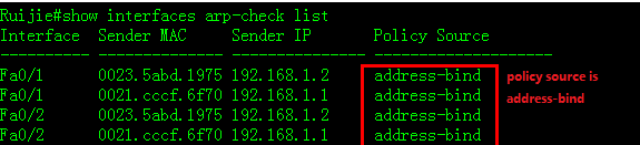
Scenario
802.1X authentication+ ARP-check:In a network that have 802.1x authenticationenabled,users must be running 802.1X-compliant client software ,such as Ruijiesupplicant SU and SA . Switch collects IP&MAC address when communicateswith 802.1X-compliant client software and write these information into global securitytable.ARP-check validate each users based on thie global security table toprevent ARP spoofing.
Merit: This is the simplest method for you to configureswitch and maintenance
Demerit : You must build your network with Ruijie802.1X-compliant client software SU/SA and a Radius Server (for example ,RuijieSAM),and it consumes more hardware resourcebecause it costs switch one more security entry in hardware when a user passthe authentication .
I. Requirements
Administrator assigns static IP address to user andenable 802.1x authentication through the overall network with Ruijie SU/SA andSAM to prevent ARP spoofing.
II. Network Topology
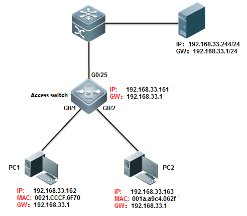
III. ConfigurationTips
1. Enable basic dot1x authenticationfunction on access switch
2. Modify authorization mode to"supplicant mode"
3. Enable arp-check on port connected tousers
IV. ConfigurationSteps
Configuring access switch
1) Configure dot1x authentication on switch
For complete information about 802.1xconfiguration ,see switch configuration guide , such as 《RG-S8600E Series Switches RGOS Configuration Guide》
2) Configure authorization mode in"supplicant mode"
Ruijie(config)#aaaauthorization ip-auth-mode supplicant
Note: Ifusers want to use IPv6 address to visit network, you must enable IPv6 capatiblemode on switch that have address-bind enabled. Perform this task:
Ruijie(config)#address-bindipv6-mode ?
compatible IPV6 compatible mode ------>campatible mode ,allow bindingusers to visit network via IPv6 address
loose IPV6 loose mode ------>loose mode ,allow all IPv6 users to visit network unlimitedly
strict IPV6 strict mode (default: strict)------>strict mode ,even binding users can't visit network via IPv6 address, this is the defaultmode
Ruijie(config)#address-bindipv6-mode compatible
3) Enable arp-check
Ruijie(config)#interfacerange g0/1-2
Ruijie(config-if-range)#arp-check
Ruijie(config-if-range)#end
Ruijie#write
V.Verification
Ruijie(config)#showinterfaces gigabitEthernet 0/1 arp-check list
2.8.4.2 Scenarioof dynamic IP address assignment(DHCP)
Scenario
DHCP Snooping with ARP-check:This solution can prevents ARP spoofing inthe network in which DHCP server assign IP address to users .You can alsoenable 802.1x authentication or web authentication or you can disable anyauthentications in your network.
Merit: Very simple configuration and easy maintenance.
Demerit: DHCP snooping and ARP-check are enforced inhardware , so this method is is not applied if there are insufficient hardwareresources available on switch.How many users the switch can carry depend on itsspecification.
When switch hardware recources are insufficient , systemreturns the following syslog :
%SECURITY-3-TCAM_RESOURCE_LIMIT: TCAM resource istemporary not available.
I. Requirements
DHCP server assigns IP address to users ,andadministrator uses "DHCP Snooping with ARP-check" to prevent ARPspoofing.
II. Network Topology
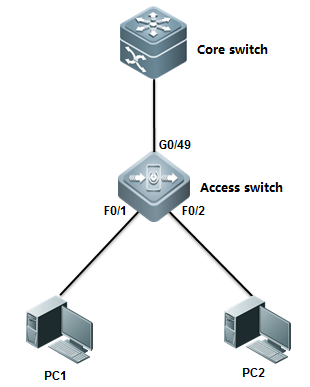
III. ConfigurationTips
1. Core switch acts as DHCP server
2. Enable DHCP Snooping on access switch and configureuplink port as DHCP Snooping trusted port.
3. Enable ARP-check on ports connected touser
IV. ConfigurationSteps
Configuring core switch:
1. Enable DHCP service
Ruijie(config)#servicedhcp
2. Manually Assign IP address to vlan 1which is user gateway
Ruijie(config)#interfacevlan 1
Ruijie(config-if-VLAN1)#ip address 192.168.1.254 255.255.255.0
Ruijie(config-if-VLAN1)#exit
3. Create DHCP IP address pool
Ruijie(config)#ipdhcp pool vlan1
Ruijie(dhcp-config)#network192.168.1.0 255.255.255.0 ------>network subnet
Ruijie(dhcp-config)#dns-server218.85.157.99 ------>DNS Server
Ruijie(dhcp-config)#default-router192.168.1.254 ------>specify user gateway
Ruijie(dhcp-config)#end
Ruijie#wr
Configuring access switch:
1. Enable DHCP Snooping
Ruijie>enable
Ruijie#configureterminal
Ruijie(config)#ipdhcp snooping
2. Configure the port connected to DHCP server as DHCPSnooping trusted port.
Ruijie(config)#interfacegigabitEthernet 0/49
Ruijie(config-GigabitEthernet0/49)#ip dhcp snooping trust ------>By default , all ports are DHCPSnooping untrusted port. Only trusted port can forward DHCP Offer and Ackpackets
Note:
If users want to use IPv6 address to visitnetwork, you must enable IPv6 capatible mode on switch that have address-bindenabled. Perform this task
Ruijie(config)#address-bindipv6-mode ?
compatible IPV6 compatible mode ------>campatible mode ,allow bindingusers to visit network via IPv6 address
loose IPV6 loose mode ------>loose mode ,allow all IPv6 users to visit network unlimitedly
strict IPV6 strict mode (default: strict)------>strict mode ,even binding users can't visit network via IPv6 address, this is the defaultmode
Ruijie(config)#address-bindipv6-mode compatible
3. Enable arp-check
Ruijie(config)#interfacerange fastEthernet 0/1-2
Ruijie(config-if-range)#arp-check
V.Verification
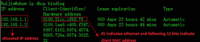
2. How to display NIC information on astation, click " Start -> Run -> cmd -> ipconfig/all "
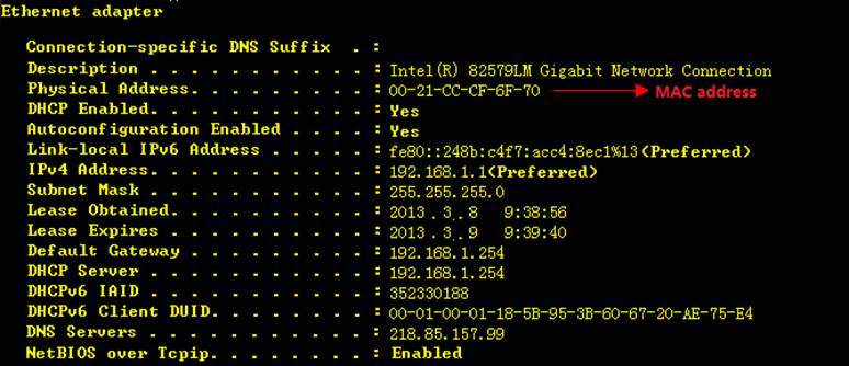
3. How to display DHCP snooping table on aaccess switch
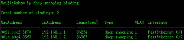
4. How to display ARP-Check table
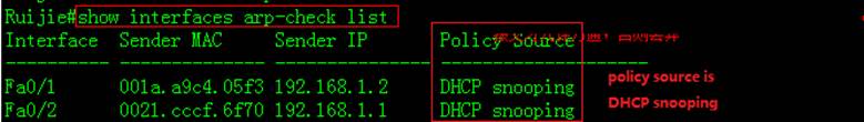
Scenario
DHCP Snooping with DAI(Dynamic ARPinspection): This solutioncan prevents ARP spoofing in the network in which DHCP server assign IP addressto users .You can also enable 802.1x authentication or web authentication oryou can disable any authentications in your network.
Merit: Very simple configuration and easy maintenance.DAI is enfored in CPU, but ARP-check is enforced in hardware.
Demerit: When a access switch carries more than 50users, we recommend you to use solution 1 in case CPU resources isinsufficient.
I. Requirements
DHCP server assigns IP address to users ,andadministrator uses "DHCP Snooping with DAI" to prevent ARP spoofing.
II. Network Topology
III. ConfigurationTips
1. Core switch acts as DHCP server
2. Enable DHCP Snooping on access switch and configureuplink port as DHCP Snooping trusted port.
3. Enable DAI on access switch and configure uplinkport as DAI trusted port.
4. Fine tune CPP and NFPP parameters andprune trunk port
IV. ConfigurationSteps
Configuring core switch:
1. Enable DHCP service
Ruijie(config)#servicedhcp
2. Manually Assign IP address to vlan 1which is user gateway
Ruijie(config)#interfacevlan 1
Ruijie(config-if-VLAN1)#ip address 192.168.1.254 255.255.255.0
Ruijie(config-if-VLAN1)#exit
3. Create DHCP IP address pool
Ruijie(config)#ipdhcp pool vlan1
Ruijie(dhcp-config)#network192.168.1.0 255.255.255.0 ------>network segment
Ruijie(dhcp-config)#dns-server218.85.157.99 ------>DNS server
Ruijie(dhcp-config)#default-router192.168.1.254 ------>specify user gateway
Ruijie(dhcp-config)#end
Ruijie#wr
Configuring access switch:
1. Enable DHCP Snooping
Ruijie>enable
Ruijie#configureterminal
Ruijie(config)#ipdhcp snooping
2. Configure the port connected to DHCP server as DHCPSnooping trusted port
Ruijie(config)#interfacegigabitEthernet 0/49
Ruijie(config-GigabitEthernet0/49)#ip dhcp snooping trust ------>By default , all ports are DHCPsnooping untrust ports. Only trusted port can forward DHCP Offer and Ackpackets
3. Enable DAI in VLAN 1
Ruijie(config)#iparp inspection vlan 1 ------>DAI inspectsVLAN 1
4 . Configure the uplink port as DAI trusted port
Ruijie(config)#intgigabitEthernet 0/25
Ruijie(config-if-GigabitEthernet0/25)#ip arp inspection trust
Configuring DAI optimization(Mandatory)
When DAI is enabled, switch forwards all ARPpackets to CPU to validate, and you must configure the following optimization.
1. Prune trunk port on uplink port on accessswitch
This example shows how to prune trunk portG0/25 and this port can carry traffic for VLAN 1 and VLAN 9 only:
Ruijie(config-if-GigabitEthernet0/25)#switchport trunk allowed vlan remove 2-8,10-4094
For complete information, see Initialization --->Configuring a Layer 2 Port --->Access or Trunk port
2. Disable NFPP on the uplink port on accessswitch, otherwise if the number of ARP packets sent from Core switch to accessswitch exceeds the default NFPP rate-limit threshold, NFPP will drop theexceeding arp packets which would be users'
Ruijie(config)#intg0/25
Ruijie(config-if-GigabitEthernet0/25)#no nfpp arp-guard enable
Ruijie(config-if-GigabitEthernet0/25)#no nfpp dhcp-guard enable
Ruijie(config-if-GigabitEthernet0/25)#no nfpp dhcpv6-guard enable
Ruijie(config-if-GigabitEthernet0/25)#no nfpp icmp-guard enable
Ruijie(config-if-GigabitEthernet0/25)#no nfpp ip-guard enable
Ruijie(config-if-GigabitEthernet0/25)#no nfpp nd-guard enable
Ruijie(config-if-GigabitEthernet0/25)#exit
Ruijie(config)#
3. Increase CPP arp rate-limit threshold to500PPS (180PPS by default) in case that CPP drops the exceeding packets.
Ruijie(config)#cpu-protecttype arp pps 500
V.Verification
1. How to display DAI status
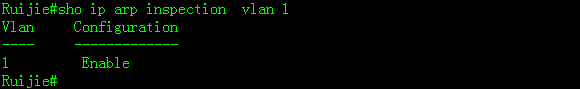
2. How to display DHCP Snooping bindingtable
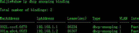
Scenario
802.1X authentication with ARP-check:In a network that have 802.1x authenticationenabled,users must be running 802.1X-compliant client software ,such as Ruijiesupplicant SU and SA and DHCP server assigns IP address to users beforeauthentication.
Merit:This is the simplestmethod for you to configure switch and maintenance
Demerit : You must build your network with Ruijie802.1X-compliant client software SU/SA and a Radius Server (for example ,RuijieSAM),and it consumes more hardware resourcebecause it costs switch one more security entry in hardware when a user passthe authentication .In addition , you must configure a global security tunnelto bypass DHCP packets because users must acquire IP address before 802.1Xauthentication
I. Requirements
DHCP Server assigns IP address to users ,thenadministrator uses "802.1X authentication+ ARP-check" to prevent ARPspoofing.
II. Network Topology
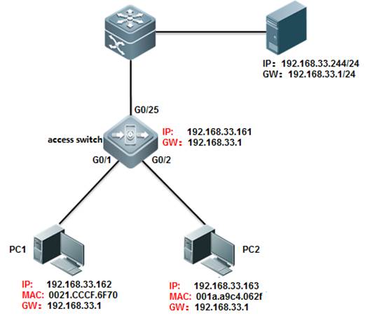
III. ConfigurationTips
1. Enable basic dot1x authentication onaccess switch
2. Configure a global security tunnel tobypass DHCP packets
3. Modify authorization mode to"supplicant mode"
4. Enable arp-check on port connected tousers
IV. ConfigurationSteps
Configuring access switch
1. Configure dot1x authentication on switch
For complete information about 802.1x configuration,see switch configuration guide , such as 《RG-S8600ESeries Switches RGOS Configuration Guide》
2. Configure a global security tunnel tobypass DHCP packets
Ruijie(config)#expertaccess-list extended dhcp
Ruijie(config-exp-nacl)#permitudp any any any any eq bootps ------>bypass DHCP packets
Ruijie(config-exp-nacl)#
Ruijie(config)#securityglobal access-group dhcp
3. Modify authorization mode to"supplicant mode"
Ruijie(config)#aaaauthorization ip-auth-mode supplicant
Note:
If users want to use IPv6 address to visitnetwork, you must enable IPv6 capatible mode on switch that have address-bind enabled.Perform this task:
Ruijie(config)#address-bindipv6-mode ?
compatible IPV6 compatible mode ------>campatible mode ,allow bindingusers to visit network via IPv6 address
loose IPV6 loose mode ------>loose mode ,allow all IPv6 users to visit network unlimitedly
strict IPV6 strict mode (default: strict)------>strict mode ,even binding users can't visit network via IPv6 address, this is the defaultmode
Ruijie(config)#address-bindipv6-mode compatible
4. Enable arp-check
Ruijie(config)#interfacerange g0/1-2
Ruijie(config-if-range)#arp-check
Ruijie(config-if-range)#end
Ruijie#write
V.Verification
Ruijie(config)#showinterfaces gigabitEthernet 0/1 arp-check list
2.8.5 VSD
Scenario
As the data center network expands, the service type isvaried, and network management becomes more complicated, higher requirementsare raised on service isolation, safety, and reliability of the network. Withthe rapid development of hardware and maturity of the multi-frame, clustered,and distributed routing and switching system, the service processing capabilityof a single physical network device has reached a new level. It is urgent tomake full use of the powerful service processing capability of a singlephysical device, adapt to the current service requirements, and realize smoothevolution of future expansion. Network device virtualization is a perfectmethod. It provides an easier virtualization means for network users. It is notlimited to specific services or channels but serves to provide virtualizationof the entire device.
Function Overview
The Virtual Switch Device (VSD) is a network systemvirtualization technology which divides a physical device into multiple logicaldevices. Each logical device is called a VSD. Each VSD has independent hardwareand software resources, including independent interface resources, CPUresources, independently-maintained routing table and forwarding table, and itsown administrator and configuration file. For users, each VSD is an independentdevice.
By VSDx technology, a physical device can bevirtualized to multiple logical devices, as shown in the following figure. Aphysical device can carry multiple network nodes in the logical topology tomaximize utilization of available resources and reduce network operation costs.Different VSs can be deployed with different services to isolate services fromfailures, improving safety and reliability of the network.
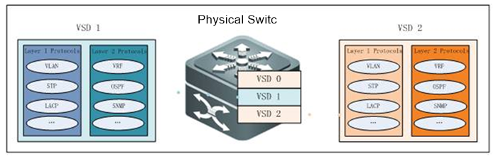
VSD Management
Out-of-band management is management through the mgmtinterface. Inband management is management through an Ethernet physicalinterface.
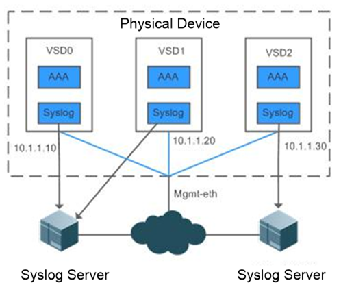
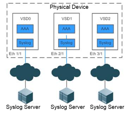
I. Requirements
To carry multiple users on a network device, isolatemanagement, simplify operation and maintenance, and isolate services, a networkdevice with good performance is virtualized to multiple logical devices, makingfull use of device resources and ensuring strong scalability of the network.Services of virtual devices are managed independently of each other.
II. Network Topology
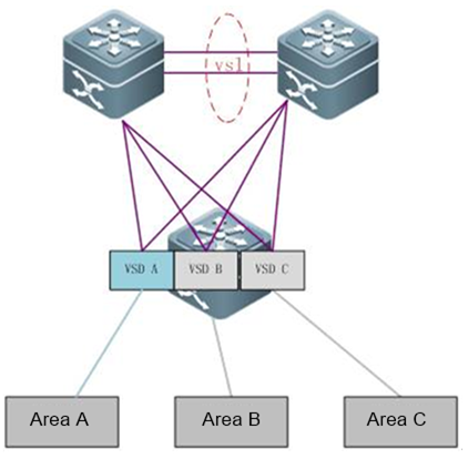
III. Configuration Tips
Install a VSD license.
Ruijie#configure terminal
Enterconfiguration commands, one per line. End with CNTL/Z.
Ruijie(config)#license install usb0:/LIC-VSD00000002328406.lic----> VSD function needlicense
Successto install license file, service name: LIC-N18000-VSD.
Create VSD A.
Ruijie#configure terminal
Enterconfiguration commands, one per line. End with CNTL/Z.
Ruijie(config)#vsd VSDA
Ruijie(config-vsd)#allocate int gi 1/1
Movingports will cause all config associated to them in source vsd to be removed. Areyou sure
tomove the ports? [yes] yes
Entireport-group is not present in the command. Missing ports will be includedautomatically
Ruijie(config-vsd)#
Create VSD B.
Ruijie#configure terminal
Enterconfiguration commands, one per line. End with CNTL/Z.
Ruijie(config)#vsd VSDB
Ruijie(config-vsd)#allocate int gi 2/1
Movingports will cause all config associated to them in source vsd to be removed. Areyou sure
tomove the ports? [yes] yes
Entireport-group is not present in the command. Missing ports will be includedautomatically
Ruijie(config-vsd)#
Create VSD C.
Ruijie#configure terminal
Enterconfiguration commands, one per line. End with CNTL/Z.
Ruijie(config)#vsd VSDC
Ruijie(config-vsd)#allocate int gi 3/1
Movingports will cause all config associated to them in source vsd to be removed. Areyou sure
tomove the ports? [yes] yes
Entireport-group is not present in the command. Missing ports will be includedautomatically
Ruijie(config-vsd)#
ManageVSDs.
ConfigureVSD functions based on actual service planning requirements. (Omitted)
IV. ConfigurationSteps
Install a VSD license.
Create VSD A.
V. Verification
View division details of line cards on the VSDinterface.
Ruijie-N18K#showvsd all
vsd_id:0
vsd_name:Ruijie
vsdmac address: 00d0.f876.9888
interface:
interface:
GigabitEthernet4/1 GigabitEthernet 4/2
GigabitEthernet4/3 GigabitEthernet 4/4
GigabitEthernet4/5 GigabitEthernet 4/6
GigabitEthernet4/7 GigabitEthernet 4/8
GigabitEthernet4/9 GigabitEthernet 4/10
GigabitEthernet4/11 GigabitEthernet 4/12
GigabitEthernet4/13 GigabitEthernet 4/14
GigabitEthernet4/15 GigabitEthernet 4/16
GigabitEthernet4/17 GigabitEthernet 4/18
GigabitEthernet4/19 GigabitEthernet 4/20
GigabitEthernet4/21 GigabitEthernet 4/22
GigabitEthernet4/23 GigabitEthernet 4/24
GigabitEthernet4/25 GigabitEthernet 4/26
GigabitEthernet4/27 GigabitEthernet 4/28
GigabitEthernet4/29 GigabitEthernet 4/30
GigabitEthernet4/31 GigabitEthernet 4/32
GigabitEthernet4/33 GigabitEthernet 4/34
GigabitEthernet4/35 GigabitEthernet 4/36
GigabitEthernet4/37 GigabitEthernet 4/38
GigabitEthernet4/39 GigabitEthernet 4/40
GigabitEthernet4/41 GigabitEthernet 4/42
GigabitEthernet4/43 GigabitEthernet 4/44
GigabitEthernet4/45 GigabitEthernet 4/46
GigabitEthernet4/47 GigabitEthernet 4/48
slot:
slot4
vsd_id:1
vsd_name:VSDA
vsdmac address: 00d0.f876.988a
interface:
GigabitEthernet1/1 GigabitEthernet 1/2
GigabitEthernet1/3 GigabitEthernet 1/4
GigabitEthernet1/5 GigabitEthernet 1/6
GigabitEthernet1/7 GigabitEthernet 1/8
GigabitEthernet1/9 GigabitEthernet 1/10
GigabitEthernet1/11 GigabitEthernet 1/12
GigabitEthernet1/13 GigabitEthernet 1/14
GigabitEthernet1/15 GigabitEthernet 1/16
GigabitEthernet1/17 GigabitEthernet 1/18
GigabitEthernet1/19 GigabitEthernet 1/20
GigabitEthernet1/21 GigabitEthernet 1/22
GigabitEthernet1/23 GigabitEthernet 1/24
GigabitEthernet1/25 GigabitEthernet 1/26
GigabitEthernet1/27 GigabitEthernet 1/28
GigabitEthernet1/29 GigabitEthernet 1/30
GigabitEthernet1/31 GigabitEthernet 1/32
GigabitEthernet1/33 GigabitEthernet 1/34
GigabitEthernet1/35 GigabitEthernet 1/36
GigabitEthernet1/37 GigabitEthernet 1/38
GigabitEthernet1/39 GigabitEthernet 1/40
GigabitEthernet1/41 GigabitEthernet 1/42
GigabitEthernet1/43 GigabitEthernet 1/44
GigabitEthernet1/45 GigabitEthernet 1/46
GigabitEthernet1/47 GigabitEthernet 1/48
slot:
slot1
vsd_id:2
vsd_name:VSDB
vsdmac address: 00d0.f876.988c
interface:
GigabitEthernet2/1 GigabitEthernet 2/2
GigabitEthernet2/3 GigabitEthernet 2/4
GigabitEthernet2/5 GigabitEthernet 2/6
GigabitEthernet2/7 GigabitEthernet 2/8
GigabitEthernet2/9 GigabitEthernet 2/10
GigabitEthernet2/11 GigabitEthernet 2/12
GigabitEthernet2/13 GigabitEthernet 2/14
GigabitEthernet2/15 GigabitEthernet 2/16
GigabitEthernet2/17 GigabitEthernet 2/18
GigabitEthernet2/19 GigabitEthernet 2/20
GigabitEthernet2/21 GigabitEthernet 2/22
GigabitEthernet2/23 GigabitEthernet 2/24
GigabitEthernet2/25 GigabitEthernet 2/26
GigabitEthernet2/27 GigabitEthernet 2/28
GigabitEthernet2/29 GigabitEthernet 2/30
GigabitEthernet2/31 GigabitEthernet 2/32
GigabitEthernet2/33 GigabitEthernet 2/34
GigabitEthernet2/35 GigabitEthernet 2/36
GigabitEthernet2/37 GigabitEthernet 2/38
GigabitEthernet2/39 GigabitEthernet 2/40
GigabitEthernet2/41 GigabitEthernet 2/42
GigabitEthernet2/43 GigabitEthernet 2/44
GigabitEthernet2/45 GigabitEthernet 2/46
GigabitEthernet2/47 GigabitEthernet 2/48
slot:
slot2
vsd_id:3
vsd_name:VSDC
vsdmac address: 00d0.f876.988d
interface:
GigabitEthernet3/1 GigabitEthernet 3/2
GigabitEthernet3/3 GigabitEthernet 3/4
GigabitEthernet3/5 GigabitEthernet 3/6
GigabitEthernet3/7 GigabitEthernet 3/8
GigabitEthernet3/9 GigabitEthernet 3/10
GigabitEthernet3/11 GigabitEthernet 3/12
GigabitEthernet3/13 GigabitEthernet 3/14
GigabitEthernet3/15 GigabitEthernet 3/16
GigabitEthernet3/17 GigabitEthernet 3/18
GigabitEthernet3/19 GigabitEthernet 3/20
GigabitEthernet3/21 GigabitEthernet 3/22
GigabitEthernet3/23 GigabitEthernet 3/24
GigabitEthernet3/25 GigabitEthernet 3/26
GigabitEthernet3/27 GigabitEthernet 3/28
GigabitEthernet3/29 GigabitEthernet 3/30
GigabitEthernet3/31 GigabitEthernet 3/32
GigabitEthernet3/33 GigabitEthernet 3/34
GigabitEthernet3/35 GigabitEthernet 3/36
GigabitEthernet3/37 GigabitEthernet 3/38
GigabitEthernet3/39 GigabitEthernet 3/40
GigabitEthernet3/41 GigabitEthernet 3/42
GigabitEthernet3/43 GigabitEthernet 3/44
GigabitEthernet3/45 GigabitEthernet 3/46
GigabitEthernet3/47 GigabitEthernet 3/48
slot:
slot3
Verify VSD login and management modes.
Ruijie#switchto vsd VSDA
***********************************************************************
RuijieGeneral Operating System Software
Copyright(c) 1998-2013s by Ruijie Networks.
AllRights Reserved.
NeitherDecompiling Nor Reverse Engineering Shall Be Allowed.
***********************************************************************
Ruijie-VSDA>enable
Ruijie-VSDA#conf
Enterconfiguration commands, one per line. End with CNTL/Z.
Ruijie-VSDA(config)#intmgmt 0
Ruijie-VSDA(config-if-Mgmt0)#ip address 10.1.1.10 255.255.255.0
Ruijie-VSDA(config-if-Mgmt0)#end
Ruijie-VSDA#switchback
Ruijie#switchto vsd VSDB
***********************************************************************
RuijieGeneral Operating System Software
Copyright(c) 1998-2013s by Ruijie Networks.
AllRights Reserved.
NeitherDecompiling Nor Reverse Engineering Shall Be Allowed.
***********************************************************************
Ruijie-VSDB>enable
Ruijie-VSDB#conf
Enterconfiguration commands, one per line. End with CNTL/Z.
Ruijie-VSDB(config)#intmgm
Ruijie-VSDB(config)#intmgmt 0
Ruijie-VSDB(config-if-Mgmt0)#ip address 10.1.1.20 255.255.255.0
Ruijie-VSDB(config-if-Mgmt0)#end
Ruijie-VSDB#switchback
Ruijie#switchto vsd VSDC
***********************************************************************
RuijieGeneral Operating System Software
Copyright(c) 1998-2013s by Ruijie Networks.
AllRights Reserved.
NeitherDecompiling Nor Reverse Engineering Shall Be Allowed.
***********************************************************************
Ruijie-VSDC>enable
Ruijie-VSDC#conf
Enterconfiguration commands, one per line. End with CNTL/Z.
Ruijie-VSDC(config)#intmgm
Ruijie-VSDC(config)#intmgmt 0
Ruijie-VSDC(config-if-Mgmt0)#ip address 10.1.1.30 255.255.255.0
Ruijie-VSDC(config-if-Mgmt0)#end
Ruijie-VSDC#switchback
2.9 Common Feature
2.9.1 Ethernet Switching
2.9.1.1 Aggregate Port
Scenario
Multiple physicallinks can be bound into a logical link, called an aggregate port (herein afterreferred to as AP).Ruijie devices provide the AP function that complies withthe IEEE802.3ad standard. This function can be used to expand link bandwidthand improve reliability. AP function supports traffic balancing that evenlyallocating the traffic toevery member link. AP function also supports linkbackup. When a link member in an AP is disconnected, the system willautomatically allocate the traffic of the member link to other active memberlinks in the AP, except for the broadcast or multicast packets it received.
Dynamic mode and Static mode
1) If you configure aggregate port mode to static on aport,the port is converted to aggregate port without negotiating.
2) If you configure aggregate port mode to dynamic withLACP (Link Aggregation Control Protocol), the port negotiates with the theother end of the link whether to be a aggregate port.
Aggregate portsconsists of three modes: Active, Passive and Static.
The port in activemode sends the LACP packets actively to the peer
The port in passivemode only responds when it receives LACP packets from the peer.
The port in staticmode is converted to aggregate port without sending any LACP packets.
The following tabledescribes the matching of different modes
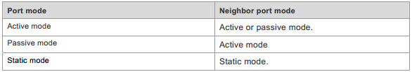
Aggregate Port Load Balancing
Traffic can be evenly distributed on the member linksof an AP according to the features such as source MAC address, destination MACaddress, combination of source MAC address and destination MAC address, sourceIP address, destination IP address, and combination of source IP address anddestination IP address.
Note:By default , the load balancing method is src-dst-mac.
This example shows how to configure load balance:
Ruijie(config)#aggregateportload-balance ?
dst-ip Destination IP address
dst-mac Destination MAC address
help Help information
mpls-label Mpls label
src-dst-ip Source and destination IP address
src-dst-ip-l4port Source and destination IP address, source and
destination L4port
src-dst-mac Source and destination MAC address
src-ip Source IP address
src-mac Source MAC address
src-port Source port
Ruijie(config)#aggregateportload-balance src-dst-ip ------>recommended
Attention:
1. You must configure the same speed,duplexand media-type on both ends of AP.You cannot put a copper port and a opticalport in the same AP.
2. You can only put L2 port in a L2 AP andL3 port in a L3 AP. You cannot change the port from L2 to L3 , or from L3 to L2after you put the ports in a AP.
3. Ruijie switch supports to put 8 ports ina AP at most
5. When you finish configuring AP , you canenter "interface aggregateport x/x" command to manage the AP.You canno longer manage the AP member independently.
Layer2 Aggregate Port (Static and Dynamic)
I. Requirements
Enable Layer 2 AP on the ports between twoCore switches to expand inter-connection bandwidth and ensure a high availablenetwork. Use src-mac load balance method.
II. Network Topology
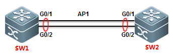
III. Configuration Tips
1. Put AP members ports in a specified AP
2. Configure AP as Trunk
3. Modify load balance method
IV. ConfigurationSteps
Static mode:
SW1:
SW1>enable
SW1#configureterminal
SW1(config)#interfacerange gigabitEthernet 0/1-2 ------>configure a range of interfaceswith the same command
SW1(config-if-range)#port-group1 ------>put G0/1 and G0/2 in AP 1 instatic mode
SW1(config-if-range)#exit
SW1(config)#interfaceaggregateport 1
SW1(config-if-AggregatePort1)#switchport mode trunk ------>configure AP 1 as Trunk
SW1(config-if-AggregatePort1)#exit
SW1(config)#aggregateportload-balance src-mac ------>modify load balance method to Src-MAC. By default, itis Src-Dst-MAC.
SW1(config)#exit
SW1#wr
SW2:
SW2>enable
SW2#configureterminal
SW2(config)#interfacerange gigabitEthernet 0/1-2
SW2(config-if-range)#port-group1
SW2(config-if-range)#exit
SW2(config)#interfaceaggregateport 1
SW2(config-if-AggregatePort1)#switchport mode trunk
SW2(config-if-AggregatePort1)#exit
SW2(config)#aggregateportload-balance src-mac
SW2(config)#exit
SW2#wr
Dynamic mode:
SW1(config)#interfacerange gigabitEthernet 0/1-2
SW1(config-if-range)#port-group1 mode active ------>put G0/1 andG0/2 in AP 1 in dynamic mode
SW1(config-if-range)#exit
SW1(config)#interfaceaggregateport 1
SW1(config-if-AggregatePort1)#switchport mode trunk ------>configure AP 1as Trunk
SW1(config-if-AggregatePort1)#exit
SW2is the same.
3. This example shows how to configure L2 APin static mode when connect Ruijie a switch to a Cisco switch
Cisco:
interfacePort-channel1
switchportmode access
interfaceFastEthernet0/1
switchportmode access
channel-group1 mode on
interfaceFastEthernet0/2
switchportmode access
channel-group1 mode on
Ruijie :
interfaceAggregatePort 1
interfaceFastEthernet 0/1
port-group1
interfaceFastEthernet 0/2
port-group1
4. This example shows how to configure L2 APin dynamic mode when connect Ruijie a switch to a Cisco switch
Cisco:
interfacePort-channel1
switchportmode access
interfaceFastEthernet0/1
switchportmode access
channel-group1 mode active
interfaceFastEthernet0/2
switchportmode access
channel-group1 mode active
Ruijie :
interfaceFastEthernet 0/1
port-group1 mode active
interfaceFastEthernet 0/2
port-group1 mode active
interfaceAggregatePort 1
V. Verification
1. How to display status of aggregate port
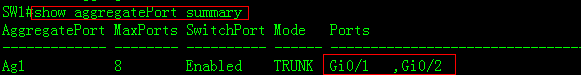
2. How to display information of AP 1
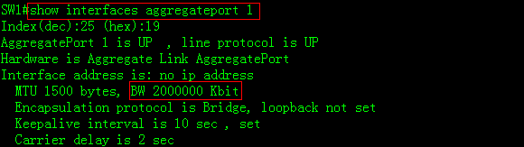
3. How to display the load balance method

Layer3 Aggregate Port (Static and Dynamic)
I. Requirements
Enable Layer 3 AP on the ports between two Coreswitches to expand inter-connection bandwidth and ensure a high availablenetwork. Use src-dst-IP load balance method.
II. Network Topology
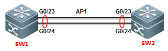
III. Configuration Tips
1. First, you must create a AP and convertit to a L3 AP, then assign a IP address to it.
2. Convert AP members to L3 ports.
3. Put the AP members in the AP
4. Modify load balance method
Note:You must follow the tips abovestep by step ,otherwise you could fail to configure L3 AP.
IV. ConfigurationSteps
SW1:
SW1>enable
SW1#configureterminal
SW1(config)#interfaceaggregateport 1
SW1(config-if-AggregatePort1)#no switchport ------>convert AP 1from L2 to L3
SW1(config-if-AggregatePort1)#ip address 1.1.1.1 255.255.255.0
SW1(config-if-AggregatePort1)#exit
SW1(config)#interfacerange gigabitEthernet 0/23-24 ------>configurea range of interfaces with the same commands
SW1(config-if-range)#noswitchport ------>convertAP members to layer 3
SW1(config-if-range)#medium-typefiber
SW1(config-if-range)#port-group1 mode active ------>put G0/23 andG0/24 in AP 1 in active mode
SW1(config-if-range)#exit
SW1(config)#aggregateportload-balance src-dst-ip ------>put G0/23 andG0/24 in AP 1 in active mode
------------------------------------------------------------------------------------------
or
SW1(config-if-range)#port-group1 ------>put G0/23 andG0/24 in AP 1 in static mode
SW1(config-if-range)#end
SW2:
SW2>enable
SW2#configureterminal
SW2(config)#interfaceaggregateport 1
SW2(config-if-AggregatePort1)#no switchport
SW2(config-if-AggregatePort1)#ip address 1.1.1.2 255.255.255.0
SW2(config-if-AggregatePort1)#exit
SW2(config)#interfacerange gigabitEthernet 0/23-24
SW2(config-if-range)#noswitchport
SW2(config-if-range)#medium-typefiber
SW2(config-if-range)#port-group1 mode active
SW2(config-if-range)#end
SW2(config)#aggregateportload-balance src-dst-ip
----------------------------------------------------------------------------------------
or
SW2(config-if-range)#port-group1
SW2(config-if-range)#end
V. Verification
1. When both ends negotiate to join a APsuccessfully, system returens the following message:
*Dec17 13:23:52: %LLDP-4-ERRDETECT: Link aggregation for the port GigabitEthernet0/23 may not match with one for the neighbor port.
*Dec17 13:23:52: %LLDP-4-ERRDETECT: Link aggregation for the port GigabitEthernet0/24 may not match with one for the neighbor port.
*Dec17 13:23:59: %LACP-5-ATTACH: Interface GigabitEthernet 0/23 attached toAggregatePort 1.
*Dec17 13:23:59: %LACP-5-ATTACH: Interface GigabitEthernet 0/24 attached toAggregatePort 1.
*Dec17 13:24:00: %LACP-5-BUNDLE: Interface GigabitEthernet 0/23 joinedAggregatePort 1.
*Dec17 13:24:00: %LACP-5-BUNDLE: Interface GigabitEthernet 0/24 joinedAggregatePort 1.
*Dec17 13:24:02: %LINK-3-UPDOWN: Interface AggregatePort 1, changed state to up.
*Dec17 13:24:02: %LINEPROTO-5-UPDOWN: Line protocol on Interface AggregatePort 1,changed state to up.
2. How to display status of all AP
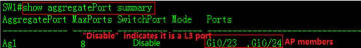
3. How to display information of AP 1
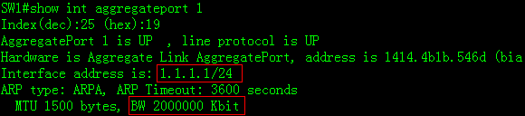
2.9.1.2 Super VLAN
Scenario
The Super VLAN function economizes IP addressresources, segregates broadcast storms, reduces virus attacks, and controls L2access on the ports. The function is suitable for extensive L2 structureenvironments with large numbers of users and VLANs and all IP addresses on asame network segment, where L2 segmentation and mutual access between certainVLANs (ARP aging for corresponding sub VLANs) are required. Common applicationscenarios include broadband access in hotels and residential areas and campus networksrun cooperatively by telecom carriers and colleges. In these scenarios, eachroom or household uses one VLAN, which is segregated from each other. However,due to limited IP address resources, it is impossible to allocate each VLANwith a network segment. A group of VLANs needs to share one network segment.For example, if VLAN 10 is allocated with the network segment 10.10.10.0/24,the household may only use one or two IP addresses, and in this case, over 200IP addresses are wasted. In addition, unified IP addresses facilitate networkmanagement for network maintenance personnel.
The Super VLAN solution issuitable for small- and medium-sized networks that require L2/L3 segmentation.Super VLAN is a function provided by an L3 switch and is implemented on the L3network. Private VLAN is a function provided by an L2 switch. Compared withPrivate VLAN, super VLAN features simpler configuration and yet lower accesscontrol flexibility. To query temporarily offline users within a Super VLAN,the gateway needs to initiate a broadcast within each sub-VLAN, and the processmay consume large CPU resources on the device.
I. NetworkingRequirements
Core switch A serves asthe user gateway and is connected to the access devices Switch B, Switch C, andSwitch D through the Trunk ports. L2 network segmentation is implementedthrough VLAN setup for access users. All VLAN users share one IP gateway for L3communication and Internet access.
II. Network Topology
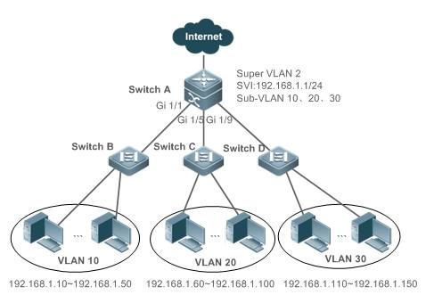
III. ConfigurationTips
1. On the access devices(Switch B, Switch C, and Switch D), configure only common VLANs (VLAN 10, VLAN20, and VLAN 30 in this example).
2. On the user gatewaydevice, create a Super VLAN and set the VLAN 10, VLAN 20, and VLAN30 of theaccess devices as sub VLANs.
3. Set the SVI port forthe Super VLAN and specify IP address ranges for each sub VLAN.
IV. ConfigurationSteps
On the core server,perform the following steps:
1. Create VLAN 2, VLAN10, VLAN 20, and VLAN 30.
Ruijie#configure terminal
Ruijie(config)#vlan 2
Ruijie(config-vlan)#exit
Ruijie(config)#vlan 10
Ruijie(config-vlan)#exit
Ruijie(config)#vlan 20
Ruijie(config-vlan)#exit
Ruijie(config)#vlan 30
Ruijie(config-vlan)#exit
2. Set VLAN 2 as theSuper VLAN and VLAN 10, VLAN 20, and VLAN 30 as its sub VLANs.
Ruijie(config)#vlan 2
Ruijie(config-vlan)#supervlan ----->configure Vlan2as Super vlan
Ruijie(config-vlan)#subvlan 10,20,30 -----> SVI port could not如果某个be added tosubvlan, need to execute command “no interface vlan vlan-id” to remove SVI portbefore adding to subvlan)
Ruijie(config-vlan)#exit
On a non-simplifiednetwork (gateway mode), Super VLAN broadcast packets are replicated to all itssub VLANs. Therefore, if a Super VLAN is configured with too many sub VLANs,the performance is undermined. Considering the packet forwarding performance,it is recommended that a Super VLAN is configured with no more than 200 subVLANs.
3. Set the L3 virtualinterface for the Super VLAN 2. The users of the sub VLANs of the Super VLAN 2communicate through the configured interface.
Ruijie(config)#interface vlan 2 ----->configure sviinterface
Ruijie(config-if-VLAN 2)#ip address 192.168.1.1 255.255.255.0
4. Set the IP addressrange of the sub VLAN 10 to 192.168.1.10 to 192.168.1.50, that of sub VLAN 20to 192.168.1.60 to 192.168.1.100, and that of sub VLAN 30 to 192.168.1.110 to192.168.1.150.
Ruijie(config)#vlan 10
Ruijie(config-vlan)#subvlan-address-range 192.168.1.10192.168.1.50
Ruijie(config-vlan)#exit
Ruijie(config)#vlan 20
Ruijie(config-vlan)#subvlan-address-range 192.168.1.60192.168.1.100
Ruijie(config-vlan)#exit
Ruijie(config)#vlan 30
Ruijie(config-vlan)#subvlan-address-range 192.168.1.110192.168.1.150
5. Set the ports Gi1/1, Gi 1/5, and Gi 1/9 as the Trunk ports for connecting Switch B, Switch C,and Switch D.
Ruijie(config)#interface range gigabitEthernet 1/1,1/5,1/9
Ruijie(config-if-range)#switchport mode trunk
6. Save theconfigurations.
Ruijie(config-if-range)#end
Ruijie#write
Note:
1. By default, theSuper VLAN agent APR function is enabled on the switch. In this case, users can access each otherbetween sub VLANs. To prevent access between sub VLANs, disable the agentfunction of the Super VLAN.
Ruijie(config)#vlan 2
Ruijie(config-vlan)#no proxy-arp
Ruijie(config-vlan)#end
2. In a DHCP environment,you do not have to specify the IP address range for a sub VLAN.
In this case, the IPaddresses are randomly allocated within one sub VLAN. The VLAN of the portconnecting the access switch determines the home sub VLAN of a PC.
Ruijie(config)#vlan 10
Ruijie(config-vlan)#subvlan-address-range 192.168.1.10192.168.1.50
Ruijie(config-vlan)#vlan 20
Ruijie(config-vlan)#subvlan-address-range 192.168.1.60192.168.1.100
Ruijie(config-vlan)#vlan 30
Ruijie(config-vlan)#subvlan-address-range 192.168.1.110192.168.1.150
3. Disable broadcaststorm prevention on the connecting port of the access switch.
When a user on anothernetwork segment accesses a user in the Super VLAN, if the user device does not exist,the switch sends ARP requests to all sub VLANs of the Super VLAN, as the SuperVLAN does not obtain the ARP information during query when resolving the userdevice ARP before forwarding the IP packet to the designated user device. Inthis case, If the Super VLAN is configured with many sub VLANs, the Super VLANhas to send a large number of ARP packets.
In a DHCP environment, ifthere are too many sub VLANs in the Super VLAN, the number of broadcast packetssent on each sub VLAN is great as well, because the broadcast packet isreplicated on each sub VLAN.
In this case, if the broadcast stormprevention function is enabled on corresponding port on the access switch, somebroadcast packets, including DHCP packets or ARP packets, are discarded. Toprevent this, you are recommended to disable the broadcast storm preventionfunction for the port on the access switch. For details, see Storm Control.
4. A Super VLAN issubject to the following restrictions:
a. A Super VLAN does not have physical interfaces as its direct member. A SuperVLAN is configured with only sub VLANs and a sub VLAN contains physicalinterfaces.
b. A Super VLAN cannot beconfigured as a sub VLAN of another Super VLAN.
c. VLAN 1 cannot beconfigured as a Super VLAN.
d. A sub VLAN cannot beconfigured as a network interface and cannot be allocated with an IP address.
V. Verification
Check the Super VLAN.
Ruijie#show supervlan
supervlan id supervlan arp-proxy subvlan id subvlanarp-proxy subvlan ip range
------------ ------------------- ----------- -----------------------------------------------------
2 ON10ON192.168.1.10 - 192.168.1.50
20ON192.168.1.60 - 192.168.1.100
30ON192.168.1.110 - 192.168.1.150
2.9.1.3 QinQ
Scenario
Business users of a network service providerusually have special requirements on the number of supported VLANs and the VLANID. The VLAN scope required by one user of a service provider may overlap withthe VLAN scope required another user. In addition, the switching channels ofVLANs of different users may mix up on the core network of the serviceprovider. However, if each user is specified with a VLAN scope, the userconfiguration will be restricted and the number of VLANs will easily exceed thelimit 4096 defined in the 802.1Q. Utilizing the IEEE 802.1Q Tunneling function,the service provider can use one VLAN (service provider VLAN) to supportmultiple VLAN users. The user VLANs is reserved. In this case, even if theusers of a network service provider are of the same VLAN, they are segregatedon the internal network of the service provider. The tunneling function extendsthe VLAN scope by using double tags. The maximum number of VLANs provided atunnel port (a port that supports IEEE 802.1Q Tunneling) reaches 4K*4K. Whenconfiguring a tunnel, you can assign a VLAN to the tunnel port as its dedicatedVLAN. In this case, the cascaded user networks require only one serviceprovider VLAN. The user traffic is packed into double-tag frames by the serviceprovider VLAN during transmission on the service provider network. The twolayers of tags of QinQ packets are transmitted on the carrier network. Theinternal tags are transmitted transparently, featuring simplicity andpracticability. It can serve an extension of core MPLS VPN in Metro EthernetVPN and become an end-to-end VPN technology.
As shown in Figure 1, the packets fromNetwork A’s VLAN 1001 are added with the outer VLAN tag 1005 before enteringthe ISP’s network. Hence, the packets carry with two tags and be propagated inthe ISP’s network by the outer VLAN tag 1005. The outer VLAN tag 1005 will bestripped when the packets leave the ISP’s network. In Network B, the packetsare propagated by VLAN tag 1001.
Figure 1-1 QinQ sketch map
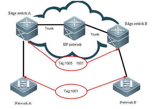
The following figure illustrates the courseof adding two tags. The ingress of edge device is dot1q-tunnle port (orabbreviated as tunnel port). All frames entering the edge device are consideredto be untagged, no matter whether are really untagged or tagged with 802.1Qtag, and then are encapsulated with the tag of ISP. VLAN ID is the default VLANof tunnel port.
Figure 1-2 Double-Tag packet structure
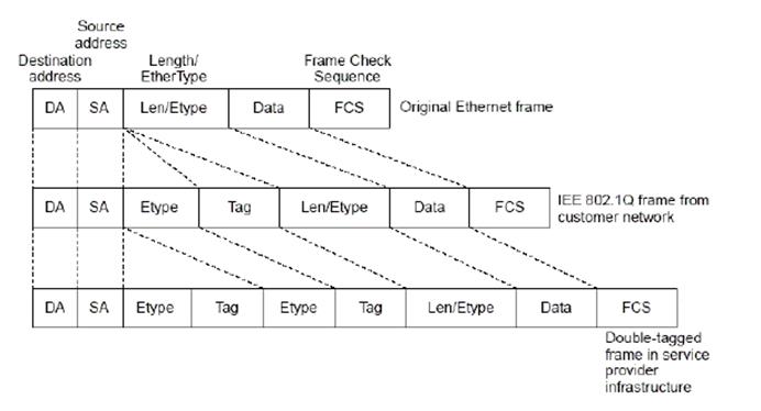
Capture the message format as follows:
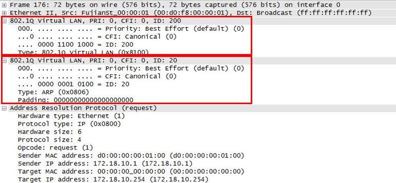
Note:
1. N18000-CB products do not support theflexible QinQ function or the VLAN MAPPING function. N18000-CB products support3 TPIDs in the global configuration mode, namely, 0x8100, 0x8100, and 0x8100.
2. N18000-ED/DB products support 4 TPIDvalues in the global configuration mode, namely, 0x8100 and 3 any values.
QinQ Port
Ruijie has brought in twonew bridge interfaces, Dot1q-Tunnel and Uplink, in QinQ implement. Thefollowing figure shows the application model:
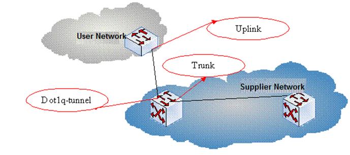
In the preceding figure,the customer bridged LAN connects to the provider bridged network through theCustomer Bridge (CB) and the Provider Bridge (PB). The service providerprovides different services and links to different customers. Data areforwarded on the customer bridged LAN with C-TAGs and are added with (orstripped of) S-TAGs on the customer network port for transmission on theservice provider network. Data forwarding on the provider bridged network istransparent compared with data transmission on the customer bridged LAN.
Tunnel Port
Utilizing the IEEE 802.1QTunneling function, the service provider can use one VLAN (service providerVLAN) to support multiple VLAN users. The user VLANs is reserved. In this case,even if the users of a network service provider are of the same VLAN, they aresegregated on the internal network of the service provider. The tunnelingfunction extends the VLAN scope by using double tags. The port that supportsIEEE 802.1Q Tunneling is called a tunnel port. When configuring a tunnel, youcan assign a VLAN to the tunnel port as its dedicated VLAN. In this case, thecascaded user networks require only one service provider VLAN. The user trafficis packed into double-tag frames by the service provider VLAN duringtransmission on the service provider network.
Uplink port
Uplink port essentiallyis a special trunk port. The difference is that the packets outputted from theuplink port are tagged, but the packets outputted from the trunk port (whenthey are forwarded from native VLAN) are untagged. A typical example is theport of a user network connecting to an ISP network.
QinQ Classification
Basic QinQ
Basic QinQ is enabledbased on port. When tunnel port is configured, the device will add the VLAN tagof the default VLAN of the tunnel port to the packet arriving the tunnel port.If the packet is already of a VLAN tag, this means it has two tags. Basic QinQis simple, but the encapsulation of outer VLAN tag is not flexible enough.
Flexible QinQ
Flexible QinQ canflexibly encapsulate different outer VLAN tags for different flows by flowclassification method like user VLAN tag, MAC address, IP protocol, sourceaddress, destination address, priority or port number of application program.
You can:
n Addouter VLAN tag by inner VLAN tag
n Modifyinner VLAN tag by outer VLAN tag
n Modifyouter VLAN tag by inner VLAN tag
n Addouter VLAN tag by ACL
n Modifyouter VLAN tag by ACL
nModify inner VLAN tag by ACL
Restriction of QinQConfiguration
The followingrestrictions apply to QinQ configuration:
n Therouted ports cannot be configured as tunnel ports.
n The802.1x function cannot be enabled on the port configured as a tunnel port.
n Portsecurity cannot be enabled on the port configured as a tunnel port.
n Forthe ACL applied on the tunnel port, the inner keyword is necessary to match theVID of user tag.
n Itis recommended to configure the egress of user network connecting the ISPnetwork as uplink port as well. If the TPID of ISP tag is set on theQinQ-enabled port of the user network, the TPID of ISP tag of uplink portshould be set with the same value.
n QinQdoes not support hot backup.
n TheMTU of a port is 1500 bytes by default. A packet will be increased by 4 byteswhen it is added with outer VLAN tag. It is recommended to increase the MTUvalue of ports in ISP network at an appropriate extent, or at least 1504 bytes.
nOnce QinQ is enabled on a port,to enable IGMP Snooping, you need set SVGL sharing mode or otherwise IGMPSnooping does not function on the port with QinQ enabled.
2.9.1.3.1 Basic QinQ
I. NetworkingRequirements
Customer PCs on VLAN 10and VLAN 20 are connected to the access switch. The Trunk port of the accessswitch is connected to the convergence switch. The convergence switch requiresbasic QinQ functions and adds external tag VLAN 1000 to tagged data streamforwarded by access users.
II. Network Topology
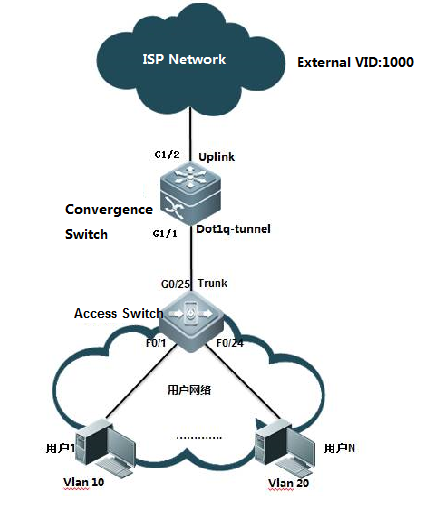
III. ConfigurationTips
1. On the convergenceswitch, set the port that connects the carrier network as an uplink port andconfigure the QinQ function on the port that connects the access switch.
2. On the access switch,create the related VLANs, set the port that connects users as an access portand the port that connects the convergence switch as a trunk port.
IV. ConfigurationSteps
On the convergenceswitch, perform the following steps:
1. Create the external VLAN 1000.
Ruijie#configure terminal
Ruijie(config)#vlan 1000
Ruijie(config-vlan)#exit
Ruijie(config)#
2. Enable the basic QinQfunctions on the port that connects the access switch.
Ruijie(config)#interface gigabitEthernet 1/1
Ruijie(config-if-GigabitEthernet 1/1)#switchport modedot1q-tunnel ----->configure interface G1/1 as dot1q-tunnel
Ruijie(config-if-GigabitEthernet 1/1)#switchport dot1q-tunnelnative vlan 1000 ----->configure vid of dot1q-tunnel as 1000
Ruijie(config-if-GigabitEthernet 1/1)#switchport dot1q-tunnelallowed vlan add untagged 1000
3. Set the port thatconnects the carrier network as an uplink port.
Ruijie(config)# interface gigabitEthernet 1/2
Ruijie(config-if-GigabitEthernet 1/2)#switchport mode uplink
4. On the uplink port,modify the TPID value of output packets to a value identifiable by athird-party devices, which is 0x9100. (This step is optional. Thedefault TPID for Ruijie devices is 0x8100.) The TPIDs for devices varywith manufactures. For example, the default TPID for Huawei devices is 0x9100.To interconnect with Huawei devices, you need to change the TPID to 0x9100.
Ruijie(config-if-GigabitEthernet 1/2)#frame-tag tpid 9100
On the access switch,perform the following steps:
Ruijie(config)#vlan range 10,20
Ruijie(config-vlan-range)#exit
Ruijie(config)#interface range f0/1-12
Ruijie(config-if-range)#switchport access vlan 10
Ruijie(config-if-range)#exit
Ruijie(config)#interface range f0/13-24
Ruijie(config-if-range)#switchport access vlan 20
Ruijie(config-if-range)#exit
Ruijie(config-if-GigabitEthernet 0/25)#switchport mode trunk
Ruijie(config-if-GigabitEthernet 0/25)#end
Note:
1. In a QinQconfiguration model, if the uplink port connects edge devices to the serviceprovider network is a Trunk port or Hybrid port, do not set the native VLAN ofthe Trunk port or Hybrid port to the default VLAN of the tunnel port, becausewhen a packet is output on the Trunk port or Hybrid port, the tag containingits native VLAN ID is removed from the packet.
2. When the QinQ functionis enabled, the device encapsulates user packets with the external VLAN tag,rather than forwarding the packets based on the original VLAN specified in thepackets. Therefore, you do not have to create VLANs for users on the device.(The configuration of user VLANs has no influence on the network.)
3. An uplink port is aspecial Trunk port. The difference is that packets sent from an uplink portare tagged, while packets sent from an Trunk port are untagged if they areforwarded by the native VLAN.
4. In basic QinQconfiguration, the port adds external tags no matter to the received packets nomatter whether they are tagged or not. If the received packet has a VLANtag, the packet becomes a double-tag packet. If the received packet doesnot have a VLAN tag, the packet becomes a packet with a default VLAN tag.
5. The basic QinQfunction does not support the identification and retention of management VLANtags without adding external tags during packet forwarding.
6. At present, all Ruijieswitches do not support the termination of QinQ tags. That is, the two layersof tags cannot be resolved on one switch. To resolve two layers of tags, youneed to add a switch.
V. Verification
1. Check whether the QinQfunction is enabled on the port.
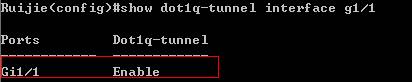
2. Check the TPID valueon the port.
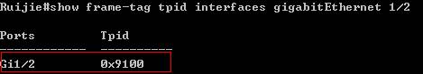
2.9.1.3.2 Flexible QinQ - VID-Based QinQ
I. NetworkingRequirements
1. The convergence switchimplements flexible QinQ based on the user VLAN tag classification. Add datastreams from user VLAN 101 to user VLAN 200 with external tags VLAN 101 anddata streams from user VLAN 201 to user VLAN 300 with external tags VLAN 201.
2. Manage the accessswitches. The management VLAN is 500. Data streams from the VLAN are forwardedwithout adding external tags and their original tags are retained.
II. Network Topology
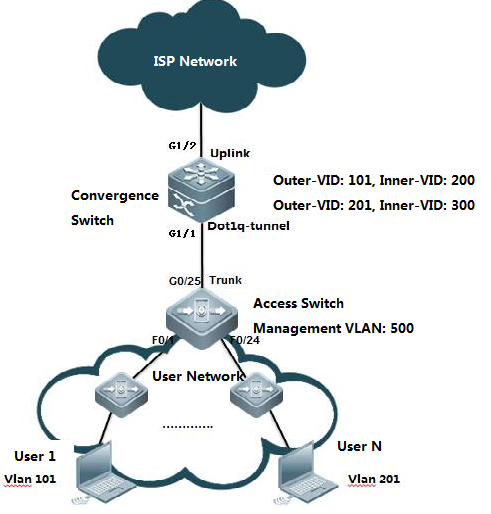
III. ConfigurationTips
1. On the convergenceswitch, configure user VLAN tag-based flexible QinQ on the port that connectsthe floor distribution switch.
Flexible QinQ planning onuser VLAN tag-based data stream tagging with external VLANs
| Device | Service | User VLAN Tag | External VLAN Tag | Classification Rules |
| Convergence switch | Internet access service for users | 101-200 | 101 | User VLAN scope |
| Convergence switch | Internet access service for users | 201-300 | 201 | User VLAN scope |
2. Set the managementVLAN on the floor distribution switch to a native VLAN and the management VLANon the access switch to the native VLAN of dot1q-tunnel.
IV. ConfigurationSteps
On the convergenceswitch, perform the following steps:
1. Create ISP VLANs 101and 201 to identify different service data types.
Ruijie#configure terminal
Ruijie(config)#vlan 101
Ruijie(config-vlan)#exit
Ruijie(config)#vlan 201
Ruijie(config-vlan)#exit
Ruijie(config)#vlan 500
Ruijie(config-vlan)#exit
2. On the downlink portof the convergence switch, configure the flexible QinQ function for addingexternal VLAN tags based on the user VLAN.
Ruijie(config)#interface gigabitEthernet 1/1
Ruijie(config-if-gigabitEthernet 1/1)# switchport modedot1q-tunnel
Ruijie(config-if-gigabitEthernet 1/1)# switchportdot1q-tunnel allowed vlan add untagged 101,201,500
Ruijie(config-if-gigabitEthernet 1/1)# dot1q outer-vid 101register inner-vid 101-200
Ruijie(config-if-gigabitEthernet 1/1)# dot1q outer-vid 201 registerinner-vid 201-300
Ruijie(config-if-gigabitEthernet 1/1)# switchportdot1q-tunnel native vlan 500
Ruijie(config)# interface gigabitEthernet 1/2
Ruijie(config-if-GigabitEthernet 1/2)#switchport mode uplink
On the access switch,perform the following steps:
1. Create the user VLANsbased on the user ports and configure the management VLAN and management IPaddress.
2. Set the uplink port asa Trunk port and set the native VLAN to VLAN 500.
Ruijie(config)# interface gigabitEthernet 0/25
Ruijie(config-if-GigabitEthernet 0/25)#switchport mode trunk
Ruijie(config-if-GigabitEthernet 0/25)#switchport trunknative vlan 500
Ruijie(config-if-GigabitEthernet 0/25)#end
Note:
1. An uplink port is aspecial Trunk port. The difference is that packets sent from an uplink port aretagged. while packets sent from an Trunk port are untagged if they areforwarded by the native VLAN.
2. The flexible QinQfunction allows the retention of management VLAN tags without adding externaltags during packet forwarding.
3. At present, all Ruijieswitches do not support the termination of QinQ tags. That is, the two layersof tags cannot be resolved on one switch. To resolve two layers of tags, youneed to add a switch.
4. An external tag can bethe same as or different from the internal tag. (For example, in the example,the internal tags ranges from 101 to 200 and the external tag is 101.)
5. If the customer hastwo management VLANs, and tags of both management VLANs in the data streams areto be retained without adding the streams with external tags, do asfollows:
1. Network topology
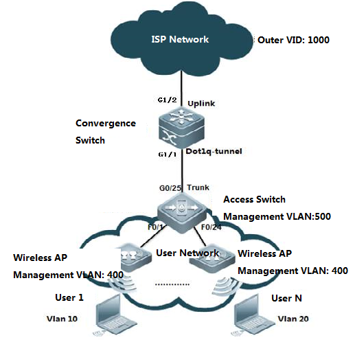
2. Customer requirement
The customer has twomanagement VLANs. One is the wireless AP management VLAN 400 and the other isthe access switch management VLAN 500. Data streams with tags of either of thetwo VLAN are to be forwarded directly without being added with external tags.
For data streams taggedwith user VLANs, add external tags VLAN 1000.
3. Run the switchconfiguration commands.
The convergence switchconfiguration commands are as follows:
vlan 400
vlan 500
vlan 1000
interface GigabitEthernet1/1
switchport mode dot1q-tunnel
switchport dot1q-tunnel allowed vlan add tagged 400
switchport dot1q-tunnel allowed vlan add untagged 500,1000
switchport dot1q-tunnel native vlan 500
dot1q outer-vid 400 register inner-vid 400
dot1q outer-vid 1000 register inner-vid 10,20
interface GigabitEthernet 1/2
switchport mode hybrid
switchport hybrid allowed vlan add untagged 400
Tagged packet forwarding
1. Packets tagged withthe switch management VLAN 500 are processed in an original manner. Theuplink port on the access switch removes the VLAN 500 tag. The convergenceswitch then adds the VLAN 500 tag and forwards the packet through the uplinkport to the ISP network. In the reverse direction, the dotq-tunnel port removesthe VLAN 500 tag and forwards the packet to the access switch.
2. Packets tagged withthe wireless AP management VLAN 400 are processed in a different manner.When the wireless AP management VLAN data streams reach the access switch, thedata streams with VLAN 400 tags are forwarded directly to the dot1q-tunnel porton the convergence switch and are added with another VLAN 400 tag. Then, eachAP management data packet has two VLAN 400 tags. When the double-taggedwireless AP management VLAN data streams are forwarded from the uplink port,their external tags are removed and the data streams contain only one layers oftags. This is because the uplink port is set as a Hybrid port and VLAN 400 isset to untag. The data streams returning from the ISP network containone layer of VLAN 400 tags and the VLAN 400 tags are not removed beforeforwarding due to the configuration switchport dot1q-tunnel allowed vlan addtagged 400.
4. On the access switch,do as follows:
Create the user VLANsbased on the user ports and configure the management VLAN and management IPaddress.
Set the uplink port as aTrunk port and set the native VLAN to VLAN 500.
Ruijie(config)# interface gigabitEthernet 0/25
Ruijie(config-if-GigabitEthernet 0/25)#switchport mode trunk
Ruijie(config-if-GigabitEthernet 0/25)#switchport trunknative vlan 500
Ruijie(config-if-GigabitEthernet 0/25)#end
V. Verification
1. Check that theconfigurations are correct. Check whether the downlink port is a dot1q-tunnelport, whether the VLAN in the external tag is added to the approved VLAN liston the port, whether the mapping policy on the port is correct, and whether theuplink port configuration is correct.
Ruijie#show running-config interface gigabitEthernet 1/1
interface GigabitEthernet 1/1
switchport mode dot1q-tunnel
switchport dot1q-tunnel allowed vlan add untagged 101,201,500
dot1q outer-vid 101 register inner-vid 101-200
dot1q outer-vid 201 register inner-vid 201-300
switchport dot1q-tunnel native vlan 500
spanning-tree bpdufilter enable
Ruijie#show running-config interface gigabitEthernet 1/2
interface GigabitEthernet 1/2
switchport mode uplink
2. Check the QinQ configurationon the port of the device again. The check items are the same as that of step1.
Ruijie#show interfaces dot1q-tunnel
========Interface Gi1/1========
Native vlan: 500
Allowed vlan list:1,101,201,500
Tagged vlan list:
3. Check the mappingpolicies of internal tags and external tags and ensure that the VLANs intheexternal tags map correct to the VLANs in the internal tags.
Ruijie#show registration-table
Ports Type Outer-VID Inner-VID-list
------ ---------- ---------- --------------
Gi1/1 Add-outer 101 101-200
Gi1/1 Add-outer 201 201-300
2.9.1.3.3 Flexible QinQ - Stream-based QinQ
I. NetworkingRequirements
1. The convergence switchimplements flexible QinQ based on the user data stream classification. For user data streams of the network segment 192.168.10.0/24, addexternal tags VLAN 1000.For user data streams of the network segment 192.168.20.0/24, addexternal tags VLAN 1001.
2. Manage the accessswitches. The management VLAN is 500. Data streams from the VLAN are forwardedwithout adding external tags and their original tags are retained.
II. Network Topology
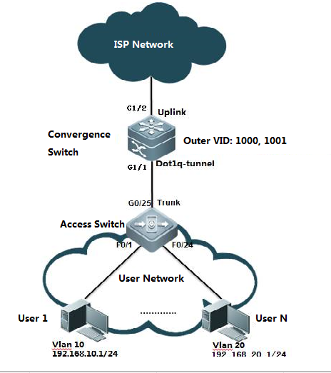
III. ConfigurationTips
1. On the access switch, configure the userdata stream-based flexible QinQ on the port that connects the floordistribution switch. For user data streams of the network segment 192.168.10.0/24, addexternal tags VLAN 1000.For user data streams of the network segment 192.168.20.0/24, addexternal tags VLAN 1001.
2. Set the managementVLAN on the floor distribution switch to a native VLAN and the management VLANon the access switch to the native VLAN of dot1q-tunnel.
3. At present, all Ruijieswitches do not support the termination of QinQ tags. That is, the two layersof tags cannot be resolved on one switch. To resolve two layers of tags, youneed to add a switch.
IV. ConfigurationSteps
On the convergenceswitch, perform the following steps:
1. Create ISP VLANs 1000and 1001 to identify different service data types.
Ruijie#configure terminal
Enter configuration commands, one per line. End with CNTL/Z.
Ruijie(config)#vlan 1000
Ruijie(config-vlan)#exit
Ruijie(config)#vlan 1001
Ruijie(config-vlan)#exit
Ruijie(config)#vlan 500
Ruijie(config-vlan)#exit
2. Create the user data stream-basedACL.
Ruijie(config)#ip access-list standard vlan10
Ruijie(config-std-nacl)#permit 192.168.10.0 0.0.0.255
Ruijie(config-std-nacl)#exit
Ruijie(config)#ip access-list standard vlan20
Ruijie(config-std-nacl)#permit 192.168.20.0 0.0.0.255
Ruijie(config-std-nacl)#exit
Ruijie(config)#
3. Enable the data-streambased flexible QinQ function on the convergence switch.
Ruijie(config)#interface gigabitEthernet 1/1
Ruijie(config-if-GigabitEthernet 1/1)# switchport modedot1q-tunnel
Ruijie(config-if-GigabitEthernet 1/1)# switchportdot1q-tunnel allowed vlan add untagged 1000,1001,500
Ruijie(config-if-GigabitEthernet 1/1)# traffic-redirectaccess-group vlan10 nested-vlan 1000 in
Ruijie(config-if-GigabitEthernet 1/1)# traffic-redirectaccess-group vlan20 nested-vlan 1001 in
Ruijie(config-if-GigabitEthernet 1/1)# switchportdot1q-tunnel native vlan 500
4. Configure the uplinkport.
Ruijie(config)# interface gigabitEthernet 1/2
Ruijie(config-if-GigabitEthernet 1/2)#switchport mode uplink
On the access switch,perform the following steps:
1. Create the user VLANsbased on the user ports and configure the management VLAN and management IPaddress.
2. Set the uplink port asa Trunk port and set the native VLAN to VLAN 500.
Ruijie(config)# interface gigabitEthernet 0/25
Ruijie(config-if-GigabitEthernet 0/25)#switchport mode trunk
Ruijie(config-if-GigabitEthernet 0/25)#switchport trunknative vlan 500
Ruijie(config-if-GigabitEthernet 0/25)#end
V. Verification
1. Check that theconfigurations are correct. Check whether the downlink port is a dot1q-tunnelport, whether the VLAN in the external tag is added to the approved VLAN liston the port, whether the mapping policy on the port is correct, and whether theuplink port configuration is correct.
Ruijie#show running-config interface gigabitEthernet 1/1
interface GigabitEthernet 1/1
switchport mode dot1q-tunnel
switchport dot1q-tunnel allowed vlan add untagged500,1000-1001
switchport dot1q-tunnel native vlan 500
traffic-redirect access-group vlan10 nested-vlan 1000 in
traffic-redirect access-group vlan20 nested-vlan 1001 in
spanning-tree bpdufilter enable
Ruijie#show running-config interface gigabitEthernet 1/2
interface GigabitEthernet 1/2
switchport mode uplink
2. Check the QinQconfiguration on the port of the device again. The check items are the same asthat of step 1.
Ruijie#show interfaces dot1q-tunnel
========Interface Gi1/1========
Native vlan: 500
Allowed vlan list:1,1000,1001,500
Tagged vlan list:
3. Check whether the ACLis correct.
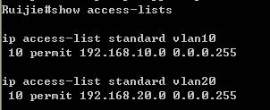
4. Check the mappingpolicies for stream-based tagging.
Ruijie#show traffic-redirect
PortsTypeVID Match-filter
------------ ----------- ---- ------------
Gi1/1Nested-vid 1000 vlan10
Gi1/1Nested-vid 1001 vlan20
2.9.2 IP addressing and Application
2.9.2.1 DHCP Server
Scenario
The DHCP (Dynamic Host Configuration Protocol),specified in RFC 2131, provides configuration parameters for hosts over theInternet. The DHCP works in the client/server mode. The DHCP server assigns IPaddresses for the hosts dynamically and provides configuration parameters.
The DHCP assigns IP address in three ways:
Assign IP addresses automatically. The DHCP serverassigns permanent IP addresses to the clients;
Assign IP addresses dynamically. The DHCP serverassigns IPaddresses that will expire after a period of time to the clients (orthe clients can release the addresses by themselves);
Configure IP addresses manually. Network administratorsspecify IP addresses and send the specified IP addresses to the clients throughthe DHCP.
Among the above mentioned three methods, only dynamicassignment allows reuse of the IP address that the client does not need anymore.
The format of DHCP message is based on that of BOOTP(Bootstrap Protocol) message. Hence, it is necessary for the device to be ableto act as the BOOTP relay agent and interact with the BOOTP client and the DHCPserver. The function of BOOTP relay agent eliminates the need of deploying aDHCP server in every physical network. The DHCP is detailed in RFC 2131 and RFC2132.
The DHCP protocol is widely used to dynamically assignreusable network resources, for example, IP addresses. A DHCP client sendsDISCOVER broadcast packets to a DHCP server. After receiving the DISCOVERpackets, the DHCP server will assign resources, e.g. IP addresses, by a certainpolicy in OFFER packets sent to the client. Once receiving the OFFER packets,the DHCP client verifies the availability of the resource. If the resource isavailable, it will send a REQUEST packet; otherwise, it will re-send theDISCOVER packet. Once the server receives the REQUEST packet, it will verifywhether the IP address or other limited resource can be assigned. If so, theserver will send an ACK packet; otherwise, it will send a NAK packet. Once theDHCP client receives the ACK packet, it will start using the resource assignedby the server; if the NAK packet is received, the client may re-send theDISCOVER packet.
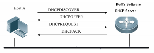
Generally, common switch support to allocate at most2000 IP address. S86E support to allocate at most 8000 IP address.
I. Requirements
All users are on Vlan 10 and their gatewayis on Core switch. Core switch acts as DHCP Server and assigns IP address toall users.
II. Network Topology
III. Configuration Tips
1. Assign ports connected to users on accessswitch to Vlan 10
2. Configure Core switch as DHCP Server andit assigns IP address to users.
3. DHCP Server allocates IP gateway (itself), DNS server and lease(24H by default) to users.
IV. ConfigurationSteps
Core switch:
1. Enable DHCP service
Ruijie(config)#servicedhcp ------>DHCP service is disabled by default.
2. Assign IP address to Vlan 10
Ruijie(config)#interfacevlan 10
Ruijie(config-if-VLAN10)#ip address 192.168.1.254 255.255.255.0
Ruijie(config-if-VLAN10)#exit
3. Create DHCP pool and configure DHCPparameters ---gateway , DNS , subnets.
Ruijie(config)#ipdhcp pool vlan10
Ruijie(dhcp-config)#network192.168.1.0 255.255.255.0 ------>Network subnets
Ruijie(dhcp-config)#dns-server218.85.157.99 ------>DNS server
Ruijie(dhcp-config)#default-router192.168.1.254 ------>User Gateway
Ruijie(dhcp-config)#end
Ruijie#wr
Access switch:
Assign ports connected to users to Vlan 10
Ruijie(config)#intrange fastEthernet 0/1-2
Ruijie(config-if-range)#switchportaccess vlan 10
V. Verification
1. How to display DHCP assignments
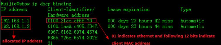
2. To display NIC information on a station,execute "run-------->cmd-------->ipconfig/all"
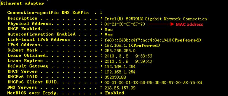
2.9.2.2 DHCP Relay
Overview
The DHCP relay agent forwards DHCP packets between theDHCP server and the DHCP clients. When the DHCP clients and the server are notlocated in the same subnet, a DHCP relay agent must be available for forwardingthe DHCP request and response messages. Data forwarding by the DHCP relay agentis different from general forwarding. In general forwarding, IP packets areunaltered and the transmission is transparent. However, upon receiving a DHCPmessage, the DHCP relay agent regenerates and forwards a DHCP message.
From the perspective of the DHCP client, the DHCP relayagent works like a DHCP server. From the perspective of the DHCP server, theDHCP relay agent works like a DHCP client.
The DHCP relay forwards the DHCP request packetreceived in the form of unicast to the DHCP server, at the same time, forwardsthe DHCP response packet received to the DHCPclient. The DHCP relay serves as aforwarding station, responsible for the communication between the DHCP clientsand the DHCP servers at different network segments. In this way, only one DHCPserver can dynamically manage IP addresses at multiple segments, that is, theDHCP dynamic IP management in the Client-Relay-Server mode, as shown below:
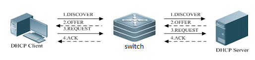
I. Requirements
Distribution switch is the user gatewaywhich have enabled DHCP relay. Core switch acts as DHCP Server.Connect coreswitch and distribution switch through Layer 3 link.
II. Network Topology
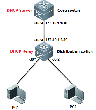
III. Configuration Tips
1. Enable DHCP relay on distribution switch
2. Enable DHCP Service on Core switch
IV. ConfigurationSteps
Core switch:
1. Convert the port connected todistribtuion switch to L3 port and assign a IP address to it.
Ruijie(config)#interfacegigabitEthernet 0/24
Ruijie(config-if-GigabitEthernet0/24)#no switchport
Ruijie(config-if-GigabitEthernet0/24)#ip address 172.16.1.1 255.255.255.252
Ruijie(config-if-GigabitEthernet0/24)#exit
2. Configure a static route.
Ruijie(config)#iproute 192.168.1.0 255.255.255.0 172.16.1.2
3. Enable DHCP service
Ruijie(config)#servicedhcp ------>DHCP service is disabled by default.
4. Create DHCP pool and configure DHCPparameters ---gateway , DNS , subnets
Ruijie(config)#ipdhcp pool vlan10
Ruijie(dhcp-config)#network192.168.1.0 255.255.255.0 ------>Network subnet
Ruijie(dhcp-config)#dns-server218.85.157.99 ------>DNS Server
Ruijie(dhcp-config)#default-router192.168.1.254 ------>User Gateway
Ruijie(dhcp-config)#exit
5. Save configuration
Ruijie(config)#end
Ruijie#wr
Aggregation switch:
1. Assign IP address to Vlan 10 and SVI 10is user gateway
Ruijie(config)#interfacevlan 10
Ruijie(config-if-VLAN10)#ip address 192.168.1.254 255.255.255.0
Ruijie(config-if-VLAN10)#exit
2. Convert port connected to Core switch tolayer 3 port and assign IP address to it
Ruijie(config)#interfacegigabitEthernet 0/24
Ruijie(config-if-GigabitEthernet0/24)#no switchport
Ruijie(config-if-GigabitEthernet0/24)#ip address 172.16.1.2 255.255.255.252
Ruijie(config-if-GigabitEthernet0/24)#exit
3. Configure default route
Ruijie(config)#iproute 0.0.0.0 0.0.0.0 172.16.1.1
4. Enable DHCP service
Ruijie(config)#servicedhcp ------>DHCP service isdisabled by default
5. Enable DHCP relay
Ruijie(config)#iphelper-address 172.16.1.1 ------>172.16.1.1 isthe DHCP Server
6. Save configuration
Ruijie(config)#end
Ruijie#wr
V. Verification
1. How to display DHCP assignments
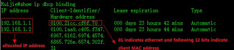
2. To display NIC information on a station,execute "run-------->cmd-------->ipconfig/all"

3. How to display status of DHCP relay
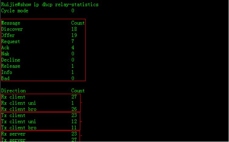
2.9.2.3 GRE Tunnel
Function Overview
Generic Routing Encapsulation (GRE) is aprotocol that encapsulates data packets of certain network layer protocols (forexample, IP and IPX) so that encapsulated data packets can be transmitted inanother network layer protocol (IP). The path where the encapsulated datapackets are transmitted on the network are called a GRE tunnel. A GRE tunnel isa virtual point-to-point connection, with the devices on its two endencapsulating and decapsulating the data packets.
I. NetworkingRequirements
Switch A and Switch B areconnected to each other over the Internet. The two subnets Group 1 and Group 2of the private network that runs the IP are connected to each other through aGRE tunnel between two switches.
II. Network Topology
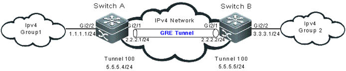
III. ConfigurationTips
The configuration of aGRE tunnel covers the following:
1. Tunnel interface No.
2. Tunnel mode (GRE IPmode in this example)
3. Source address of thetunnel
4. Destination address ofthe tunnel
5. Route of the tunnel
Note: If the addresses ofthe tunnel interfaces at the two ends of the tunnel are not in the same networksegment, configure the forwarding route of the tunnel from the one end to theremote end so that the encapsulated packets can be forwarded properly. You canconfigure a static route or a dynamic one. Configure the route on both ends ofthe tunnel. For two or more tunnel interfaces complying with the sameencapsulation protocol, do not use the same source address or destinationaddress. If the source address is configured in the source interface format forthe tunnel interface, the source address is the main IP address of the sourceinterface.
IV. ConfigurationSteps
Note: The IPv4 packet routebetween Switch A and Switch B is configured and reachable.
1. On Switch A,configure the following items:
Interface that connectsthe IPv4 external network
SwitchA#configureterminal
SwitchA(config)#interface GigabitEthernet 2/1
SwitchA(config-if)#ip address 2.2.2.1 255.255.255.0
Interface that connectsthe IPv4 internal network
SwitchA#configure terminal
SwitchA(config)#interface GigabitEthernet 2/2
SwitchA(config-if)#ip address 1.1.1.1 255.255.255.0
Interface of the GRE IPtunnel
SwitchA#configure terminal
SwitchA(config)#interface Tunnel 100
SwitchA(config-if-Tunnel 100)#tunnel mode gre ip
SwitchA(config-if-Tunnel 100)#ip address 5.5.5.4255.255.255.0
SwitchA(config-if-Tunnel 100)#tunnel source 2.2.2.1
SwitchA(config-if-Tunnel 100)#tunnel destination 2.2.2.2
Route for entering thetunnel
SwitchA#configureterminal
SwitchA(config)#ip route 3.3.3.0 tunnel 100
2. On Switch B,configure the following items:
SwitchB#configure terminal
SwitchB(config)#interface GigabitEthernet 2/1
SwitchB(config-if)#ip address 2.2.2.2 255.255.255.0
SwitchB#configure terminal
SwitchB(config)#interface GigabitEthernet 2/2
SwitchB(config-if)#ip address 3.3.3.1 255.255.255.0
SwitchB#configure terminal
SwitchB(config)#interface Tunnel 100
SwitchB(config-if-Tunnel 100)#tunnel mode gre ip
SwitchB(config-if-Tunnel 100)#ip address 5.5.5.5255.255.255.0
SwitchB(config-if-Tunnel 100)#tunnel source 2.2.2.2
SwitchB(config-if-Tunnel 100)#tunnel destination 2.2.2.1
SwitchB#configure terminal
SwitchB(config)#ip route 1.1.1.0 tunnel 100
V. Verification
1. Check the tunnelinterface status on Switch A and Switch B.
SwitchA#show interface tunnel 100
Index(dec):9 (hex):9
Tunnel 100 is UP , line protocol is UP
Hardware is Tunnel
Interface address is: 5.5.5.4/24
Interface IPv6 address is:
No IPv6 address
MTU 1476 bytes, BW 9 Kbit
Encapsulation protocol is Tunnel, loopback not set
Keepalive interval is 10 sec ,retries 0.
Carrier delay is 2 sec
Tunnel attributes:
Tunnel source 2.2.2.1, destination 2.2.2.2, routable
Tunnel TOS/Traffic Class not set, Tunnel TTL 254
Tunnel config nested limit is 4, current nested number is 0
Tunnel protocol/transport is greip
Tunnel transport VPN is no set
Key disabled, Sequencing disabled
Checksumming of packets disabled
RX packets
Drop reason(Down: 0, Checksum error: 0, sequence error: 0,routing: 0)
TX packets
Drop reason(Too big: 0, Payload Type error: 0,Nested-limit: 0)
Rxload is 1/255, Txload is 1/255
10 seconds input rate 0 bits/sec, 0 packets/sec
10 seconds output rate 0 bits/sec, 0 packets/sec
0 packets input, 0 bytes, 0 no buffer, 0 dropped
Received 0 broadcasts, 0 runts, 0 giants
0 input errors, 0 CRC, 0 frame, 0 overrun, 0 abort
0 packets output, 0 bytes, 0 underruns , 0 dropped
0 output errors, 0 collisions, 0 interface resets
SwitchB#show interface tunnel 100
Index(dec):9 (hex):9
Tunnel 100 is UP , line protocol is UP
Hardware is Tunnel
Interface address is: 5.5.5.5/24
Interface IPv6 address is:
No IPv6 address
MTU 1476 bytes, BW 9 Kbit
Encapsulation protocol is Tunnel, loopback not set
Keepalive interval is 10 sec ,retries 0.
Carrier delay is 2 sec
Tunnel attributes:
Tunnel source 2.2.2.2, destination 2.2.2.1, routable
Tunnel TOS/Traffic Class not set, Tunnel TTL 254
Tunnel config nested limit is 4, current nested number is 0
Tunnel protocol/transport is greip
Tunnel transport VPN is no set
Key disabled, Sequencing disabled
Checksumming of packets disabled
RX packets
Drop reason(Down: 0, Checksum error: 0, sequence error: 0,routing: 0)
TX packets
Drop reason(Too big: 0, Payload Type error: 0,Nested-limit: 0)
Rxload is 1/255, Txload is 1/255
10 seconds input rate 0 bits/sec, 0 packets/sec
10 seconds output rate 0 bits/sec, 0 packets/sec
0 packets input, 0 bytes, 0 no buffer, 0 dropped
Received 0 broadcasts, 0 runts, 0 giants
0 input errors, 0 CRC, 0 frame, 0 overrun, 0 abort
0 packets output, 0 bytes, 0 underruns , 0 dropped
0 output errors, 0 collisions, 0 interface resets
2. Ping to the IPv4address of the remote interface on Switch A.
SwitchA#ping2.2.2.2
Sending 5, 100-byte ICMP Echoes to 2.2.2.2, timeout is 2seconds:
< press Ctrl+C to break >
!!!!!
Success rate is 100 percent (5/5), round-trip min/avg/max =1/2/10ms
2.9.3 IP Routing
2.9.3.1 Static Routes
Overview
Static routes are manually configured so that thepackets can be sent to the specified destination network go through thespecified route. Static routes can be very important if the switch don'tsupport dynamic routing protocol(RIP,OSPF etc.) and are useful for specifying agateway of last resort to which all unroutable packets are sent.
I. Requirements
Configure theswitch with static routes and ensure that users in network 1 can communicatewith users in network 2
II. Network Topology
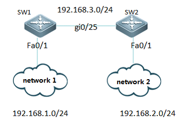
III. Configuration Tips
1. Assign IP addresses to SW1 and SW2
2. ConfigureStatic Routes on SW1
3. ConfigureStatic Routes on SW2
4. SaveConfiguration
IV. ConfigurationSteps
1. Assign IPaddress to SW1
Ruijie>enable
Ruijie#configureterminal
Ruijie(config)#interfacefastethernet 0/1
Ruijie(config-if-FastEthernet0/1)#no switchport
Ruijie(config-if-FastEthernet0/1)#ip address 192.168.1.254 255.255.255.0
Ruijie(config-if-FastEthernet0/1)#interface GigabitEthernet 0/25
Ruijie(config-if-GigabitEthernet0/25)#no switchport
Ruijie(config-if-GigabitEthernet0/25)#ip address 192.168.3.1 255.255.255.0
Ruijie(config-if-GigabitEthernet0/25)#exit
2. Assign IPaddress to SW2
Ruijie>enable
Ruijie#configureterminal
Ruijie(config)#interfacefastethernet 0/1
Ruijie(config-if-FastEthernet0/1)#no switchport
Ruijie(config-if-FastEthernet0/1)#ip address 192.168.2.254 255.255.255.0
Ruijie(config-if-FastEthernet0/1)#interface GigabitEthernet 0/25
Ruijie(config-if-GigabitEthernet0/25)#no switchport
Ruijie(config-if-GigabitEthernet0/25)#ip address 192.168.3.2 255.255.255.0
Ruijie(config-if-GigabitEthernet0/25)#exit
3. ConfigureStatic Routes on SW1
Note:
1.When youconfigure static routes , there're two ways to specify next hop.You can specifyan IP address ,or you can specify a local outgoing interface.
2.We suggest youto use IP address as next hop
Ruijie(config)#iproute 192.168.2.0 255.255.255.0 192.168.3.2 -----> configurestatic routes to destination subnet 192.168.2.0/24 and nexthop is 192.168.3.2
4. Configure Static Routes on SW2
Ruijie(config)#iproute 192.168.1.0 255.255.255.0 192.168.3.1 ----->configure staticroutes to destination subnet 192.168.1.0/24 and nexthop is 192.168.3.1
5. Save Configuration
Ruijie(config)#end
Ruijie#write
V. Verification
1. You can use "ping" on a station in network1 to verify network connectivity
"run"-->"cmd"-->"pingx.x.x.x" (x.x.x.x is a host in network 2)
2. How to display ip routing table
Ruijie#showip route
Codes: C - connected, S - static, R - RIP, B - BGP
O - OSPF, IA - OSPF inter area
N1 - OSPF NSSA external type 1, N2 - OSPF NSSA external type 2
E1 - OSPF external type 1, E2 - OSPF external type 2
i - IS-IS, su - IS-IS summary, L1 - IS-IS level-1, L2 - IS-IS level-2
ia - IS-IS inter area, * - candidate default
Gatewayof last resort is no set
S 192.168.2.0/24 [1/0] via 192.168.3.2
C 192.168.3.0/24 is directly connected, GigabitEthernet 0/25
C 192.168.3.1/32 is local host.
C 192.168.1.0/24 is directly connected, FastEthernet 0/1
C 192.168.1.254/32 is local host.
Scenario
Information about Floating Static Routes
If there're two WAN accesses to two different serviceproviders on your network, you can configure two static routes for each serviceprovider and one route can be floating static route to ensure a backup orredundant path.
You must configure a floating static route with ahigher administrative distance than the primary route that it backs up
I. Requirements
1.There're two accesses to the same destination on switch.
2. Switchswitches to the backup route(through G0/26) when the primary route (throughG0/25)comes down.
II. Network Topology
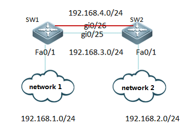
III. Configuration Tips
1. Assign IP address to SW1 and SW2
2. Configure Floating Static Routes with higheradministrator distance than the route it backs up
IV. ConfigurationSteps
1. Assign IP address to SW1
Ruijie>enable
Ruijie#configureterminal
Ruijie(config)#interfacefastethernet 0/1
Ruijie(config-if-FastEthernet0/1)#no switchport
Ruijie(config-if-FastEthernet0/1)#ip address 192.168.1.254 255.255.255.0
Ruijie(config-if-FastEthernet0/1)#interface GigabitEthernet 0/26
Ruijie(config-if-GigabitEthernet0/26)#ip address 192.168.4.1 255.255.255.0
Ruijie(config-if-GigabitEthernet0/26)#interface GigabitEthernet 0/25
Ruijie(config-if-GigabitEthernet0/25)#ip address 192.168.3.1 255.255.255.0
Ruijie(config-if-GigabitEthernet0/25)#exit
2. Assign IPaddress to SW2
Ruijie>enable
Ruijie#configureterminal
Ruijie(config)#interfacefastethernet 0/1
Ruijie(config-if-FastEthernet0/1)#ip address 192.168.2.254 255.255.255.0
Ruijie(config-if-FastEthernet0/1)#interface GigabitEthernet 0/26
Ruijie(config-if-GigabitEthernet0/26)#no switchport
Ruijie(config-if-GigabitEthernet0/26)#ip address 192.168.4.2 255.255.255.0
Ruijie(config-if-GigabitEthernet0/26)#interface GigabitEthernet 0/25
Ruijie(config-if-GigabitEthernet0/25)#no switchport
Ruijie(config-if-GigabitEthernet0/25)#ip address 192.168.3.2 255.255.255.0
Ruijie(config-if-GigabitEthernet0/25)#exit
3. ConfigureStatic Routes on SW1
Note:
1. When youconfigure static routes , there're two ways to specify next hop.You can specifyan IP address ,or you can specify a local outgoing interface.
2. We suggest youto use IP address as next hop
Ruijie(config)#iproute 192.168.2.0 255.255.255.0 192.168.3.2 ---->configure staticroutes to destination subnet 192.168.2.0/24 and nexthop is 192.168.3.2
Ruijie(config)#iproute 192.168.2.0 255.255.255.0 192.168.4.2 10 ---->configure floatingstatic routes to destination subnet 192.168.2.0/24 with administrtor distance10 and nexthop is 192.168.4.2 (by default , the administrator distance is 1.Thesmaller the number , the more likely the route will be installed in the iproute table)
4. ConfigureStatic Routes on SW2
Ruijie(config)#iproute 192.168.1.0 255.255.255.0 192.168.3.1 ---->configure staticroutes to destination subnet 192.168.1.0/24 and nexthop is 192.168.3.1
Ruijie(config)#iproute 192.168.1.0 255.255.255.0 192.168.4.1 10 ---->configure floatingstatic routes to destination subnet 192.168.1.0/24 with administrtor distance10 and nexthop is 192.168.4.1 (by default , the administrator distance is 1.Thesmaller the number , the more likely the route will be installed in the iproute table)
Ruijie(config)#end
Ruijie#write ---->confirm and save
V. Verification
1. This example displays the ip route table on SW1 whenport G0/25 comes up
SW1:
Ruijie#showip route
Codes: C - connected, S - static, R - RIP, B - BGP
O - OSPF, IA - OSPF inter area
N1 - OSPF NSSA external type 1, N2 - OSPF NSSA external type 2
E1 - OSPF external type 1, E2 - OSPF external type 2
i - IS-IS, su - IS-IS summary, L1 - IS-IS level-1, L2 - IS-IS level-2
ia - IS-IS inter area, * - candidate default
Gatewayof last resort is no set
S 192.168.2.0/24 [1/0] via 192.168.3.2
C 192.168.4.0/24 is directly connected, GigabitEthernet 0/26
C 192.168.4.1/32 is local host.
C 192.168.3.0/24 is directly connected, GigabitEthernet 0/25
C 192.168.3.1/32 is local host.
C 192.168.1.0/24 is directly connected, FastEthernet 0/1
C 192.168.1.1/32 is local host.
2. This example displays the ip route table on SW1after removing the cable on port G0/25. The floating route has been installedin ip route table.
SW1:
Ruijie#shoip route
Codes: C - connected, S - static, R - RIP, B - BGP
O - OSPF, IA - OSPF inter area
N1 - OSPF NSSA external type 1, N2 - OSPF NSSA external type 2
E1 - OSPF external type 1, E2 - OSPF external type 2
i - IS-IS, su - IS-IS summary, L1 - IS-IS level-1, L2 - IS-IS level-2
ia - IS-IS inter area, * - candidate default
Gatewayof last resort is no set
S 192.168.2.0/24 [10/0] via 192.168.4.2
C 192.168.4.0/24 is directly connected, GigabitEthernet 0/26
C 192.168.4.1/32 is local host.
C 192.168.1.0/24 is directly connected, FastEthernet 0/1
C 192.168.1.1/32 is local host.
2.9.3.2 RIP
Overview
The RIP (RoutingInformation Protocol) is a relatively old routing protocol, which is widelyused in small or homogeneous networks. The RIP uses the distance-vectoralgorithm, and so is a distance-vector protocol. The RIPv1 is defined in RFC1058 and the RIPv2 is defined in RFC 2453. Ruijie RGOS supports both twoversions.
The RIP exchanges the routing information by using theUDP packets, with the UDP port number to be 520. Usually, RIPv1 packets arebroadcast packets, while RIPv2 packetsare multicast packets with the multicastaddress of 224.0.0.9. The RIP sends the update packet at the interval of 30seconds. If the device has not received the route update packets from the peerwithin 180 seconds, it will mark all the routes from that device unreachable.After that, the device will delete these routes from its routing table if itstill has not received any update packets from the peer within 120s.
The RIP measures the distanceto the destination in hop,known as route metric. As specified in the RIP, Zero hop exists when the routerdirectly connects to the network. One hop exists when the router connects tothe network through one device and so on. Up to 16 hops are supported in anetwork.
Note: We suggest you to build your networkwith OSPF rathan than RIP if possible.
I. Requirements
Configure the switch with RIP and ensurethat users in network 1 can communicate with users in network 2
II. Network Topology
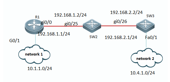
III. Configuration Tips
1. Assign IP address to R1, SW2 and SW3.
2. Initialize RIP process and define thecorresponding interface on which RIP runs
IV. ConfigurationSteps
1. Assign IP addresses to R1, SW2 and SW3
Ruijie(config)#hostnameR1
R1(config)#interfacegigabitEthernet 0/0
R1(config-GigabitEthernet0/0)#ip address 192.168.1.1 255.255.255.0
R1(config-GigabitEthernet0/0)#exit
R1(config)#interfacegigabitEthernet 0/1
R1(config-GigabitEthernet0/1)#ip address 10.1.1.1 255.255.255.0
R1(config-GigabitEthernet0/1)#exit
Ruijie(config)#hostnameSW2
SW2(config)#interfacegigabitEthernet 0/25
SW2(config-if-GigabitEthernet0/25)#no switchport
SW2(config-if-GigabitEthernet0/25)#ip address 192.168.1.2 255.255.255.0
SW2(config-if-GigabitEthernet0/25)#exit
SW2(config)#interfacegigabitEthernet 0/26
SW2(config-if-GigabitEthernet0/26)#no switchport
SW2(config-if-GigabitEthernet0/26)#ip address 192.168.2.1 255.255.255.0
SW2(config-if-GigabitEthernet0/26)#exit
Ruijie(config)#hostnameSW3
SW3(config)#interfacegigabitEthernet 0/26
SW3(config-if-GigabitEthernet0/26)#no switchport
SW3(config-if-GigabitEthernet0/26)#ip address 10.4.1.1 255.255.255.0
SW3(config-if-GigabitEthernet0/26)#exit
SW3(config)#interfacefastEthernet 0/1
SW3(config-if-FastEthernet0/1)#no switchport
SW3(config-if-FastEthernet0/1)#ip address 192.168.2.2 255.255.255.0
SW3(config-if-FastEthernet0/1)#exit
2. Initialize RIP process and define the thecorresponding interface on which RIP runs
Note:
1. There're two RIP version : version 1 andversion 2. RIPv2 utilizes multicast to propagate routing update instead ofbroadcast which RIPv1 utilizes.In addistion , RIPv2 routing update carriesrouting mask information which RIPv1 doesn't carry.
2. When you enter "network"command in RIP configuration mode to define interfaces on RIP , you can only define classful ip address range ,such as10.0.0.0/8 or 172.16.0.0/16 ,and all interfaces belongs to the classful ipaddress range are defined on RIP.
3)By default,RIP auto summary is enabled andthe switch auto summarizes subprefixes when crossing classful network boundaries.We suggest youto disable auto summary and summarize routes manually in case that switchlearns incorrect routes when crossing incontinuous network.
R1(config)#routerrip
R1(config-router)#version2 ----->specify RIP version 2
R1(config-router)#noauto-summary ----->disable auto-summary
R1(config-router)#network192.168.1.0 ----->define ip address range 192.168.1.0 on RIP
R1(config-router)#network10.0.0.0
R1(config-router)#exit
SW2(config)#routerrip
SW2(config-router)#version2
SW2(config-router)#noauto-summary
SW2(config-router)#network192.168.1.0
SW2(config-router)#network192.168.2.0
SW2(config-router)#exit
SW3(config)#routerrip
SW3(config-router)#version2
SW3(config-router)#noauto-summary
SW3(config-router)#network192.168.2.0
SW3(config-router)#network10.0.0.0
SW3(config-router)#exit
V. Verification
This example shows how to display IP route table andRIP routing information is propagated all over the network correctly
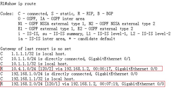
2.9.3.3 OSPF
Overview
OSPF (Open Shortest Path First) is an internal gatewayrouting protocol based on link status developed by the IETF OSPF work group.OSPF, a routing protocol specific for IP, directly runs on the IPlayer. Itsprotocol number is 89. OSPF packets are exchanged in multicast form using themulticast address 224.0.0.5 (for all OSPF routers) and 224.0.0.6 (for specifiedrouters).
Note: we recommend that you can give priorityto OSPF to build your network
I. Requirements
Use OSFP to build your network and every node in thenetwork can communicate with each other.
II. Network Topology
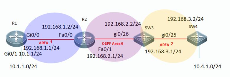
III. Configuration Tips
1. Assign IP addresss to R1, R2 SW3 and SW4
2. Initialize OSPF process on all devicesand define corresponding interfaces which OSPF runs and define the area ID forthose interfaces.
3. (Optional) Modify network type oninterfaces that have OSPF enabled
IV. ConfigurationSteps
1. Assign IP addresss to R1, R2 SW3 and SW4
Ruijie(config)#hostnameR1
R1(config)#interfacegigabitEthernet 0/0
R1(config-GigabitEthernet0/0)#ip address 192.168.1.1 255.255.255.0
R1(config-GigabitEthernet0/0)#exit
R1(config)#interfacegigabitEthernet 0/1
R1(config-GigabitEthernet0/1)#ip address 10.1.1.1 255.255.255.0
R1(config-GigabitEthernet0/1)#exit
R1(config)#interfaceloopback 0 ----->configureIP address of Loopback 0 as OSPF Router-id
R1(config-if-Loopback0)#ip address 1.1.1.1 255.255.255.255
R1(config-if-Loopback0)#exit
Ruijie(config)#hostnameR2
R2(config)#interfacefastEthernet 0/0
R2(config-if-FastEthernet0/0)#ip address 192.168.1.2 255.255.255.0
R2(config-if-FastEthernet0/0)#exit
R2(config)#interfacefastEthernet 0/1
R2(config-if-FastEthernet0/1)#ip address 192.168.2.1 255.255.255.0
R2(config-if-FastEthernet0/1)#exit
R2(config)#interfaceloopback 0
R2(config-if-Loopback0)#ip address 2.2.2.2 255.255.255.255
R2(config-if-Loopback0)#exit
Ruijie(config)#hostnameSW3
SW3(config)#interfaceGigabitEthernet 0/26
SW3(config-if-GigabitEthernet0/26)#no switchport
SW3(config-if-GigabitEthernet0/26)#ip address 192.168.2.2 255.255.255.0
SW3(config-if-GigabitEthernet0/26)#exit
SW3(config)#interfaceGigabitEthernet 0/25
SW3(config-if-GigabitEthernet0/25)#no switchport
SW3(config-if-GigabitEthernet0/25)#ip address 192.168.3.1 255.255.255.0
SW3(config-if-GigabitEthernet0/25)#exit
SW3(config)#interfaceloopback 0
SW3(config-if-Loopback0)#ip address 3.3.3.3 255.255.255.255
SW3(config-if-Loopback0)#exit
Ruijie(config)#hostnameSW4
SW4(config)#interfacegigabitEthernet 0/25
SW4(config-if-GigabitEthernet0/25)#no switchport
SW4(config-if-GigabitEthernet0/25)#ip address 192.168.3.2 255.255.255.0
SW4(config-if-GigabitEthernet0/25)#exit
SW4(config)#interfacegigabitEthernet 0/1
SW4(config-if-GigabitEthernet0/1)#no switchport
SW4(config-if-GigabitEthernet0/1)#ip address 10.4.1.1 255.255.255.0
SW4(config-if-GigabitEthernet0/1)#exit
SW4(config)#interfaceloopback 0
SW4(config-if-Loopback0)#ip address 4.4.4.4 255.255.255.255
SW4(config-if-Loopback0)#exit
2. Initialize OSPF process on all devicesand define corresponding interfaces which OSPF runs and define the area ID forthose interfaces.
Note:
1) OSPF doesn't propagate process ID toneighbor ,so process ID can be different in a OSPF area.
2)OSPF detects peer neighbor area ID inhello packet while establishing OSPF neighbor. OSPFarea ID of OSPF neighbor must match.
R1(config)#routerospf 1 ----->enableOSPF globally , and process ID is 1
R1(config-router)#network192.168.1.1 0.0.0.0 area 1 ----->OSPF area 1 runs on interface192.168.1.1
R1(config-router)#network10.1.1.1 0.0.0.0 area 1
R1(config-router)#exit
R2(config)#routerospf 1
R2(config-router)#network192.168.1.2 0.0.0.0 area 1
R2(config-router)#network192.168.2.1 0.0.0.0 area 0
R2(config-router)#exit
SW3(config)#routerospf 1
SW3(config-router)#network192.168.2.2 0.0.0.0 area 0
SW3(config-router)#network192.168.3.1 0.0.0.0 area 2
SW3(config-router)#exit
SW4(config)#routerospf 1
SW4(config-router)#network192.168.3.2 0.0.0.0 area 2
SW4(config-router)#network10.4.1.1 0.0.0.0 area 2
SW4(config-router)#exit
3. (Optional)Modify network type oninterfaces that have OSPF enabled
Note:By default ,OSPF interface network type is broadcast in Ethernet and it costs about 40seconds to elect DR/BDR . We recommend that you modify network type topoint-to-point type in Ethernet to accelerate OSPF neighbor convergence.
R2(config)#interfacefastEthernet 0/1
R2(config-if-FastEthernet0/1)#ip ospf network point-to-point ----->modify OSPFinterface network type to point-to-point (you must configure bothOSPF peers at the same time)
R2(config-if-FastEthernet0/1)#exit
SW3(config)#interfacefastEthernet 0/1
SW3(config-if-FastEthernet0/1)#ip ospf network point-to-point
SW3(config-if-FastEthernet0/1)#exit
V. Verification
1. How to display OSPF neighbor table
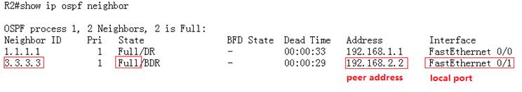
2. How to display IP route table
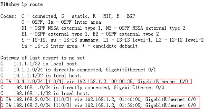
Redistribution
Overview
To support therouters to run multiple routing protocol processes, Ruijie product provides thefunction for redistributing the route information from one routing process toanother routing process .For example, you can redistribute the routes in theOSPF routing area to the RIP routing area, or those in the RIP routing area tothe OSPF routing area. Routes can be redistributed among all the IP routingprotocols.
I. Requirements
Redistribute static route into OSPFprocess.All nodes in OSPF area can communicate with nodes in 10.1.2.0/24
II. Network Topology

III. Configuration Tips
1. Assign IP address and initialize OSPFprocess
2. Configure a static route on SW1 pointingto subnet 10.1.2.0/24
3. Redistribute static route into OSPFprocess
IV. ConfigurationSteps
1. Assign IP addresss and initialize OSPFprocess
see Chapter OSPF----> Configuring basic OSPF
2. Configure a static route on SW1 pointingto subnet 10.1.2.0/24
SW1(config)#iproute 10.1.2.0 255.255.255.0 192.168.11.2
3. Redistribute static route into OSPF
Note:
1) This example shows the OSPF redistributioncommands:
SW1(config)#routerospf 1
SW1(config-router)#redistribute?
bgp Border Gateway Protocol (BGP)
connected Connected
ospf Open Shortest Path First (OSPF)
rip Routing Information Protocol (RIP)
static Static routes
2) There are 2 types of redistributing externalroutes --- type 1 and type 2. The caculation method for route metic of Type 1and Type 2 is different.
a. The metric of type 1 is the addition ofthe external cost and the internal cost used to reach that route. A type 1route is always preferred over a type 2 route for the same destination.
b. The metric of a type 2 route is alwaysthe external cost, irrespective of the interior cost to reach that route. Bydefault, the redistributed external routes is type 2
SW1(config)#routerospf 1
SW1(config-router)#redistributestatic metric-type ?
1 Set OSPF External Type 1 metrics
2 Set OSPF External Type 2 metrics
3) Only the routes that has been installedin IP route table can be redistribute into OSPF process.You can use "showip route" EXEC command to verify it.
4) You must add keyword "subnets" when you redistribute routes into OSPF ,otherwise only classful routes will be redistributed.
This example shows how to redistributestatic route into OSPF process.
SW1(config)#routerospf 1
SW1(config-router)#redistributestatic subnets ----->redistribute staticroutes
SW1(config-router)#exit
V. Verification
How to display IP route table and verify thereditributed routes
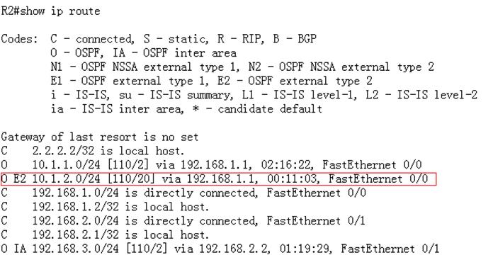
Summary
Overview
You can configureOSPF summary to reduce route numbers, decrease load of device resources.
Note: You can enable OSPF summary on ABR andASBR ONLY
I. Requirements
Configure OSPF summary to reduce routesnumber on SW1
II. Network Topology

III. Configuration Tips
You can configure OSPF summary on ABR(areaborder router) or ASBR(Autonomous System Border Router).
IV. ConfigurationSteps
1. Assign IP addresses and initial OSPFprocess
see Chapter OSPF----> Configuring basic OSPF
2. Redistribute static routes that pointingto subnet 10.1.2.0/24 into OSPF on SW1
see Chapter OSPF----> Redistribution
3. Configure OSPF inter-area summary
This example specifies one summary route tobe advertised by the ABR to other areas for all subnets on network 10.4.0.0/16
SW3(config)#routerospf 1
SW3(config-router)#area2 range 10.4.0.0 255.255.0.0 ----->summarised internal routes(2indicates the identifier of the area about which routes are to be summarized)
SW3(config-router)#exit
4. External routes summary
This example specifies one summary route tobe advertised by the ASBR to other areas for all subnets on network 10.1.0.0/16
SW1(config)#routerospf 1
SW1(config-router)#summary-address10.1.0.0 255.255.0.0 ----->summarise external routes
SW1(config-router)#exi
V. Verification
How to display IP route table and verifysummarised routes
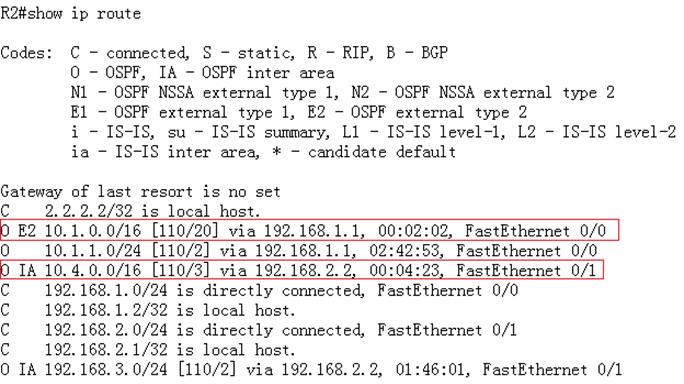
Stub area
Overview
If an area is the OSPF leaf area (not a backbone areaor Transit area) and no routes are imported on the devices in the area,configure the area to a STUB area. The STUB area can learn only three kinds ofroutes: inter-area routes, ABR advertised default routes, and routes from otherareas. Without a large number of external routes, the routing tables of thedevices in the STUB area are small, which reduce device resources. The devicesin the STUB area are medium and low end devices.
Routers in Stubarea don't propagate class 4 and class 5 LSA(external routes), so this actionreduces the size of LSA database and route table . ABR of stub area alsocreates a class 3 inter-area (O *IA) default route automatically to ensurenodes in stub area can communicate with nodes in other areas.
I. Requirements
1. Configure area 2 as a Stub Area to filterclass 4 and class 5 LSA.
2. Configure area 2 as a Totally Stub Areato filter class3, 4 and 5 LSA.
II. Network Topology
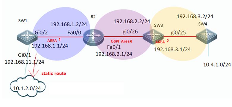
III. Configuration Tips
1. ABR of a Stub area filters class 4 and 5LSA and creates a class 3 default route
2. ABR of a Totally Stub area filters class3,4 and 5 LSA and creates a class 3 default route .
3. You cannot redistribute routes into astub area.
IV. ConfigurationSteps
1. Configuring Stub area
1.1. Assign IP addresses and configureinitial OSPF
see Chapter OSPF----> Configuring basic OSPF
1.2. Configure a static route on SW1 andredistribute the static route into OSPF
see Chapter OSPF----> Redistribution
1.3. Configuring area 2 as Stub area
Note:
1) You must configure all routes in Stubarea with the "stub" command
2) You cannot configure area 0 as Stubarea.
SW3(config)#routerospf 1
SW3(config-router)#area2 stub ----->specify SW3 in stub area 2
SW3(config-router)#exit
R4(config)#routerospf 1
R4(config-router)#area2 stub
R4(config-router)#exit
2. Configuring Totally stub area
2.1. Assign IP addresses and configure basicOSPF parameters
see Chapter OSPF----> Configuring basic OSPF
2.2. Configuring a static route on SW1 andredistribute static route into OSPF
see Chapter OSPF----> Redistribution
2.3. Configuring area 2 as Totally Stub area
Note:You mustconfigure all routes in Totally Stub area with the"stub no-summary" command
SW3(config)#routerospf 1
SW3(config-router)#area2 stub no-summary ----->specify SW3 in Totally Stub area 2
SW3(config-router)#exit
R4(config)#routerospf 1
R4(config-router)#area2 stub
R4(config-router)#exit
V. Verification
1. In a stub area, display IP route tableand verify that no external route is installed and ABR creates a class-3default route.
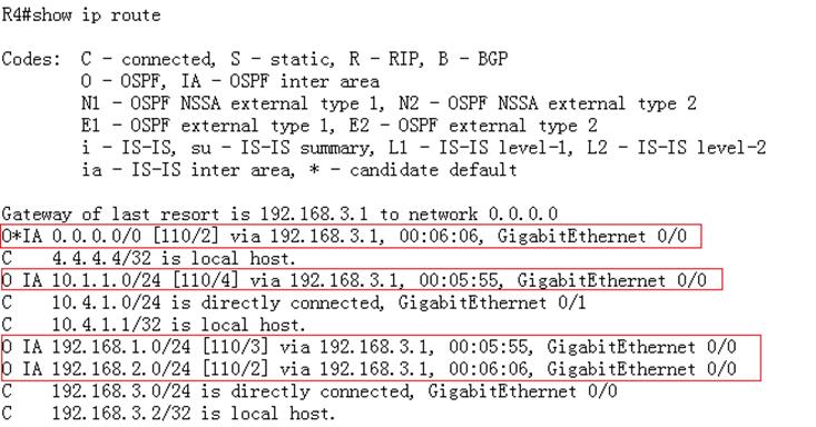
2. In a Totally stub area , display IP routetable and verify that no inter-area route and external route are intalled andABR creates a class-3 default route.
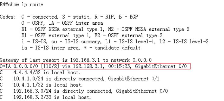
NSSA area
Overview
Routers in NSSA (not so stub area) don't propagateclass 4 and class 5 LSA, so this action reduces the size of LSA database androute table. In addition, you can redistribute routesinto a NSSA.
I. Requirements
1. Configure area 2 as a NSSA to filterclass 4 and 5 LSA ,then redistribute external static routes into NSSA.
2. Configure area 2 as a Totally Stub Areato filter class 3 , 4 and 5 LSA , then redistribute external static routes intoTotally NSSA Area.
II. Network Topology
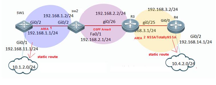
III. Configuration Tips
1. ABR of a NSSA filters class 4 and 5 LSA,,butdoesn't creates a class 3 default route
2. ABR of a Totally NSSA filters class 3,4and 5 LSA and creates a class 3 default route .
3. You can redistribute routes into a NSSAor totally NSSA.
IV. ConfigurationSteps
1. Configuring NSSA area
1.1. Assign IP addresss and configure basicOSPF parameters
see Chapter OSPF----> Configuring basic OSPF
1.2 Configure static routes on SW1 and R4,then redistribute static routes into OSPF
see Chapter OSPF----> Redistribution
1.3 Configure Area 2 as NSSA
Note:
1) You must configure all routes in NSSAwith the "nssa" command
2) You cannot configure area 0 as Stubarea.
R3(config)#routerospf 1
R3(config-router)#area2 nssa ---->specify R3 in NSSA area 2
R3(config-router)#exit
R4(config)#routerospf 1
R4(config-router)#area2 nssa
R4(config-router)#exit
2. Configuring Totally NSSA area
2.1 Assign IP addresss and configure basicOSPF parameters
see Chapter OSPF----> Configuring basic OSPF
2.2 Configure static routes on SW1 and R4,then redistribute static routes into OSPF
see Chapter OSPF----> Redistribution
2.3 Configure Area 2 as Totally NSSA area
Note:
You must configure all routes in totallyNSSA with the "nssa no-summary"command
R3(config)#routerospf 1
R3(config-router)#area2 nssa no-summary -----> specify R3 in totally NSSA area 2
R3(config-router)#exit
R4(config)#routerospf 1s
R4(config-router)#area2 nssa
R4(config-router)#exit
V. Verification
1. In NSSA , display IP route table andverify that no external route (O E1 and O E2)is installed and ABR doesn'tcreates a class-3 default route.In addition ,you can redistribute routes intoNSSA in the format (O N1 and O N2)
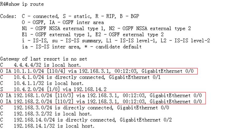
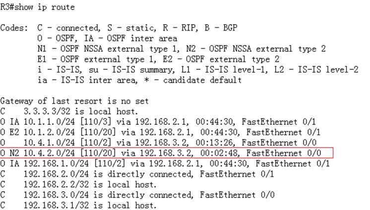
2. In totally NSSA , display IP route tableand verify that no external route (O E1 and O E2) ,or inter-area route(O IA)areinstalled and ABR creates a class-3 default route.In addition ,you canredistribute routes into totally NSSA in the format (O N1 and O N2)
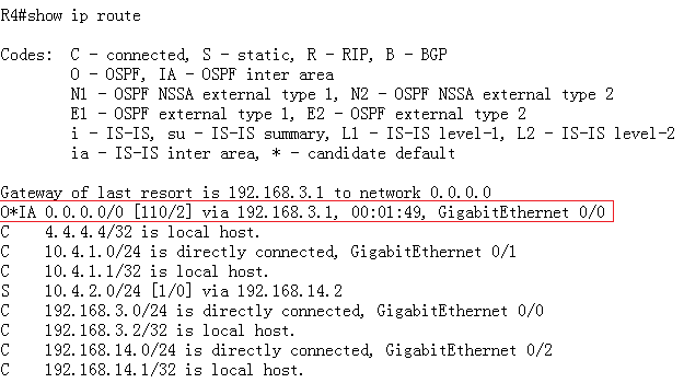

2.9.3.4 BGP
2.9.3.4.1 Basic iBGP Configuration
Scenario
External gateway protocols such as the BGPare mainly applied on large-scale networks for the transmission oflarge-quantity IGP routes. In addition, the BGP flexibly provides someproperties for routing control. Major scenarios include networks of telecomoperators and secondary or tertiary ISPs, provincial backbone networks offinancial industries, and municipal e-government networks. Generally, the BGPis not independently deployed in these scenarios, but is deployed together withthe MPLS in BGP + MPLS VPN networking mode. The iBGP is a routing protocol usedin BGP connection setup between devices connected to the same AS.
I. NetworkingRequirements
1. Switch 1, Switch 2,and Switch 3 are switches of AS123. Switch 1 and Switch 2 are configured asiBGP neighbors, and Switch 2 and Switch 3 are configured as iBGP neighbors.
2. The route informationis delivered to the neighbor over the iBGP.
II. Network Topology
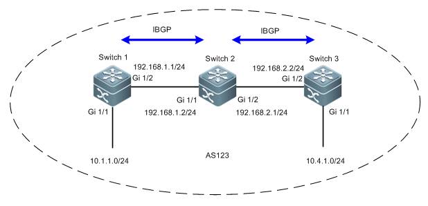
III. ConfigurationTips
1. Determine the sourceaddress for BGP neighbor update.
Note:
1) If the eBGP neighbor is on the edge of theAS, it is recommended that adirect-connectioninterface is used as the update source address. In thiscase, you do not have to setup an IGP route between the update sourceaddresses.
2) If the iBGP neighbor is inside the AS, it isrecommended that a loopback address be used as the update source address. A loopback address is morereliable (which will not cause BGP neighbor turbulence at a physical circuitfailure). Generally, IGP routes between update source addresses are deployedwithin the AS.
2. The iBGP features horizontal segregation.That is, the route learned from one iBGP neighbor are not delivered to anotheriBGP neighbor (but will be delivered to an eBGP neighbor).
IV. ConfigurationSteps
Note:
Rename the devices asSW1, SW2, and SW3 according to the preceding topology and perform the followingconfigurations:
1. Configure the basicIP addresses for the devices on the network.
Ruijie(config)#hostname SW1
SW1(config)#interface gigabitEthernet 1/2
SW1(config-if-GigabitEthernet 1/2)#no switchport
SW1(config-if-GigabitEthernet 1/2)#ip address 192.168.1.1255.255.255.0
SW1(config-if-GigabitEthernet 1/2)#exit
SW1(config)#interface gigabitEthernet 1/1
SW1(config-if-GigabitEthernet 1/1)#no switchport
SW1(config-if-GigabitEthernet 1/1)#ip address 10.1.1.1255.255.255.0
SW1(config-if-GigabitEthernet 1/1)#exit
SW1(config)#interface loopback 0
SW1(config-if-Loopback 0)#ip address 1.1.1.1 255.255.255.255
SW1(config-if-Loopback 0)#exit
Ruijie(config)#hostname SW2
SW2(config)#interface gigabitEthernet 1/1
SW2(config-if-GigabitEthernet 1/1)#no switchport
SW2(config-if-GigabitEthernet 1/1)#ip address 192.168.1.2255.255.255.0
SW2(config-if-GigabitEthernet 1/1)#exit
SW2(config)#interface gigabitEthernet 1/2
SW2(config-if-GigabitEthernet 1/2)#no switchport
SW2(config-if-GigabitEthernet 1/2)#ip address 192.168.2.1255.255.255.0
SW2(config-if-GigabitEthernet 1/2)#exit
SW2(config)#interface loopback 0
SW2(config-if-Loopback 0)#ip address 2.2.2.2 255.255.255.255
SW2(config-if-Loopback 0)#exit
Ruijie(config)#hostname SW3
SW3(config)#interface gigabitEthernet 1/1
SW3(config-if-GigabitEthernet 1/1)#no switchport
SW3(config-if-GigabitEthernet 1/1)#ip address 10.4.1.1255.255.255.0
SW3(config-if-GigabitEthernet 1/1)#exit
SW3(config)#interface gigabitEthernet 1/2
SW3(config-if-GigabitEthernet 1/2)#no switchport
SW3(config-if-GigabitEthernet 1/2)#ip address 192.168.2.2255.255.255.0
SW3(config-if-GigabitEthernet 1/2)#exit
SW3(config)#interface loopback 0
SW3(config-if-Loopback 0)#ip address 3.3.3.3 255.255.255.255
SW3(config-if-Loopback 0)#exit
2. Enable OSPF for theentire network and set to notify the corresponding interface to the OSPFprocess so that the loopback interfaces on the entire network are reachable.
SW1(config)#router ospf 1
SW1(config-router)#network 192.168.1.1 0.0.0.255 area 0
SW1(config-router)#network 1.1.1.1 0.0.0.0 area 0
SW1(config-router)#exit
SW2(config)#router ospf 1
SW2(config-router)#network 192.168.1.2 0.0.0.255 area 0
SW2(config-router)#network 2.2.2.2 0.0.0.0 area 0
SW2(config-router)#exit
SW3(config)#router ospf 1
SW3(config-router)#network 192.168.2.2 0.0.0.255 area 0
SW3(config-router)#network 3.3.3.3 0.0.0.0 area 0
SW3(config-router)#exit
3. Configure iBGPneighbors.
Note:
1) If the BGP neighbor is of the same AS ID,it is created as an iBGP neighbor. If the BGP neighbor is of a different AS ID,it is created as an eBGP neighbor.
SW1(config)#router bgp 123
SW1(config-router)#neighbor 2.2.2.2 remote-as 123
SW1(config-router)#neighbor 2.2.2.2 update-source loopback0
SW1(config-router)#exit
SW2(config)#router bgp 123
SW2(config-router)#neighbor 1.1.1.1 remote-as 123
SW2(config-router)#neighbor 1.1.1.1 update-source loopback 0
SW2(config-router)#neighbor 3.3.3.3 remote-as 123
SW2(config-router)#neighbor 3.3.3.3 update-source loopback 0
SW2(config-router)#exit
SW3(config)#router bgp 123
SW3(config-router)#neighbor 2.2.2.2 remote-as 123
SW3(config-router)#neighbor 2.2.2.2 update-source loopback 0
SW3(config-router)#exit
4. Notify the BGPprocess about the route information.
Note:
Run the network command to notify theBGP process about the routes in the BGP. The command does not enable BGP onthese interfaces, which is different from the rip and ospfcommands. The routes conveyed in the network command must exist locally (that is, can be returned by the showip route command) and its mask is consistent with the mask parameter. Otherwise, the BGP process is not notified.
SW1(config)#router bgp 123
SW1(config-router)#network 10.1.1.0 mask 255.255.255.0
SW1(config-router)#exit
SW3(config)#router bgp 123
SW3(config-router)#network 10.4.1.0 mask 255.255.255.0
SW2#show ip route
Codes: C - Connected, L - Local, S - Static
R - RIP, O - OSPF, B - BGP, I - IS-IS, V -Overflow route
N1 - OSPF NSSA external type 1, N2 - OSPFNSSA external type 2
E1 - OSPF external type 1, E2 - OSPFexternal type 2
SU - IS-IS summary, L1 - IS-IS level-1, L2- IS-IS level-2
IA - Inter area, * - candidate default
Gateway of last resort is no set
O 1.1.1.1/32 [110/1] via 192.168.2.1, 16:07:50,GigabitEthernet 1/1
C 2.2.2.2/32 is local host.
O 3.3.3.3/32 [110/1] via 192.168.2.2, 16:07:50,GigabitEthernet 1/2
B 10.1.1.0/24 [200/0] via 1.1.1.1, 00:10:12
B 10.4.1.0/24 [200/0] via 3.3.3.3, 00:08:44
C 192.168.1.0/24 is directly connected,GigabitEthernet 1/1
C 192.168.1.2/32 is local host.
C 192.168.2.0/24 is directly connected,GigabitEthernet 1/2
C 192.168.2.1/32 is local host.
V. Verification
1. Check whether the BGPneighboring relationship is established between routers and the neighborstatus. If the BGP neighboring relationship can be established properly and thestatus is Established, the iBGP runs properly.
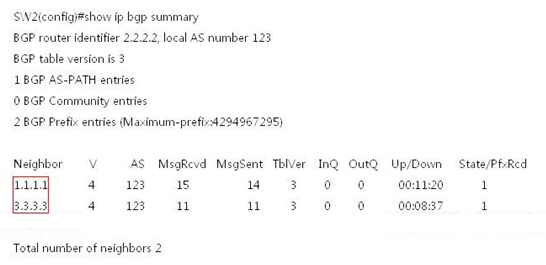
2. Check the route of theiBGP neighbor router. If the route delivered by the neighbor can be learned,the iBGP configuration is correct.
Basic eBGP Configuration
SW2#show ip route
Codes: C - Connected, L - Local, S - Static
R - RIP, O - OSPF, B - BGP, I - IS-IS, V -Overflow route
N1 - OSPF NSSA external type 1, N2 - OSPFNSSA external type 2
E1 - OSPF external type 1, E2 - OSPFexternal type 2
SU - IS-IS summary, L1 - IS-IS level-1, L2- IS-IS level-2
IA - Inter area, * - candidate default
Gateway of last resort is no set
O 1.1.1.1/32 [110/1] via 192.168.2.1, 16:07:50,GigabitEthernet 1/1
C 2.2.2.2/32 is local host.
O 3.3.3.3/32 [110/1] via 192.168.2.2, 16:07:50,GigabitEthernet 1/2
B 10.1.1.0/24 [200/0] via 1.1.1.1, 00:10:12
B 10.4.1.0/24 [200/0] via 3.3.3.3, 00:08:44
C 192.168.1.0/24 is directly connected,GigabitEthernet 1/1
C 192.168.1.2/32 is local host.
C 192.168.2.0/24 is directly connected,GigabitEthernet 1/2
C 192.168.2.1/32 is local host.
2.9.3.4.2 Basic eBGP Configuration
Scenario
External gatewayprotocols such as the BGP are mainly applied on large-scale networks for thetransmission of large-quantity IGP routes. In addition, the BGP flexiblyprovides some properties for routing control. Major scenarios include networksof telecom operators and secondary or tertiary ISPs, provincial backbonenetworks of financial industries, and municipal e-government networks.Generally, the BGP is not independently deployed in these scenarios, but isdeployed together with the MPLS in BGP + MPLS VPN networking mode. The eBGP isa routing protocol used in BGP connection setup between devices connected todifferent ASs.
I. NetworkingRequirements
1. Set Switch 1 to AS 1,Switch 2 to AS 2, and establish eBGPP neighboring relationships between Switch1 and Switch 2.
2. The route informationis delivered to the neighbor over the eBGP.
II. Network Topology
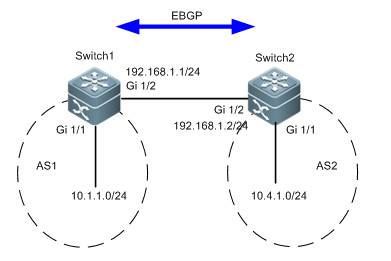
III. Configuration Tips
1. Configure the basic IPaddresses.
2. Configure eBGPneighbors.
3. Notify the BGP processabout the route information.
IV. ConfigurationSteps
Note:
Rename the devices as SW1and SW2 according to the preceding topology and perform the following configurations:
1. Configure the basicIP addresses.
Ruijie(config)#hostname SW1
SW1(config)#interface gigabitEthernet 1/2
SW1(config-if-GigabitEthernet 1/2)#no switchport
SW1(config-if-GigabitEthernet 1/2)#ip address 192.168.1.1255.255.255.0
SW1(config-if-GigabitEthernet 1/2)#exit
SW1(config)#interface gigabitEthernet 1/1
SW1(config-if-GigabitEthernet 1/1)#no switchport
SW1(config-if-GigabitEthernet 1/1)#ip address 10.1.1.1255.255.255.0
SW1(config-if-GigabitEthernet 1/1)#exit
Ruijie(config)#hostname SW2
SW2(config)#interface gigabitEthernet 1/2
SW2(config-if-GigabitEthernet 1/2)#no switchport
SW2(config-if-GigabitEthernet 1/2)#ip address 192.168.1.2255.255.255.0
SW2(config-if-GigabitEthernet 1/2)#exit
SW2(config)#interface gigabitEthernet 1/1
SW2(config-if-GigabitEthernet 1/1)#no switchport
SW2(config-if-GigabitEthernet 1/1)#ip address 10.4.1.1255.255.255.0
SW2(config-if-GigabitEthernet 1/1)#exit
2. Configure eBGPneighbors.
Note:
1) If the BGP neighbor is of the same AS ID,it is created as an iBGP neighbor. If the BGP neighbor is of a different AS ID,it is created as an eBGP neighbor.
SW1(config)#router bgp 1
SW1(config-router)#neighbor 192.168.1.2 remote-as 2
SW1(config-router)#exit
SW2(config)#router bgp 2
SW2(config-router)#neighbor 192.168.1.1 remote-as 1
SW2(config-router)#exit
3. Notify the BGPprocess about the route information.
SW1(config)#router bgp 1
SW1(config-router)#network 10.1.1.0 mask 255.255.255.0
SW1(config-router)#exit
SW2(config)#router bgp 2
SW2(config-router)#network 10.4.1.0 mask 255.255.255.0
SW2(config-router)#exit
Note:
Run the network command to notify theBGP process about the routes in the BGP. The command does not enable BGP onthese interfaces, which is different from the rip and ospfcommands. The routes conveyed in the network command must exist locally (that is, can be returned by the showip route command) and its mask is consistent with the mask parameter. Otherwise, the BGP process is not notified.
V. Verification
1. Check whether the BGPneighboring relationship is established between routers and the neighborstatus. If the BGP neighboring relationship can be established properly and thestatus is Established, the eBGP runs properly.
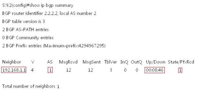
2. Check the route of theeBGP neighbor router. If the route delivered by the neighbor can be learned,the eBGP configuration is correct.
SW2#show ip route
Codes: C - Connected, L - Local, S - Static
R - RIP, O - OSPF, B - BGP, I - IS-IS, V -Overflow route
N1 - OSPF NSSA external type 1, N2 - OSPFNSSA external type 2
E1 - OSPF external type 1, E2 - OSPFexternal type 2
SU - IS-IS summary, L1 - IS-IS level-1, L2- IS-IS level-2
IA - Inter area, * - candidate default
Gateway of last resort is no set
C 2.2.2.2/32 is local host.
B 10.1.1.0/24 [20/0] via 192.168.1.1, 00:09:34
C 10.4.1.0/24 is directly connected,GigabitEthernet 1/1
C 10.4.1.1/32 is local host.
C 192.168.1.0/24 is directly connected,GigabitEthernet 1/2
C 192.168.1.2/32 is local host.
2.9.3.4.3 Route Reflector
Scenario
A route reflector ismainly used to solve the horizontal route segregation issue in side an iBGP.(As a switch does not deliver the route received from an iBGP neighbor toanother iBGP neighbor, routes are not comprehensively learned and blackholesmay result in.) To solve the horizontal segregation issue for the iBGP, iBGPneighbor full mesh must be adopted. However, if a large number of iBGPneighbors are configured in full mesh, the number of iBGP neighbor pairs willincrease exponentially. Maintenance of these neighboring information and routeinformation will be very complicated and consume a large volume of deviceresources. To solve the issue, route reflectors are used. With routereflectors, the number of iBGP peer connections in an AS is reduced. A routereflector is similar to the DR and BDR of the OSPF in a broadcastingenvironment. It can be deployed to reduce resource consumption in an iBGPnetwork environment with a large number of neighbors in full mesh or to aid therepeated configuration of a large number of iBGP neighbors.
Function Overview
To speed up routeinformation convergence, generally, all BGP speakers in an AS are configured ina full mesh, that is, every two BGP speakers are configured into a neighboringpair. When the AS has a large number of GBP speakers, the BGP speaker resourceconsumption increases greatly, as well as the configuration task volume andcomplexity for the network administrator. The network scaling performance isundermined.
A route reflector caneffectively reduce the number of iBGP peer connections in an autonomous system(AS). You can set an BGP speaker as a route reflector and classify all iBGPpeers in the AS into route reflector clients and non-clients. The rules forimplementing the route reflector in an AS include the following:
1. Configure the routereflector and specify its clients. The route reflector and its clients form agroup. Connection is established between the route reflector and its clients.
2. A route reflectorclient in one group does not establish connection with BGP speakers not in thegroup.
3. Within the AS, set upfull-mesh connections between non-client iBGP peers. An pair of non-client iBGPpeers can be two route reflectors in one group, a route reflector in one groupand a BGP speaker not configured with the route reflector function, and a routereflector in one group and a route reflector in another group.
The route received by aroute reflector is processed as follows:
1. The route updatereceived from an eBGP speaker is sent to all clients and non-clients.
2. The route updatereceived from a client is sent to all other clients and all clients.
3. The route updatereceived from an iBGP non-client and is sent to all clients.
I. NetworkingRequirements
As shown in the followingtopology, due to the horizontal segregation feature of the iBGP, SW1 and SW3cannot learn BGP routes from each other. The route reflector must be configuredto solve the issue.
II. Network Topology
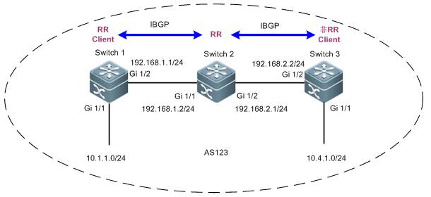
III. ConfigurationTips
1. Configure the IPaddresses of the routers or switches on the entire network and perform basiciBGP configurations.
2. Configure the routereflector function.
IV. ConfigurationSteps
1. Configure the IPaddresses of the routers on the entire network and perform basic iBGPconfigurations.
See the section"Basic iBGP Configuration."
2. Configure the routereflector function.
Set SW2 as the routereflector and specify R1 as the route reflector client.
SW2(config)#router bgp 123
SW2(config-router)#neighbor 1.1.1.1 route-reflector-client
SW2(config-router)#exit
Note:
1. When a switch isconfigured as a route reflector client, its BGP neighboring relationship nolonger exists.
2. A route reflector needs to propagateroutes, therefore, it must be provided with chances to learn corresponding iBGProutes.
3. A non-client can reflect routes to aclient and vice versa. Clients can reflect routes to clients. However, routes learned from a non-client cannotbe reflected to another non-client.
V. Verification
Check the routes on theentire network. If SW1 can learn the routes of SW3 and vice versa, the routereflector function is configured correctly.
SW1#show ip route
Codes: C - Connected, L - Local, S - Static
R - RIP, O - OSPF, B - BGP, I - IS-IS, V -Overflow route
N1 - OSPF NSSA external type 1, N2 - OSPFNSSA external type 2
E1 - OSPF external type 1, E2 - OSPFexternal type 2
SU - IS-IS summary, L1 - IS-IS level-1, L2- IS-IS level-2
IA - Inter area, * - candidate default
Gateway of last resort is no set
C 1.1.1.1/32 is local host.
O 2.2.2.2/32 [110/1] via 192.168.1.2, 16:47:35,GigabitEthernet 1/2
O 3.3.3.3/32 [110/2] via 192.168.1.2, 00:07:13,GigabitEthernet 1/2
C 10.1.1.0/24 is directly connected,GigabitEthernet 1/1
C 10.1.1.1/32 is local host.
B 10.4.1.0/24 [200/0] via 3.3.3.3, 00:04:28
C 192.168.1.0/24 is directly connected,GigabitEthernet 1/2
C 192.168.1.1/32 is local host.
O 192.168.2.0/24 [110/2] via 192.168.1.2, 00:07:23,GigabitEthernet 1/2
2.9.3.5 Route Control
2.9.3.5.1 Route Control
ACL and Prefix List
Similarity
Both the ACL and theprefix list can be used to match the route prefix.
Difference
The ACL can be used tofilter data packets and match the five elements of IP packets, while the prefixlist can be used to match the route prefix only.
Tips for selection
To match the routeprefix, use either the ACL or prefix list. To match the route prefix with masksin different lengths in a large network segment, the prefix list isrecommended.
Distribute list androute map
Similarity
Both the distribute listand the route map can be used for route filtering.
Difference
1. The distribute listcan only filter route entries and cannot modify route properties. The route mapcan filter route entries as well as modify route properties.
2. The route map canchange the next hop of a data packet in force for policy routing.
3. The distribute list can be used in route protocol redistribution, route propagationbetween Routing Information Protocol (RIP) neighbors(route filtering is supported because routes are delivered between RIPneighbors), and route submission toroute tables in OSPF areas (ISAs rather than routes aredelivered between OSPF neighbors and ISAs between OSPF neighbor cannot befiltered).
4. The route map can beapplied in route protocol redistribution and route propagation between BGPneighbors.
Tips for selection
Distribute List
2.9.3.5.2 Distribute List
Scenario
The filter control pointsare generally deployed on the ABR and ASBR in an OSPF area for routeconvergence, because these two points are where link state advertisements(LSAs) such as type 3, 4, 5, and 7 LSAs are generated. The common measuresinclude the area range, summary-address, and route-map commands. However, asthe LSAs received and sent by common routers in common areas are notcontrollable, the route learning results are not controllable on these routers.In this case, you can use the distribute list to control route learning and LSAresults on these points for on-demand route learning on feature networksegments for network administrators.
The distribute list isgenerally used in an OSPF area, and can also be used on any router (includingABR or ASBR) for route entry filter. The distribute list tool is invoked basedon the whole OSPF process rather than the interface.
Function Overview
The distribute list tool controls routeupdates, carries out route entry filter only, and does not support route property modification.
I. NetworkingRequirements
On SW2, redistribute theRIP routes to the OSPF area and implement route filter on redistribution toallow only routes 172.16.1.32/28, 172.16.1.48/29, and 172.16.1.56/30 beredistributed to the OSPF area.
II. Network Topology
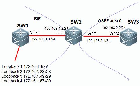
III. ConfigurationTips
1. Configure the basic IPaddresses.
2. On SW1 and SW2, enablethe RIP and propagate the corresponding interface to the RIP process.
3. On SW2 and SW3, enablethe OSPF and propagate the corresponding interface to the OSPF process.
4. On SW2, redistributethe route learned over RIP to the OSPF area.
5. Match the routes to belearned through the ACL or prefix list.
6. On SW2, redistributethe route learned over RIP to the OSPF area and filter the routes using thedistribute list tool.
III. ConfigurationSteps
1. Configure the basicIP addresses.
Ruijie(config)#hostname SW1
SW1(config)#interface GigabitEthernet 1/1
SW1(config-if-GigabitEthernet 1/1)#no switchport
SW1(config-if-GigabitEthernet 1/1)#ip address 192.168.1.1255.255.255.0
SW1(config-if-GigabitEthernet 1/1)#exit
SW1(config)#interface loopback 1
SW1(config-if-Loopback 1)#ip address 172.16.1.1255.255.255.224
SW1(config-if-Loopback 1)#exit
SW1(config)#interface loopback 2
SW1(config-if-Loopback 2)#ip address 172.16.1.33 255.255.255.240
SW1(config-if-Loopback 2)#exit
SW1(config)#interface loopback 3
SW1(config-if-Loopback 3)#ip address 172.16.1.49255.255.255.248
SW1(config-if-Loopback 3)#exit
SW1(config)#interface loopback 4
SW1(config-if-Loopback 4)#ip address 172.16.1.57 255.255.255.252
SW1(config-if-Loopback 4)#exit
Ruijie(config)#hostname SW2
SW2(config)#interface GigabitEthernet 1/2
SW2(config-if-GigabitEthernet 1/2)#no switchport
SW2(config-if-GigabitEthernet 1/2)#ip address 192.168.1.2255.255.255.0
SW2(config-if-GigabitEthernet 1/2)#exit
SW2(config)#interface GigabitEthernet 1/1
SW2(config-if-GigabitEthernet 1/1)#no switchport
SW2(config-if-GigabitEthernet 1/1)#ip address 192.168.2.1255.255.255.0
SW2(config-if-GigabitEthernet 1/1)#exit
Ruijie(config)#hostname SW3
SW3(config)#interface GigabitEthernet 1/2
SW3(config-if-GigabitEthernet 1/2)#no switchport
SW3(config-if-GigabitEthernet 1/2)#ip address 192.168.2.2255.255.255.0
SW3(config-if-GigabitEthernet 1/2)#exit
2. On SW1 and SW2,enable the RIP and propagate the corresponding interface to the RIP process.
SW1(config)#router rip
SW1(config-router)#version 2
SW1(config-router)#no auto-summary
SW1(config-router)#network 172.16.0.0
SW1(config-router)#network 192.168.1.0
SW1(config-router)#exit
SW2(config)#router rip
SW2(config-router)#version 2
SW2(config-router)#no auto-summary
SW2(config-router)#network 192.168.1.0
SW2(config-router)#exit
3. On SW2 and SW3,enable the OSPF and propagate the corresponding interface to the OSPF process.
SW2(config)#router ospf 1
SW2(config-router)#network 192.168.2.1 0.0.0.0 area 0
SW2(config-router)#exit
SW3(config)#router ospf 1
SW3(config-router)#network 192.168.2.2 0.0.0.0 area 0
SW3(config-router)#exit
4. On SW2,redistribute the route learned over RIP to the OSPF area.
SW2(config)#router ospf 1
SW2(config-router)#redistribute rip subnets
SW2(config-router)#exit
5. Match the routes tobe learned through the ACL or prefix list.
Note:
1) The tools for matching route entriesinclude the ACL and the prefix list. Chooseone of the tools.
SW2(config)#ip access-list standard 1
SW2(config-std-nacl)#10 permit 172.16.1.32 0.0.0.0
SW2(config-std-nacl)#20 permit 172.16.1.48 0.0.0.0
SW2(config-std-nacl)#30 permit 172.16.1.56 0.0.0.0
SW2(config-std-nacl)#exit
2) To match the route prefix with masks in different lengths in a largenetwork segment, the prefix list is recommended. You can also use the ACL,which requires a few more entries to be written.
For example, to matchroute entries 172.16.1.32/27, 172.16.1.48/28, and 172.16.1.56/29, the ACLapproach requires you to write three access control entries (ACEs) while theprefix list tool requires you to write only one entry.
1) Use the ACL to matchroute entries.
Note:
In this example, the ACLmatches the route entries. Therefore, you can use the mask 0.0.0.0 to exactlymatch the corresponding route entries.
2) Use the prefix list tomatch route entries.
Note:
a. The prefix listmatches route entries only and does not filter data packets.
b. The prefix listmatches the subnet of a network segment. ge indicates the minimal numberof bits and le indicates the maximal number of bits.
c. The prefix list ismatched from top to bottom with the last one being an implicit deny anyentry.
SW2(config)#ip prefix-list ruijie seq 10 permit 172.16.1.0/24ge 28 le 30 ------>Define a prefix list ruijie to match route entrieswhose prefix is 172.16.1.0/24 and subnet mask equals or is greater than 28 andequals or is smaller than 30.
6. On SW2, redistributethe route learned over RIP to the OSPF area and filter the routes using thedistribute list tool.
Note:
1. The distribute listfilters route entries matched by the ACL or prefix list. That is, the ACL andprefix list determine which route entries are filtered.
2. The distribute list can used in route protocol redistribution, route propagationbetween Routing Information Protocol (RIP) neighbors(route filtering is supported because routes are delivered between RIPneighbors), and route submission toroute tables in OSPF (ISAs rather than routes aredelivered between OSPF neighbors and ISAs between OSPF neighbor cannot befiltered).
The following describeshow the distribute list uses the ACL and the prefix list with examplesrespectively.
1. The distribute listinvokes the ACL for route filtering.
SW2(config)#router ospf 1
SW2(config-router)#distribute-list 1 out rip
SW2(config-router)#exit
2. The distribute listinvokes the prefix list for route filtering.
SW2(config)#router ospf 1
SW2(config-router)#distribute-list prefix ruijie out rip
SW2(config-router)#exit
Supplements:
1. To filter routeentries delivered between RIP neighbors by using the distribute list, run thefollowing command:
SW2(config)#router rip
SW2(config-router)#distribute-list 1 in GigabitEthernet 1/2----->1indicates the ACL 1. You can also use the prefix list. in indicates a routeentry learned from a neighbor. out indicates a route entry delivered to aneighbor. You can also add the specific interface.
2. To filter routeentries delivered to the route table in OSPF by using the distribute list, runthe following command:
SW2(config)#router ospf 1
SW2(config-router)#distribute-list 1 in---->1indicates the ACL 1. You can also use the prefix list. The direction must beset to in.
V. Verification
Check the route entrieson SW3. If the route entries learned by SW3 include 172.16.1.32/28,172.16.1.48/29, and 172.16.1.56/30, the distribute list is configuredcorrectly.
SW3#show ip route
Codes: C - Connected, L - Local, S - Static
R - RIP, O - OSPF, B - BGP, I - IS-IS, V -Overflow route
N1 - OSPF NSSA external type 1, N2 - OSPFNSSA external type 2
E1 - OSPF external type 1, E2 - OSPFexternal type 2
SU - IS-IS summary, L1 - IS-IS level-1, L2- IS-IS level-2
IA - Inter area, * - candidate default
Gateway of last resort is no set
O E2 172.16.1.32/28 [110/20] via 192.168.2.1, 00:02:45,GigabitEthernet 1/2
O E2 172.16.1.48/29 [110/20] via 192.168.2.1, 00:02:29,GigabitEthernet 1/2
O E2 172.16.1.56/30 [110/20] via 192.168.2.1, 00:02:21,GigabitEthernet 1/2
C 192.168.2.0/24 is directly connected, GigabitEthernet1/2
C 192.168.2.2/32 is local host.
2.9.3.5.3 Route Map
Scenario
To run a dynamic route protocol, such as theOSPF, on your network, you need to redistribute external routes, such as staticroutes, RIP routes, and BGP routes to the OSPF area on an ASBR. In this case,you may want to filter out desired route entries or redistribute routes withspecial requirements through route control and filter, or you may want tomodify some properties of the external route entries when being redistributedinto an OSPF area, for example, the metric value, next hop, and metric type (OE1, E2, O N1, or N2), and add special tags to some route entries so that adownstream router may perform route selection based on these tags accordingly.The route map is recommended for these application scenarios.
To run a dynamic routeprotocol, such as the BGP, on your network, route exchange and learning betweenBGP peers are necessary, or external routes, such as static routes, RIP routes,and OSPF routes may need be redistributed into the BGP area. In this case, youmay want to learn or delivery only desired route entries through route controland filter. In this case, the route map is recommended for routeredistribution.
You may want to modifysome properties, such as the metric, value, next hop, local preference, MEDvalue, and AS path of the route entries when they are learned or delivered toBGP peers or redistributed into the BGP area as external routes, or tag someroute entries so that a downstream router may perform route selection based onthese tags accordingly. The route map is recommended for these applicationscenarios.
Function Overview
You can control route update and modify route propertiesusing the route map tool.
I. NetworkingRequirements
On SW2, redistribute theRIP routes to the OSPF area and implement route filter on redistribution toallow only routes 172.16.1.32/28, 172.16.1.48/29, and 172.16.1.56/30 beredistributed to the OSPF area. The external routes to be redistributed intothe OSPF area are of route type OE1 and metric value 50.
II. Network Topology
III. ConfigurationTips
1. Configure the basic IPaddresses.
2. On SW1 and SW2, enablethe RIP and propagate the corresponding interface to the RIP process.
3. On SW2 and SW3, enablethe OSPF and propagate the corresponding interface to the OSPF process.
4. On SW2, redistributethe route learned over RIP to the OSPF area.
5. Match the routes to belearned through the ACL or prefix list.
6. Configure the routemap.
7. On SW2, redistributeRIP routes into the OSPF area and invoke the route map for route control.
III. ConfigurationSteps
1. Configure the basicIP addresses.
Ruijie(config)#hostname SW1
SW1(config)#interface GigabitEthernet 1/1
SW1(config-if-GigabitEthernet 1/1)#no switchport
SW1(config-if-GigabitEthernet 1/1)#ip address 192.168.1.1255.255.255.0
SW1(config-if-GigabitEthernet 1/1)#exit
SW1(config)#interface loopback 1
SW1(config-if-Loopback 1)#ip address 172.16.1.1255.255.255.224
SW1(config-if-Loopback 1)#exit
SW1(config)#interface loopback 2
SW1(config-if-Loopback 2)#ip address 172.16.1.33255.255.255.240
SW1(config-if-Loopback 2)#exit
SW1(config)#interface loopback 3
SW1(config-if-Loopback 3)#ip address 172.16.1.49255.255.255.248
SW1(config-if-Loopback 3)#exit
SW1(config)#interface loopback 4
SW1(config-if-Loopback 4)#ip address 172.16.1.57255.255.255.252
SW1(config-if-Loopback 4)#exit
Ruijie(config)#hostname SW2
SW2(config)#interface GigabitEthernet 1/2
SW2(config-if-GigabitEthernet 1/2)#no switchport
SW2(config-if-GigabitEthernet 1/2)#ip address 192.168.1.2255.255.255.0
SW2(config-if-GigabitEthernet 1/2)#exit
SW2(config)#interface GigabitEthernet 1/1
SW2(config-if-GigabitEthernet 1/1)#no switchport
SW2(config-if-GigabitEthernet 1/1)#ip address 192.168.2.1255.255.255.0
SW2(config-if-GigabitEthernet 1/1)#exit
Ruijie(config)#hostname SW3
SW3(config)#interface GigabitEthernet 1/2
SW3(config-if-GigabitEthernet 1/2)#no switchport
SW3(config-if-GigabitEthernet 1/2)#ip address 192.168.2.2255.255.255.0
SW3(config-if-GigabitEthernet 1/2)#exit
2. On SW1 and SW2,enable the RIP and propagate the corresponding interface to the RIP process.
SW1(config)#router rip
SW1(config-router)#version 2
SW1(config-router)#no auto-summary
SW1(config-router)#network 172.16.0.0
SW1(config-router)#network 192.168.1.0
SW1(config-router)#exit
SW2(config)#router rip
SW2(config-router)#version 2
SW2(config-router)#no auto-summary
SW2(config-router)#network 192.168.1.0
SW2(config-router)#exit
3. On SW2 and SW3,enable the OSPF and propagate the corresponding interface to the OSPF process.
SW2(config)#router ospf 1
SW2(config-router)#network 192.168.2.1 0.0.0.0 area 0
SW2(config-router)#exit
SW3(config)#router ospf 1
SW3(config-router)#network 192.168.2.2 0.0.0.0 area 0
SW3(config-router)#exit
4. On SW2,redistribute the route learned over RIP to the OSPF area.
SW2(config)#router ospf 1
SW2(config-router)#redistribute rip subnets
SW2(config-router)#exit
5. Match the routes tobe learned through the ACL or prefix list.
Note:
1) The tools for matching route entriesinclude the ACL and the prefix list. Chooseone of the tools.
SW2(config)#ip access-list standard 1
SW2(config-std-nacl)#10 permit 172.16.1.32 0.0.0.0
SW2(config-std-nacl)#20 permit 172.16.1.48 0.0.0.0
SW2(config-std-nacl)#30 permit 172.16.1.56 0.0.0.0
SW2(config-std-nacl)#exit
2) To match thesub-routes of one network segment, the prefix list offers more convenience thanthe ACL. You can also use the ACL, which requires a few more entries to bewritten.
For example, to matchroute entries 172.16.1.32/27, 172.16.1.48/28, and 172.16.1.56/29, the ACLapproach requires you to write three access control entries (ACEs) while theprefix list tool requires you to write only one entry.
1) Use the ACL to matchroute entries.
Note:
In this example, the ACLmatches the route entries. Therefore, you can use the mask 0.0.0.0 to exactlymatch the corresponding route entries.
2) Use the prefix list tomatch route entries.
Note:
a. The prefix listmatches route entries only and does not filter data packets.
b. The prefix listmatches the subnet of a network segment. ge indicates the minimal numberof bits and le indicates the maximal number of bits.
3. The prefix listmatches routes from top to bottom, which is the same as the ACL.
SW2(config)#ip prefix-list ruijie seq 10 permit 172.16.1.0/24ge 28 le 30 ---->Define a prefix list ruijie to match route entrieswhose prefix is 172.16.1.0/24 and subnet mask equals or is greater than 28 andequals or is smaller than 30.
6. Configure the routemap.
Note:
a. The route map can beused for route filter and route property modification.
b. The route map canmatch routes with more conditions than the distribute list. The route mapsupports the match of route entries, metric values, metric types, and so on,while the distribute list matches only route entries.
3. The route map is executed from top tobottom with the last one being animplicit deny any entry.
4. The route mapexecution logics are as follows:
route-map aaa permit 10
match x y z ----->Multiple matchconditions listed from left to right indicate "or", that is, thatonce one condition is matched, the whole statement is matched.
match a
set b ----->Multiple setstatements listed from top to bottom indicate that these set actions areexecuted simultaneously.
set c
route-map aaa permit 20
match p
match q ----->Multiple matchconditions listed from top to bottom indicate "and", that is, thatonly all conditions are met, the whole statement is matched.
set r
route-map aaa deny any (implicit in the system)
The execution logics areas follows:
If (x or y or z)
then set(b and c)
else if (p and q)
then set r
else deny
The match ip addressstatement in the route map can match the ACL or the prefix list. Choose eitherof the two methods. See the following examples:
1. Using the ACL in thematch ip address statement
SW2(config)#route-map aaa permit 10
SW2(config-route-map)#match ip address 1
SW2(config-route-map)#set metric-type type-1
SW2(config-route-map)#set metric 50
SW2(config-route-map)#exit
2. Using the prefix listin the match ip address statement
SW2(config)#route-map aaa permit 10
SW2(config-route-map)#match ip address prefix-list ruijie
SW2(config-route-map)#set metric-type type-1
SW2(config-route-map)#set metric 50
SW2(config-route-map)#exit
7. On SW2,redistribute RIP routes into the OSPF area and invoke the route map for routecontrol.
Note:
SW2(config)#router ospf 1
SW2(config-router)#redistribute rip subnets route-map aaa
SW2(config-router)#exit
Supplements:
The configuration commandfor invoking the route map on a BGP neighbor is as follows:
SW2(config)#router bgp 1
SW2(config-router)#neighbor 10.1.1.1 route-map aaa in----->inindicates controlling routes learned from the BGP neighbor and out indicatescontrolling routes propagated to the BGP neighbor. (To implement route controlon a BGP neighbor using the route map, soft delete the routes of the BGP tomake the configurations take effect after the route map is configured. Do notperform the operation at service peaks.)
V. Verification
Check the route entrieson SW3. If SW3 has learned route entries 172.16.1.32/28, 172.16.1.48/29,172.16.1.56/30 of OE1 and the internal costs are covered, the route map isconfigured correctly for route control.
SW3#show ip route
Codes: C - Connected, L - Local, S - Static
R - RIP, O - OSPF, B - BGP, I - IS-IS, V -Overflow route
N1 - OSPF NSSA external type 1, N2 - OSPF NSSAexternal type 2
E1 - OSPF external type 1, E2 - OSPF externaltype 2
SU - IS-IS summary, L1 - IS-IS level-1, L2 -IS-IS level-2
IA - Inter area, * - candidate default
Gateway of last resort is no set
O E1 172.16.1.32/28 [110/51] via 192.168.2.1, 00:03:14,GigabitEthernet 1/2
O E1 172.16.1.48/29 [110/51] via 192.168.2.1, 00:03:14,GigabitEthernet 1/2
O E1 172.16.1.56/30 [110/51] via 192.168.2.1, 00:03:14,GigabitEthernet 1/2
C 192.168.2.0/24 is directly connected, GigabitEthernet1/2
C 192.168.2.2/32 is local host.
2.9.3.6 Policy Routing
Scenario
If there are multiple interconnected linksbetween the convergence and core devices or between the core and egress routerson your network, a common route table may not satisfy the load or redundancyrequirement; or, new route access requirements emerge with deployment of newservices on the network, and you do not want to adjust the complicated OSPFroute control and selection policies previously planned, you can use the policyrouting technology to arrange new route selection for the new requirements. Youcan choose a designated link to forward data rather than using the traditionalroute table.
The policy routingtechnology is also recommended for another common application scenario: Thereare multiple routers or firewalls between the core devices and the networkegress devices. They corresponds to links of different ISPs, for example, ChinaTelecom (100M), China Unicom (50M), and CERNET (1G). You may want to distributeyour Intranet traffic to the three links based on the link load and bandwidthusage, for example, distribute the traffic of teaching buildings, researchinstitutions, and office buildings to the CERNET egress, the traffic of thelibrary, audio-visual education center, and administration building to theChina Unicom egress, and all other traffic (for example, traffic of studentdormitories) to the China Telecom egress. In addition, data traffic accessingCERNET resources is distributed to the CERNET egress. Traffic is distributedbased on the service type. The Telecom, Unicom, and CERNET links serve as abackup link of each other at link failure.
I. NetworkingRequirements
As shown in the followingtopology, there are two egress switches, Switch 3 and Switch 4, between Switch1 and the Internet. Distribute the Internet access traffic from the Intranet172.16.1.0/24 to Switch 3 and the Internet access traffic from the Intranet172.16.2.0/24 to Switch 4.
II. Network Topology
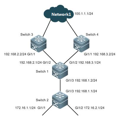
III. ConfigurationTips
1. Configure the basic IPaddresses.
2. Configure the basic IProutes to enable full reachability through the entire network.
3. On Switch 1, configurethe ACL to match the Intranet traffic.
4. Configure the policyrouting.
5. Apply policy routing.
IV. ConfigurationSteps
1. Configure the basicIP addresses.
Ruijie(config)#hostname SW1
SW1(config)#interface gigabitEthernet 1/3
SW1(config-if-GigabitEthernet 1/3)#no switchport
SW1(config-if-GigabitEthernet 1/3)#ip address 192.168.1.1255.255.255.0
SW1(config-if-GigabitEthernet 1/3)#exit
SW1(config)#interface gigabitEthernet 1/2
SW1(config-if-GigabitEthernet 1/2)#no switchport
SW1(config-if-GigabitEthernet 1/2)#ip address 192.168.2.1255.255.255.0
SW1(config-if-GigabitEthernet 1/2)#exit
SW1(config)#interface gigabitEthernet1/2
SW1(config-if-GigabitEthernet 1/2)#no switchport
SW1(config-if-GigabitEthernet 1/2)#ip address 192.168.3.1255.255.255.0
SW1(config-if-GigabitEthernet 1/2)#exit
Ruijie(config)#hostname SW2
SW2(config)#interface gigabitEthernet 1/3
SW1(config-if-GigabitEthernet 1/3)#no switchport
SW2(config-if-GigabitEthernet 1/3)#ip address 192.168.1.2255.255.255.0
SW2(config-if-GigabitEthernet 1/3)#exit
SW2(config)#interface gigabitEthernet 1/1
SW2(config-if-GigabitEthernet 1/1)#no switchport
SW2(config-if-GigabitEthernet 1/1)#ip address 172.16.1.1255.255.255.0
SW2(config-if-GigabitEthernet 1/1)#exit
SW2(config)#interface gigabitEthernet 1/2
SW2(config-if-GigabitEthernet 1/2)#no switchport
SW2(config-if-GigabitEthernet 1/2)#ip address 172.16.2.1255.255.255.0
SW2(config-if-GigabitEthernet 1/2)#exit
Ruijie(config)#hostname SW3
SW3(config)#interface gigabitEthernet 1/1
SW3(config-if-GigabitEthernet 1/1)#no switchport
SW3(config-if-GigabitEthernet 1/1)#ip address 192.168.2.2255.255.255.0
SW3(config-if-GigabitEthernet 1/1)#exit
Ruijie(config)#hostname SW4
SW4(config)#interface gigabitEthernet 1/1
SW4(config-if-GigabitEthernet 1/1)#no switchport
SW4(config-if-GigabitEthernet 1/1)#ip address 192.168.3.2255.255.255.0
SW4(config-if-GigabitEthernet 1/1)#exit
2. Configure the basicIP routes to enable full reachability through the entire network.
SW1(config)#ip route 172.16.0.0 255.255.0.0 192.168.1.2
SW2(config)#ip route 100.1.1.0 255.255.255.0 192.168.1.1
SW3(config)#ip route 172.16.0.0 255.255.0.0 192.168.2.1
SW4(config)#ip route 172.16.0.0 255.255.0.0 192.168.3.1
3. On Switch 1,configure the ACL to match the Intranet traffic.
SW1(config)#ip access-list standard 10
SW1(config-std-nacl)#10 permit 172.16.1.0 0.0.0.255
SW1(config-std-nacl)#exit
SW1(config)#ip access-list standard 20
SW1(config-std-nacl)#10 permit 172.16.2.0 0.0.0.255
SW1(config-std-nacl)#exit
4. Configure thepolicy routing.
SW1(config)#route-map ruijie permit 10
SW1(config-route-map)#match ip address 10
SW1(config-route-map)#set ip next-hop 192.168.2.2
SW1(config-route-map)#exit
SW1(config)#route-map ruijie permit 20
SW1(config-route-map)#match ip address 20
SW1(config-route-map)#set ip next-hop 192.168.3.2
SW1(config-route-map)#exit
Note:
1. The route map executespolicy matching from top to bottom. When the data traffic matches a policy, itis forwarded based on the matched policy and is not longer matched to thefollow-up policies.
2. The route map has a deny anystatement on the bottom, whichenables normal IP route forwarding for data trafficthat does not match any policies and avoids discarding such Intranet traffic.
3. The set ip next-hopstatement allows you to set the IP address of the next hop or the egressinterface of the data packet. The IP address of the next hop is recommended.
5. Apply policyrouting.
SW1(config)#interface gigabitEthernet 1/3
SW1(config-if-GigabitEthernet 1/3)#ip policy route-mapruijie
SW1(config-if-GigabitEthernet 1/3)#exit
Note:
Policy routing must be applied on the in direction interface ofthe data packets, not the interface in the out direction. This is because policy routing sets the next hopof the data packet in force when it passes through the router. As the routerhas completed IP route modification on the data packet on the interface in theout direction, the data packet is sent from the interface directly and policyrouting applied on the out direction does not take effect.
V. Verification
Perform route trackingwith data packets destined for the Internet 100.1.1.0/24 with source addresseson SW2. If the data packet sourced from 172.16.1.0/24 reaches the Internetthrough R3 and the data packet sourced from 172.16.2.0/24 reaches the Internetthrough Switch 4, policy routing is configured correctly.
SW2#traceroute 100.1.1.1 source 172.16.1.1
< press Ctrl+C to break >
Tracing the route to 100.1.1.1
1 192.168.1.1 0 msec 0 msec 0 msec
2 192.168.2.2 10 msec 0 msec 10 msec
SW2#traceroute 100.1.1.1 source 172.16.2.1
< press Ctrl+C to break >
Tracing the route to 100.1.1.1
1 192.168.1.1 0 msec 0 msec 0 msec
2 192.168.3.2 10 msec 0 msec 10 msec
2.9.3.7 GR
Scenario
The Graceful Restart (GR)mechanism is suitable for the following application scenario: The core switchN18010 is equipped with two main control engines, or two N18010s are deployedto form a virtual switching unit (VSU). The switch interconnects withneighboring devices (such as convergence device 5750E over the convergence APport) in double links. The dynamic routing protocol (such as OSPF or BGP) isenabled for routing interactions with neighboring devices. In such a scenario,the GR function is strongly recommended. If services are switched to the backupengine on the failure of the active engine, or services are switched to thebackup switch on the failure of the active switch in the VSU, the GR functionensures that the OSPF and BGP route entries are retained on the switch and itsneighbors and that only the neighboring relationship reconvergence isestablished. In this way, data are forwarded without stop. (One data packet maybe lost during the process, determined by the actual test environment.)
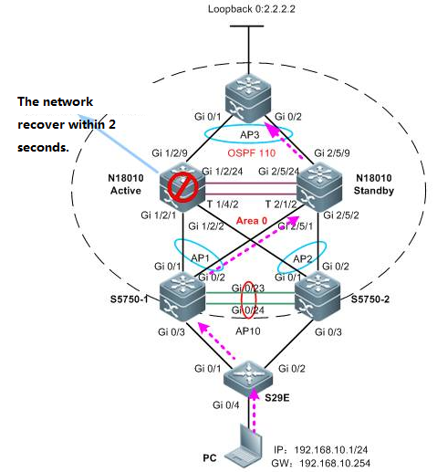
Function Overview
Developmentbackground
1. To support non-stopforwarding in a distributed architecture, the control plane must be separatedfrom the data plane.
2. Route computing andtable entry issuing are performed on the control plane while the data planeforwards data according to the forwarding entries issued by the control plane.
3. During active/standbyengine switchover, the data plane information on the backup engine enables itto quickly take over data forwarding tasks on the active engine. However, asthe backup engine does not have the control plane information (for example, thedynamic routing database and neighboring relationship information), itsneighboring devices will detect a dynamic routing protocol interrupt on theswitch and thereby start dynamic route reconvergence. In this way, a routingbackhole or routing bypass may result in on the entire network.
4. The dynamic routeconvergence period is in minute grade and does not satisfy the non-stopforwarding requirement.
The purpose of the GRtechnology is to carry out non-stop forwarding during routing protocol restart.The GR mechanism retains the route forwarding entries on the dynamic routingneighbors during active/standby switchover of the management board and updatesentries after the new neighboring negotiation convergence completes. Thisapproach keeps the network topology stable, retains the forwarding table, andensures service continuity.
Two roles of GR
Restarter: executes theGR function.
Helper: A neighboringdevice of the restarter. It helps the restarter to complete GR.
Configuration
Note: GR is enabled on theN18010 switch by default. If GR is disabled, enable the function as follows:
1. For RIP configuration, configure the GR Restarter on the local end.You do not have to configure the neighboring devices, as the RIP supports GRHelper.
Ruijie(config)#router rip
Ruijie(config-router)#graceful-restart
2. For OSPF configuration, configure the GR Restarter on the local end,and configure the GR Helper on neighboring devices. (The GR Helper function isenabled on Ruijie devices by default. The function is enabled on most devicesof other vendors. You are recommended to read the corresponding configurationmanual and make sure the function is enabled.)
Ruijie(config)#router ospf 1
Ruijie(config-router)#graceful-restart
3. For BGP configuration, configure the GR Restarter on both the localend and the neighboring devices.
Ruijie(config)#router bgp 1
Ruijie(config-router)#bgp graceful-restart
4. For LDP configuration, configure the GR Restarter on the local end,and configure the GR Helper on neighboring devices. (The GR Helper function isenabled on Ruijie devices by default. The function is enabled on most devicesof other vendors. You are recommended to read the corresponding configurationmanual and make sure the function is enabled.)
Ruijie(config)#mpls router ldp
Ruijie(config-mpls-router)#graceful-restart
2.9.4 IPv6
2.9.4.1 IPv6 Stateless Auto Configuration
Scenario
Stateless Auto Configuration is an important featureoffered by the IPv6 protocol. It allows the various devices attached to an IPv6network to connect to the Internet using the Stateless Auto Configurationwithout requiring any intermediate IP support in the form of a Dynamic HostConfiguration Protocol (DHCP) server.
With IPv6, a device on the link advertises any globalprefixes in Router Advertisement (RA) messages, as well as its willingness tofunction as a default device for the link. RA messages are sent periodicallyand in response to device solicitation messages, which are sent by hosts atsystem startup.
A node on the link can automatically configure globalIPv6 addresses by appending its interface identifier (64 bits) to the prefixes(64 bits) included in the RA messages.
I. Requirements
Use stateless auto configuration to assign IPv6prefix(64 bits) and use EUI-64 to assign IPv6 interface identifier(64 bits).
II. Network Topology
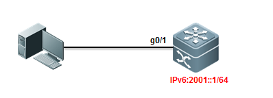
III. Configuration Tips
1. Enable IPv6 on Core switch and configurestateless autoconfiguration.
2. Enable RA (Router Advertisement) on Coreswitch.
IV. ConfigurationSteps
1. Enable IPv6 Routing:
Ruijie>enable
Ruijie#configureterminal
Ruijie(config)#ipv6unicast-routing ------>enableIPv6 Routing
Ruijie(config)#end
2. Assign IPv6 address to interface andenable RA
Ruijie#conft
Ruijie(config)#
Ruijie(config)#interfacegigabitEthernet 0/1
Ruijie(config-if-GigabitEthernet0/1)#no switchport
Ruijie(config-if-GigabitEthernet0/1)#ipv6 address 2001::1/64 ------>assign IPv6 address
Ruijie(config-if-GigabitEthernet0/1)#ipv6 enable ------>enable IPv6
Ruijie(config-if-GigabitEthernet0/1)#no ipv6 nd suppress-ra ------>enable RA
Ruijie(config-if-GigabitEthernet0/1)#end
Ruijie#wr
V. Verification
How to verify NIC status on a station
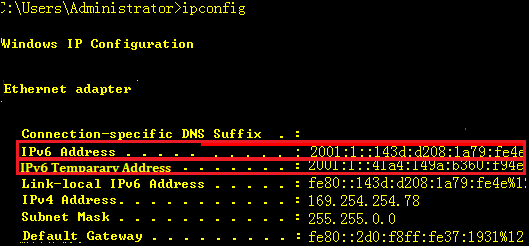
Note: System creates one more random IPv6 temporary addressafter enabling IPv6.
We suggest you to disable this feature inorder to control user unique ID and reduce network consumption etc.
Following sample shows how to disabletemporary address :
run->cmd->netsh->int ipv6->setprivacy state=disable
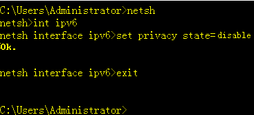
For more infomation about IPv6 temporaryaddress , see http://technet.microsoft.com/zh-cn/magazine/2007.08.cableguy.aspx
2.9.4.2 IPv6 Stateful Auto Configuration
2.9.4.2.1 DHCPv6 Server
Scenario
Stateful auto Configuration is the IPv6 equivalent ofDHCP. A new protocol, called DHCPv6 (and based closely on DHCP), is used topass out addressing and service information in the same way that DHCP is usedin IPv4. This is called "stateful" because the DHCP server and theclient must both maintain state information to keep addresses from conflicting,to handle leases, and to renew addresses over time.
Each DHCPv6 client and server is identified by a DHCPunique identifier (DUID). The DUID is carried in client identifier and serveridentifier options. The DUID is unique across all DHCP clients and servers, andit is stable for any specific client or server. DHCPv6 uses DUIDs based onlink-layer addresses for both the client and server identifier. The device usesthe MAC address from the lowest-numbered interface to form the DUID. Thenetwork interface is assumed to be permanently attached to the device.
When a DHCPv6 client requests two prefixes with thesame DUID but with different IAIDs on two different interfaces, these prefixesare considered to be for two different clients, and the interface informationis maintained for both.
I. Requirements
Switch acts as DHCPv6 client and acquiresfrom DHCPv6 Server for IPv6 prefix, DNS,and domain name.
Note: If station wants to acquire a IPv6address from a DHCPv6 Server, it must be running DHCPv6 client
So far Windows 7, VISTA and Windows Server2008 have built-in DHCPv6 client, but Windows XP and Windows Server2003 don't ,so you must install additional DHCPv6 client .
II. Network Topology
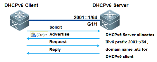
III. Configuration Tips
1. Configure switch as DHCPv6 Server andassign IPv6 address 2001::1/64 to port G1/1 connected to PC on switch
2. DHCPv6 Server assign IPv6 prefix2001::/64 to DHCPv6 client.
3. DNS Server IPv6 address is 2003::1/64
4.Domain name is "www.example.com.cn"
IV. ConfigurationSteps
Configuring DHCPv6 Server
1. Enable IPv6 routing:
server>enable
server#configureterminal
server(config)#ipv6unicast-routing
server(config)#end
2. Assign IPv6 addresses to interfaces
server#conft
server(config)#
server(config)#interfacegigabitEthernet 1/1
server(config-if-GigabitEthernet1/1)#no switchport
server(config-if-GigabitEthernet1/1)#ipv6 address 2001::1/64
server(config-if-GigabitEthernet1/1)#ipv6 enable
server(config-if-GigabitEthernet1/1)#end
3. Enable RA function and set M and O bits
①. DHCPv6 client acquires gateway infomation via RA ,not DHCPv6 Server
②. Set "managed address configuration" flag inRA packets which indicates that whether DHCPv6 client uses statefulautoconfiguration to acquires IPv6 address . By default , this flag doesn'tbeen set.
③. Set "other stateful configuration"flag inRA packets which indicates that whether DHCPv6 client use statefulautoconfiguration to acquires other infomation . By default , this flag doesn'tbeen set.
server>enable
server#configureterminal
server(config)#interfacegigabitEthernet 1/1
server(config-if-GigabitEthernet1/1)#no ipv6 nd suppress-ra ----->enable RAfunction
server(config-if-GigabitEthernet1/1)#ipv6 nd managed-config-flag ----->set M flag in RA
server(config-if-GigabitEthernet1/1)#ipv6 nd other-config-flag ----->set O flag in RA
server(config-if-GigabitEthernet1/1)#ipv6 nd prefix 2001::/64 no-autoconfig
server(config-if-GigabitEthernet1/1)#end
4. Configuring DHCPv6 Server
server(config)#ipv6dhcp pool ruijie ----->createDHCPv6 pool
server(dhcp-config)#domain-namewww.example.com.cn ----->configure domain name
server(dhcp-config)#dns-server2003::1 ----->configure DNSServer
server(dhcp-config)#prefix-delegationpool ruijie ----->associate DHCPv6prefix pool
server(dhcp-config)#exit
server(config)#ipv6local pool ruijie 2001::/64 64 ----->definelocal pool for clients
server(config)#end
5. Enable DHCPv6 Server on interface
client(config)#interfacegigabitEthernet 1/1
client(config-if-GigabitEthernet1/1)#ipv6 dhcp server ruijie ----->enable DHCPv6service on interface
client(config-if-GigabitEthernet1/1)#end
Configuring DHCPv6 Client
Enable DHCPv6 client under interface
client(config)#interfaceFastEthernet 0/11
client(config-FastEthernet0/11)#no switchport
client(config-FastEthernet0/11)#ipv6 enable
client(config-FastEthernet0/11)#ipv6 dhcp client pd rj ----->enable DHCPv6 client and prefixsolicitation on the interface
V. Verification
1. How to display status of DHCPv6 pool
server#showipv6 dhcp pool
DHCPv6pool: ruijie
Prefix pool: ruijie
preferred lifetime 3600, valid lifetime 3600
DNS server: 2003::1
Domain name: www.example.com.cn
2. How to display DHCPv6 Server assignment
server#showipv6 dhcp binding
Client DUID: 00:03:00:01:00:1a:a9:7d:88:97
IAPD: iaid 11, T1 1800, T2 2880
Prefix: 2001::/64
preferred lifetime 3600, valid lifetime 3600
expires at Jul 17 2011 18:30 (3570 seconds)
3. How to display DHCPv6 client status oninterface
client#showipv6 dhcp int f0/11
FastEthernet0/11 is in client mode
State is IDLE
next packet will be send in : 1525 seconds
List of known servers:
DUID: 00:03:00:01:00:1a:a9:15:c9:b5
Reachable via address: FE80::21A:A9FF:FE15:C9B6
Preference: 0
Configuration parameters:
IA PD: IA ID 0xb, T1 1800, T2 2880
Prefix: 2001::/64
preferred lifetime 3600, valid lifetime 3600
expires at Jul 17 2011 17:55 (3325 seconds)
Prefix name: ruijie
DNS server: 2003::1
Domain name: www.example.com.cn
Rapid-Commit: disable
2.9.4.2.2 DHCPv6 Relay
Scenario
The DHCPv6 relay forwards DHCPv6 messages between theDHCPv6 server and the DHCP client. When the DHCP server and the DHCP client arenot in the same physical network, the DHCP relay is responsible for forwardingthe DHCP solicit and reply messages. The forwarding process is different fromrouting forwarding, which features transparent transmission. Generally, therouter will not modify the contents of IP packets. Upon receiving the DHCPmessage, the DHCP relay will regenerate and forward another one. The DHCP relayis just like a DHCP server for the DHCP clients and a DHCP client for the DHCPserver.
I. Requirements
DHCPv6 Server Station(Windows 2008) assignsIPv6 prefix to DHCPv6 client(station) , and switch acts as DHCPv6 Relay
II. Network Topology
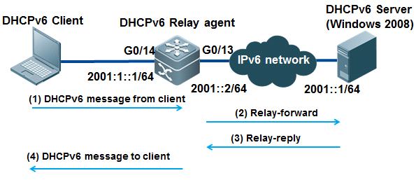
III. Configuration Tips
1. Configuring DHCPv6 Server
2. Enable IPv6 routing on DHCPv6 Relay agent
IV. ConfigurationSteps
Configuring DHCPv6 Relay agent
1. Enable IPv6 routing
Ruijie>enable
Ruijie#configureterminal
Ruijie(config)#ipv6unicast-routing
Ruijie(config)#end
2. Assign IPv6 address to interfaceconnected to DHCPv6 Server ,then enable IPv6 on that interface
Ruijie(config)#intg0/13
Ruijie(config-if-GigabitEthernet0/13)#no switchport
Ruijie(config-if-GigabitEthernet0/13)#ipv6 enable
Ruijie(config-if-GigabitEthernet0/13)#ipv6 address 2001:1::1
Ruijie(config-if-GigabitEthernet0/13)#end
3. Create VLAN for DHCPv6 client and assigninterfaces connected to DHCPv6 client to that VLAN
Ruijie(config)#vlan2
Ruijie(config-vlan)#exit
Ruijie(config)#intg0/14
Ruijie(config-if-GigabitEthernet0/14)#switchport mode access
Ruijie(config-if-GigabitEthernet0/14)#switchport access vlan 2
Ruijie(config-if-GigabitEthernet0/14)#end
Ruijie#
4. Configure IPv6 Gateway for DHCPv6 clientand then enable DHCPv6 Relay
Ruijie#conft
Ruijie(config)#interfacevlan 2
Ruijie(config-if-VLAN2)# ipv6 address 2001:1::1/64
Ruijie(config-if-VLAN2)# ipv6 enable
Ruijie(config-if-VLAN2)# ipv6 dhcp relay destination 2001::1 ----->configure DHCPv6 Relay
3. Enable RA function and set M and O bits
①. DHCPv6 client acquires gateway infomation via RA ,not DHCPv6 Server
②. Set "managed address configuration" flag inRA packets which indicates that whether DHCPv6 client uses statefulautoconfiguration to acquires IPv6 address . By default , this flag doesn'tbeen set.
③. Set "other stateful configuration"flag inRA packets which indicates that whether DHCPv6 client use statefulautoconfiguration to acquires other infomation . By default , this flag doesn'tbeen set.
Ruijie>enable
Ruijie#configureterminal
Ruijie(config-if-VLAN2)# no ipv6 nd suppress-ra ----->enable RAfunction
Ruijie(config-if-VLAN2)# ipv6 nd managed-config-flag ----->set M flag of RA
Ruijie(config-if-VLAN2)# ipv6 nd other-config-flag -----> set O flag ofRA
Ruijie(config-if-VLAN2)# end
6. Configuring DHCPv6 Server
Configure Windows 2008 as DHCPv6 Server ,for detail information , see Microsoft corresponding guide.
V. Verification
How to display NIC status on station
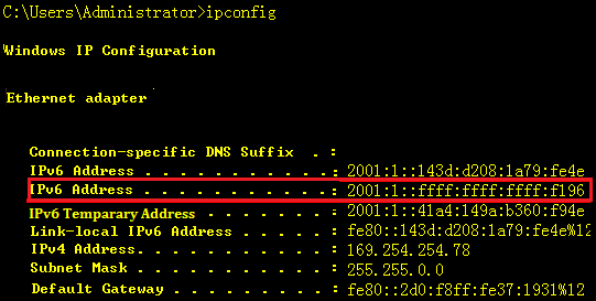
2. Use Ping to test connectivity
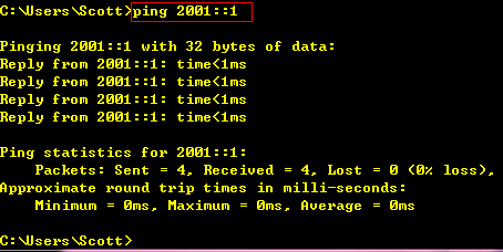
Note: System creates one more random IPv6 temporary addressafter enabling IPv6.
Suggest to disable this function in order tocontrol user unique ID and reduce network consumption etc.
Following sample shows how to disabletemporary address :
run->cmd->netsh->int ipv6->setprivacy state=disable
For more infomation about IPv6 temporaryaddress , see http://technet.microsoft.com/zh-cn/magazine/2007.08.cableguy.aspx
2.9.4.3 IPv6 Tunnel
2.9.4.3.1 ISATAP Tunnel
Scenario
Intrasite Automatic Tunnel Addressing Protocol (ISATAP)is an automatic overlay tunneling mechanism that uses the underlying IPv4network as a NBMA link layer for IPv6. ISATAP is designed for transporting IPv6packets within a site where a native IPv6 infrastructure is not yet available;for example, when sparse IPv6 hosts are deployed for testing. ISATAP tunnelsallow individual IPv4 or IPv6 dual-stack hosts within a site to communicatewith other such hosts on the same virtual link, basically creating an IPv6network using the IPv4 infrastructure.
ISATAP Address Format
ISATAP uses unicast addresses that include a 64-bitIPv6 prefix and a 64-bit interface identifier. The interface identifier iscreated in modified EUI-64 format in which the first 32 bits contain the value000:5EFE to indicate that the address is an IPv6 ISATAP address. The table below describes an ISATAP address format.

As shown in the table above, an ISATAP address consistsof an IPv6 prefix and the ISATAP interface identifier. This interfaceidentifier includes the IPv4 address of the underlying IPv4 link. The followingexample shows what an actual ISATAP address would look like if the prefix is2001::/64 and the embedded IPv4 address is 192.168.1.1. In the ISATAP address,the IPv4 address is expressed in hexadecimal as C0A8:0101 and the ISATAP is2001::0000:5EFE:C0A8:0101
I. Requirements
PCs in IPv4 network want to visit IPv6resource.
Build ISATAP tunnel between PC1 and S7606 toreach that goal.
II. Network Topology
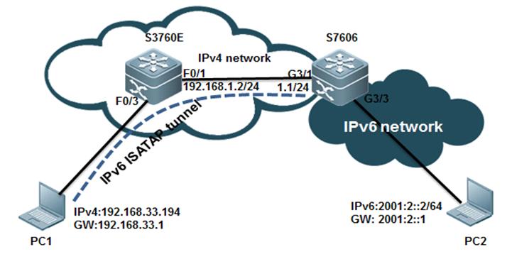
III. Configuration Tips
1. You must install IPv6 protocol on PCfirst (Win7 and Vista don't need) and then add an ISATAP tunnel route.
2. Configure tunnel interface tunnel mode,tunnel source IPv6 EUI address on ISATAP Device
IV. ConfigurationSteps
Configuring S7606
1. Create Tunnel Interface
S7606#conft
S7606(config)#interfaceTunnel 1
S7606(config-if-Tunnel1)#
2. Enable IPv6 on interface and assign IPv6address to that interface
S7606(config-if-Tunnel1)#ipv6 enable
S7606(config-if-Tunnel1)#ipv6 address 2001:1::/64 eui-64
3. Modify Tunnel mode
S7606(config-if-Tunnel1)#tunnel mode ipv6ip isatap
4. Specify Tunnel source using interface IDor IPv4 address(use IPv4 address here)
S7606(config-if-Tunnel1)#ip address 3.3.3.4 255.255.255.0
S7606(config-if-Tunnel1)#tunnel source 3.3.3.4
5. Enable RA . It is disable by default.
S7606(config-if-Tunnel1)#no ipv6 nd suppress-ra
6. Assign IPv6 address to Vlan 20 which isalso gateway for PC2
S7606(config)#vlan20
S7606(config-vlan)#intvlan 20
S7606(config-if-VLAN20)# ipv6 address 2001:2::2/64
S7606(config-if-VLAN20)# ipv6 enable
7. Configure interface conneted to S3760Eand configure a static route pointing to 192.168.33.0/24
S7606(config)#interfaceGigabitEthernet 3/1
S7606(config-if-GigabitEthernet3/1)# no switchport
S7606(config-if-GigabitEthernet3/1)# ip address 192.168.1.1 255.255.255.0
S7606(config-if-GigabitEthernet3/1)#exit
S7606(config)#iproute 192.168.33.0 255.255.255.0 192.168.1.2
S7606(config)#end
S7606#wr
Configuring S3760E
S3760E#conft
S3760E(config)#vlan10
S3760E(config-vlan)#interfaceVLAN 10
S3760E(config-if-VLAN10)# ip address 192.168.33.1 255.255.255.0
S3760E(config-if-VLAN10)#exit
S3760E(config)#interfaceFastEthernet 0/3
S3760E(config-if-FastEthernet0/3)# switchport access vlan 10
S3760E(config)#interfaceFastEthernet 0/1
S3760E(config-if-FastEthernet0/1)# no switchport
S3760E(config-if-FastEthernet0/1)# ip address 192.168.1.2 255.255.255.0
S3760E(config-if-FastEthernet0/1)#exit
S3760E(config)#iproute 0.0.0.0 0.0.0.0 192.168.1.1
Configuring PC
1.Configure a static route pointing to3.3.3.4 and enable ISATAP .
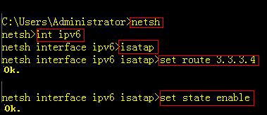
2.click Start -> Run -> services.msc,->enable "IP Helper" Service.
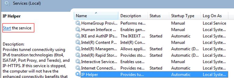
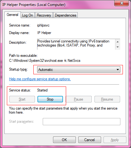
Note: You must double confirm that the steps above havebeen done, or PC will fail to create ISATAP Tunnel
V. Verification
1. How to display ISATAP status on PC
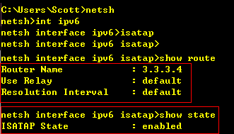

As figure shown above, PC1 has establishedISATAP Tunnel with S7606 successfully.
2. PC1 can use Ping to reach PC2 IPv6address through ISATAP Tunnel.
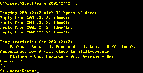
2.9.4.3.2 Manual Tunnel
Scenario
One manually configured tunnel is similar to onepermanent link set up between two IPv6 domains via the backbone network of theIPv4. It is applicable for the relatively fixed connections that have a higherdemand on security between two Area Border Routers or between an Area BorderRouter and a host.
On a tunnel interface, you must manually configure theIPv6 address, source IPv4 address (tunnel source) and destination IPv4 address(tunnel destination) of the tunnel. The nodes at the two end of the tunnel mustsupport the IPv6 and IPv4 protocol stacks. In practical application, tunnelsare always manuallyconfigured in pairs. You can think it as a point-to-pointtunnel.
I. Requirements
1. The figure shown below simulates ascenario that two IPv6 networks connects through an IPv4 network.
2. Configure Manual Tunnel on two IPv6boundary dual-stack switches to ensure that PC1 can communicate with PC2through IPv4 network.
II. Network Topology
III. Configuration Tips
1. You must install IPv6 protocol on PCfirst (Win7 and Vista don't need) and then add an ISATAP tunnel route.
2. Ensure all IPv4 routes have propagatedcorrectly first.
IV. ConfigurationSteps
1. Install IPv6 Protocol on Windows XP.
(Windows 7 and Windows Vista don't need)
2. Enable IPv6 on SVI 10 connected to customer,then configure basic IPv6 parameters.
S86E(config)#interface vlan 10
S86E(config-if-VLAN 10)#no shutdown
S86E(config-if-VLAN 10)#ipv6 enable
S86E(config-if-VLAN 10)# ipv6 address 2001:10::1/64
S86E(config-if-VLAN 10)# no ipv6 suppress-ra
Note: You cannot enable IPv6 between S3760-1and S3760-2 because the link only forward IPv4 traffic in order to simulate twoIPv6 networks is isolated by a IPv4 network.
3. Configure IPv6 Manual Tunnel
S86E(config)#interface Tunnel 1
S86E(config-if-Tunnel1)#ipv6 enable
S86E(config-if-Tunnel1)#tunnel source 10.1.1.1
S86E(config-if-Tunnel1)#tunnel destination 10.1.1.2
S86E(config-if-Tunnel1)#tunnel mode ipv6ip
4. Configure IPv6 Route
S86E(config)# ipv6 route 2001:20::/64 Tunnel 1
5. Show run on S3760-1
interfaceGigabitEthernet 0/1
noswitchport
noip proxy-arp
ipaddress 10.1.1.1 255.255.255.252
!
interfaceGigabitEthernet 0/12
switchportaccess vlan 10
!
interfaceVLAN 10
noip proxy-arp
ipaddress 192.168.10.254 255.255.255.0
ipv6address 2001:10::1/64
ipv6enable
noipv6 nd suppress-ra
!
interfaceTunnel 1
ipv6enable
tunnelsource 10.1.1.1
tunneldestination 10.1.1.2
!
ipv6route 2001:20::/64 Tunnel 1
!
6. Configuration on S3760-2 is the same toS3760 except for the IPv6 address.
V. Verification
1. Use PING to test connectivity between PC1and PC2
S3760-1#ping2001:20::1 source 2001:10::1
Typeescape sequence to abort.
Sending5, 100-byte ICMP Echos to 2001:20::1, timeout is 2 seconds:
Packetsent with a source address of 2001:10::1
!!!!!
Successrate is 100 percent (5/5), round-trip min/avg/max = 48/106/176 ms
2.9.5 Security
2.9.5.1 CPP
Overview
CPU Protect Policy (CPP) can effectively prevent malicious attacks inthe network by packet identification and attack packet suppression, which can:
1. Reduce the influence of attack packets onthe switch (CPU protection)
2. Enable load balance for the packets ofdifferent priority queues.
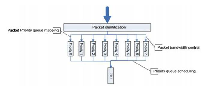
CPP adopts packet identification, packetbandwidth control, priority queue mapping and queue scheduling to protect CPUand key packets.
1. Packet Identification
Packet identification classifies all thepackets sent to the switch for processing, for example, ARP, BPDU and GVRP etc.
2. Packet Bandwidth Control
Administrator can configure bandwidth foreach type of packets to suppress attack packets at high rate in the network.
3. Priority Queue Mapping
Eight priority queues are supported. You canconfigure priority queue for each type of packets.
4. Queue Scheduling
Poll scheduling algorithm is used to ensurethat the protocol packets of different priority queues are sent to CPU forprocessing in time. Each queue is of the same scheduling weight.
Configuration
I. Requirements
As the figure shown below , administrator connects aS5750E switch to a S8606 switch through layer 3 port and is pinging S5750E with18024 bytes ICMP packet on S8606 ,then he finds that there's a regular RTO(about 3 RTO every 1000 packets) . Administrator has disabled NFPP ICMP-Guardon both switches but this issue still occurs. Later administrator finds that itis because of the default CPP setting that maks the RTO.
II. Network Topology
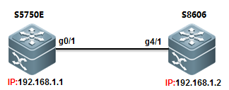
III. Configuration Tips
CPP commands on different series of switch varies, butyou can enter "cpu-protect" global command and use "?" todisplay the details command.
This example shows how to set CPP ARP value to 200000PPS on S86E:
Ruijie(config)#cpu-protect?
cpu Set cpu bandwidth
sub-interface Set globle control to packet
traffic-class Set traffic-class' configure
type Set packet's configure
Ruijie(config)#cpu-protecttype arp-request bandwidth 20000
Ruijie(config)#cpu-protecttype arp-reply bandwidth 20000
How to display CPP configuration
Ruijie#showcpu-protect
%cpuport bandwidth: 10000(pps)
Traffic-class Bandwidth(pps) Rate(pps)
------------- -------------- ---------
0 1000 0
1 1000 0
2 1500 0
3 8000 0
4 1500 0
5 1500 0
6 3500 0
PacketType Traffic-class Bandwidth(pps) Rate(pps) Drop(pps)
---------------- ------------- -------------- --------- ---------
bpdu 6 1000 0 0
arp-request 2 20000 0 0
This example shows how to set CPP ARP value to 200000PPS on S8600 :
Ruijie(config)# cpu-protect ?
sub-interface Config sub-interface pps or percent
type Add an extend type
Ruijie(config)#cpu-protecttype arp pps 20000
How to display CPP configuration
Ruijie#showcpu-protect summary
Type Pps Pri
---------------------------- ---------
tp-guard 128 7
arp 20000 3
IV. ConfigurationSteps
1) Configuring S86E
Ruijie(config)#cpu-protecttype icmp bandwidth 5000 ------>set bandwidthof ICMP to 5000 PPS
Ruijie(config)#cpu-protecttraffic-class id 3 bandwidth 8000 ------>set bandwidthof traffic-class id 3 to 8000 PPS because ICMP belongs to traffic-class id 3
Ruijie(config)#cpu-protectcpu bandwidth 10000 ------>set global cpubandwidth to 10000
2) Configuring S8606
Ruijie(config)#cpu-protecttype ipv4-icmp-local pps 10000 ------>set bandwidth of ICMP to 10000PPS
V. Verification
1) How to display CPP configuration for ICMPon S86E
CPP bandwidth of ICMP is 5000 packets persecond(pps) and ICMP belongs to Traffic-class id is 3
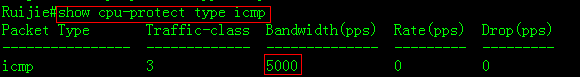
Bandwidth of traffic-class 3 is 8000 pps
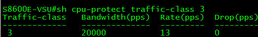
Maximum number of packets sended CPU toprocess is 10000 pps
![]()
2) How to display CPP configuration on S8600
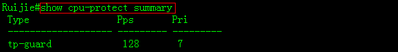
Show CPP statistic of each type of packetsin mainboard.
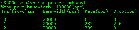
Show CPP statistic of each type of packetsin each slot.
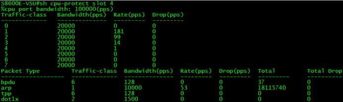
Show CPP statistic of a specific type ofpacket

2.9.5.2 NFPP
Overview
(NFPP) protects switch itself from being attack andcouln't replace security feature that defend ARP spoofing. NFPP is enabled bydefault.
Recommend operation:
1. Actually,no need to tune NFPP parameter on accessswitch because on not-gateway equipment ,there're no gateway IP address , norouting protocol , no administrator protocol , no extra cpu consumption ,andless beening attacked.
2. On aggregation switch , default NFPP port-basethreshold -----rate-limit 100PPS / attact-detection 200PPS is small whenthere're many users and many ARP attacks , the small threshold may lead tonormal ARP packets loss .Best practice is tune the threshold to rate-limit500PPS / attact-detection 800PPS for each port and no need to adjust otherip/mac base parameters.
3. Not suggest to turn on isolation function except forthe very often attacks that makes cpu utilization up to 80% ~90% and need toincrease attack-threshold in case of misjudgement.
NFPP is the abbreviation of Network FoundationProtection Policy.In the network, some malicious attacks put too much burden onthe switch, thus the CPU ofthe switch cannot operate normally.
DoS attack may lead to the consumption of a largeamount of the switch memory, entries and other resources, resulting in thesystem service failure.A large amount of the packet traffic uses the CPUbandwidth,resulting in the handling failure of the protocol packet and managepacket by the CPU, influencing the data forwarding, the device management ofthe administrator and the normal device/network running.A large amount of thepacket traffic consumes massive CPU resources, making the CPU being in thehigh-load status and influencing the device management of the administrator andthe normal device running.In the NFPP-enabled enviroment, it prevents the system from being attacked, releasingthe CPU load and ensuring the normal and stable operation of various systemservices and the whole network.
Most important sub-function of NFPP Overview:(Suggest adminitrator to adjust ARP-Guard and IP-Guardfunction in daily maintenance and keep the default value for other NFPPsub-function , like ND Guard ,DHCP Guard..)
ARP-Guard Overview:
The IP address is translated into the MAC address byARP protocol in the local area network(LAN). ARP protocol plays an importantrole in the network security. ARP DoS attack sends a large amount of illegalARP packets to the gateway, preventing the gateway from providing the services.To deal withthis attack, on one hand, you can configure the rate-limit of theARP packet, on the other hand, you can detect and isolate the attack source.
The ARP attack detection could be host-based orport-based. Host-based ARP attack detection could be classified into thefollowing two types again: source IP address/VID/port-based and source MACaddress/VID/port-based. For eachattack detection, you can configure therate-limit threshold and warning threshold. The ARP packet will be dropped whenthe packet rate exceeds the rate-limit threshold. When the ARP packet rateexceeds the warning threshold, it will prompt the warning messages and send theTRAP message. The host-based attack detection can isolate the attack source.
IP-Guard Overview:
As is known to all, many hacker attacks and the networkvirus invasions begin with the network scanning. To this end, a large amount ofthe scanning packets take up the network bandwidth, leading to the abnormalnetwork communication.
Ruijie Layer-3 device provides the IP-guard function toprevent the attacks from the hacker and the virus such as “Blaster”, reducingthe CPU burden of the layer-3 devices.
There are two types of the IP packet attack:
1) Scanning the destination IP address change:not onlyconsumes the network bandwidth and increases the device burden, but also is aprelude of the hacker attack.
2) Sending the IP packets to the inexistentdestination IP address at the high-rate: for the layer-3 device, the packetsare directly forwarded by the switching chip withoutthe consumption of the CPUresources if the destination IP address exists. While if the destination IPaddress is inexistent, the ARP request packetsare sent from the CPU to ask forthe corresponding MAC address for the destination IP address when the IPpackets are sent to the CPU. It consumes the CPU resources if many IP packetsare sent to the CPU.
The workaround for this attack: on one hand, you mayconfigure the IP packet rate-limit; on the other hand, you may detect andisolate the attack source.
The IP attack detection could be host-based orport-based. Host-based ARP attack detection adopts the combination of source IPaddress/VID/port-based. For each attack detection, you can configure therate-limit threshold and warning threshold. The IP packet will be dropped whenthe packet rate exceeds the rate-limit threshold. When the ARP packet rateexceeds the warning threshold, it will prompt the warning messages and send theTRAP message. The host-based attack detection can isolate the attack source.
Configuring NFPP
Configuration
I. Requirements
Core switch carries 3000 users,and figure below onlyshows one of all the ports and this port carries about 200 users. As to Accessswitch , each port can carry maximun 6 users. Administrator can enable DHCPSnooping and DAI to ensure the stability of network and prevent ARP spoofing.Inaddition ,administrator can enable NFPP to protect switch itself from beeningattack.
II. Network Topology
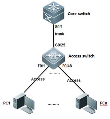
III. Configuration Tips
1.Disable NFPP on uplink port on access switch andadjust CPP parameters(In a scenario that have DAI enabled , the default CPP ARPrate-limit 180PPS is not enough and can probably drops the exceeding but legalARP packets )
2.Adjust NFPP parameters(PerPort , Per IP and Per MAC)
3.Adjust the printing rate of NFPP logs.
IV. ConfigurationSteps
Configuration Access Switch:
1. Configure DAI .For more information, see Chapter ARP Spoofing Protection
Ruijie#configureterminal
Ruijie(config)#vlan10
Ruijie(config-vlan)#exit
Ruijie(config)#iparp inspection vlan 10
Ruijie(config)#ipdhcp snooping
Ruijie(config)#interfacegigabitEthernet 0/25
Ruijie(config-if-GigabitEthernet0/25)#switchport mode trunk
Ruijie(config-if-GigabitEthernet0/25)#ip dhcp snooping trust
Ruijie(config-if-GigabitEthernet0/25)#ip arp inspection trust
Ruijie(config-if-GigabitEthernet0/25)#exit
Ruijie(config)#interfacerange fastEthernet 0/1-24
Ruijie(config-if-range)#switchportaccess vlan 10
Ruijie(config-if-range)#end
Ruijie#
2. Configure NFPP :
1) Configuringglobal NFPP
NFPP is enabled bydefault , and you don't need to adjust default NFPP parameters and you candisable NFPP on uplink interface ,then adjust CPP ARP parameter if DAI isenabled in case that CPP and NFPP drop the exceeding but legal ARP packetsreceived from Core switch .
Ruijie(config)#cpu-protecttype arp pps 500 ------>no need to adjust CPP if DAI isdisabled
Tune NFPP parameters as below :
Ruijie(config-nfpp)#log-bufferentries 1024 ------>set the NFPP log-buffercapability to 1024 (256 by default)
Ruijie(config-nfpp)#log-bufferlogs 1 interval 300 ------>set the rate of printing syslog .NFPP prints syslog every 300 seconds .
Ruijie(config-nfpp)#exit
Ruijie(config)#
2) Configuring NFPP in interface configuration mode
Disable NFPP on uplink interfaces
Ruijie(config)#intg0/25
Ruijie(config-if-GigabitEthernet0/25)#no nfpp arp-guard enable ------>disableARP-Guard
Ruijie(config-if-GigabitEthernet0/25)#no nfpp dhcp-guard enable ------>disableDHCP-Guard
Ruijie(config-if-GigabitEthernet0/25)#no nfpp dhcpv6-guard enable ------>disableDHCPv6-Guard
Ruijie(config-if-GigabitEthernet0/25)#no nfpp icmp-guard enable ------>disableICMP-Guard
Ruijie(config-if-GigabitEthernet0/25)#no nfpp ip-guard enable ------>disableIP-Guard
Ruijie(config-if-GigabitEthernet0/25)#no nfpp nd-guard enable ------>disableND-Guard
Ruijie(config-if-GigabitEthernet0/25)#exit
Ruijie(config)#
Configuration on Core Switch :
Ruijie(config)#nfpp
Ruijie(config-nfpp)#arp-guard attack-threshold per-port 800 ------>set theARP-Guard attack threshold to 800pps per-port. When the ARP packet sent fromthe port exceeds the attack threshold , the attack is detected and systemprompts.
Ruijie(config-nfpp)#arp-guard rate-limit per-port 500 ------>set theARP-Guard rate limit to 500pps (100 by default) per-port and ARP-Guard dropsthe exceeding ARP packets when rate exceeds.
Ruijie(config-nfpp)#log-bufferentries 1024 ------>set the NFPP log-buffer capability to 1024 (256 bydefault)
Ruijie(config-nfpp)#log-bufferlogs 1 interval 300 ------>set the rate of printing syslog . NFPP prints 1 syslogevery 300 seconds
Ruijie(config-nfpp)#exit
Ruijie(config)#
If you want to enable NFPP isolation, you shouldincrease rate-limit and attack-threshold in case that NFPP isolates the legalhosts.
Note:
1. Don't enable NFPP isolation on accessswitch.
2. Usually, we don't suggest you to enableNFPP isolation , but you can enable NFPP isolation if there're too manymalevolent attacks on Distribution Switch (Gateway) andCPU load is very heavy (above 90%) all the time.
Ruijie(config)#nfpp ------>enterNFPP configuration mode
Ruijie(config-nfpp)#arp-guard isolate-period 600 ------>When ARP packet from a host exceeds the attackthreshold , ARP-guard isolates the host for 600 seconds (The default value is0s, representing no isolation.)
Ruijie(config-nfpp)#arp-guard attack-threshold per-src-mac 30 ------>set the ARP-Guardattack threshold to 30pps (8 by default ) based on the MAC address.
Ruijie(config-nfpp)#arp-guard attack-threshold per-src-ip 30 ------>set theARP-Guard attack threshold to 30pps (8 by default ) based on the IP address.
Ruijie(config-nfpp)#arp-guard rate-limit per-src-mac 20 ------>set theARP-Guard rate limit to 20pps (4 by default) based on the MAC address andARP-Guard drops the exceeding ARP packets.
Ruijie(config-nfpp)#arp-guard rate-limit per-src-ip 20 ------>set theARP-Guard rate limit to 20pps (4 by default) based on the IP address andARP-Guard drops the exceeding ARP packets.
Ruijie(config-nfpp)#ip-guardattack-threshold per-src-ip 80 ------>set theIP-Guard attack threshold to 80pps based on the IP address.
Ruijie(config-nfpp)#ip-guardisolate-period 600 ------>When IP packetfrom a host exceeds the attack threshold , IP-guard isolates the host for 600seconds (The default value is 0s, representing no isolation.)
V. Verification
1. How to display NFPP ARP-Guardconfiguration
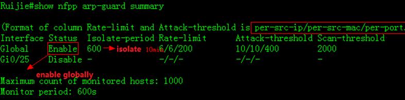
2. How to display ARP-Guard scan table
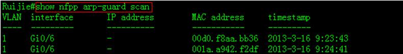
3. How to display isolated user
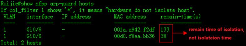
4. How to display NFPP Logs in buffer
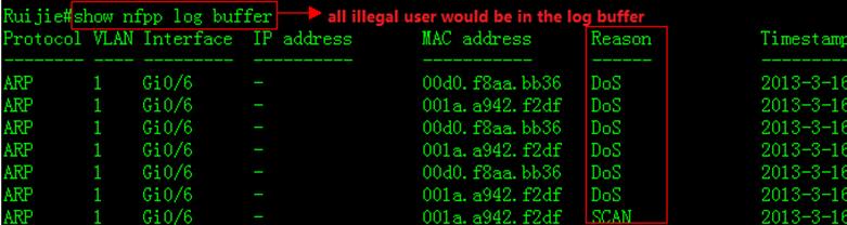
6. Common NFPP Syslog information
1) *Dec 26 13:46:10:%NFPP_ARP_GUARD-4-SCAN_TABLE_FULL:ARP scan table is full.
a. ARP scan table contains only the latest256 logs. When the ARP scan table is full, the latest record overwrite theoldest one. This log doens't have any impact on switch performance.
b. Use "clear nfpp log" EXECcommand to clear NFPP log buffer
c. Following example shows how to increaselog buffer size and decrease printing rate :
Ruijie(config)#nfpp
Ruijie(config-nfpp)#log-bufferentries 1024 ------>set NFPP logbuffer capability to 1024
Ruijie(config-nfpp)#log-bufferlogs 1 interval 300 ------>NFPP print 1 logevery 300 seconds
2.9.5.3 DHCP SNOOPING
Overview
DHCP Snooping:In the DHCP-enabled network, the general problem facingadministrator is that some users use private IP addresses rather thandynamically obtaining IP addresses. As a result, some users using dynamic IPaddresses cannot access the network, making network application more complex.In dynamic DHCP binding mode, the device records how legal users obtain IPaddresses during the course of DHCP Snooping for security purpose. There arethree waysof security control. The first one is to enable address binding forlegal users in conjunction with the IP Source Guard function; the second one isto use DAI to check the validity of users by controlling ARP; the third one isto bind the ARP message of legal users in conjunction with the ARP Checkfunction.It should be noted that given the limit of hardware entries in the firstmode, the switch supports limited DHCP users. Where there are too many users onthe switch, some legal users may not access the network for they cannot addhardware entries. In addition, the second method will influece the performanceof the switch at a large extent, because all ARP messages are forwarded andprocessed by CPU.
Some terms and functions used in DHCP Snooping areexplained below:
1) DHCP Request:Packets sentfrom DHCP Client to DHCP Server.
2) DHCP Ack:Packets sentfrom DHCP Server to DHCP Client.
3) DHCP Snooping TRUST Port:Because the packets for obtaining IP addresses throughDHCP are in the form of broadcast, some illegal servers may prevent users fromobtaining IP addresses, or even cheat and steal user information. To solve thisproblem, DHCP Snooping classifies the ports into two types: TRUST port andUNTRUST port. The device forwards only the DHCP reply packets received throughthe TRUST port while discarding all the DHCP reply packets from the UNTRUSTport. In this way, the illegal DHCP Server can be shielded by setting the portconnected to the legal DHCP Server as a TRUST port and other ports as UNTRUSTports.
4) DHCP Snooping Binding Database:By snooping the packets between the DHCP Clients andthe DHCP Server, DHCP Snooping combines the IP address,MAC address, VID, portand lease time into a entry to form a DHCP Snooping user database.
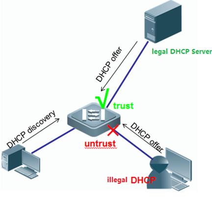
Configuration
I. Requirements
As figure shown below, Core switch acts asDHCP Server and assign IP address to stations.Administrator wants to enableDHCP Snooping in case that some users connect their household router to networkand the household router assigns IP address to stations ,then stations cannotaccess to the network once they require the wrong IP address.
II. Network Topology
III. Configuration Tips
1. Enable DHCP Snooping on Access switch andconfigure the uplink port as DHCP Snooping trust port
2. Configure Core switch as DHCP Server.
IV. ConfigurationSteps
Configuring Core Switch:
1. Enable DHCP Service on Core switch
Ruijie(config)#servicedhcp
2. Assign IP address to Vlan 1 which is theuser gateway
Ruijie(config)#interfacevlan 1
Ruijie(config-if-VLAN1)#ip address 192.168.1.254 255.255.255.0
Ruijie(config-if-VLAN1)#exit
3. Create DHCP pool
Ruijie(config)#ipdhcp pool vlan1
Ruijie(dhcp-config)#network192.168.1.0 255.255.255.0
Ruijie(dhcp-config)#dns-server218.85.157.99
Ruijie(dhcp-config)#default-router192.168.1.254
Ruijie(dhcp-config)#end
Ruijie#wr
Configuring Access Switch:
1. Enable DHCP Snooping on the accessswitch.
Ruijie>enable
Ruijie#configureterminal
Ruijie(config)#ipdhcp snooping
2. Configure the port connected to DHCPServer as DHCP Snooping trust port
Ruijie(config)#interfacegigabitEthernet 0/49
Ruijie(config-GigabitEthernet0/49)#ip dhcp snooping trust --------By default , all ports are DHCPSnooping untrust port. Only trust port can forward DHCP Offer and Ack packets
3 .Save configuration
Ruijie(config-GigabitEthernet0/49)#end
Ruijie#write ------> Confirm and save configuration
V. Verification
1. How to display DHCP assignment on DHCPServer.
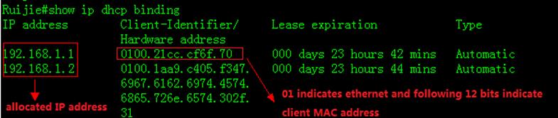
2. How to display NIC status on station .Start -> Run -> cmd -> ipconfig/all 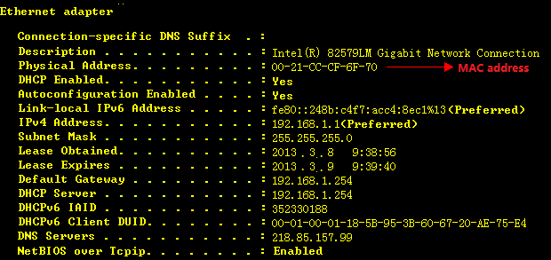
3. How to display DHCP Snooping bindingtable
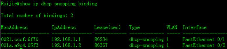
4. How to display DHCP Snooping status
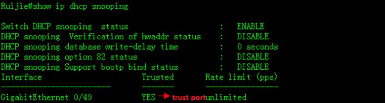
2.9.5.4 IP Source Guard
Overview
IP Source Guard:IPSource Guard maintains a hardware-based IP packet filtering database to filterpackets, guaranteeing that only the users matching the database can accessnetwork resources.The hardware-based IP packet filtering database isthe key forIP Source Guard to enable efficient security control in DHCP applications. Thisdatabase is on the basis of DHCP Snooping database. After IP Source Guard isenabled, the DHCP Snooping database is synchronized with the hardware-based IPpacket filtering database. In thisway, IP Source Guard can strictly filter IPpackets from clients on the device with DHCP Snooping enabled.
By default, once IP Source Guard is enabled on a port,all the IP packets traveling through the port (except for DHCP packets) will bechecked on the port. Only the users attaining IP addresses through DHCP and theconfigured static binding users can access the network. IP Source Guardsupports source MAC- and source IP-based filtering or source IP-basedfiltering. In the former case, IP Source Guard will check the source MAC andsource IP addresses of all packets and only allow those packets matching thehardware-based IP packet filtering database to pass through. In the lattercase, IP Source Guard checks the source IP addresses of IP packets.
I. Requirements
As figure shown below, Core switch acts asDHCP Server . Administrator wants to enable IP Source Guard to enhanced networksecurity and prevent those users who configure illegal static IP addressthemselfs from accessing the network.
II. Network Topology
III. Configuration Tips
1. Core switch acts as DHCP Server
2. Enable DHCP Snooping and IP Source Guard on Accessswitch to enhance network security
IV. Configuration Example
Configuring Core switch:
1. Enable DHCP Service
Ruijie(config)#servicedhcp
2. Assign IP address to Vlan 1 which is usergateway.
Ruijie(config)#interfacevlan 1
Ruijie(config-if-VLAN1)#ip address 192.168.1.254 255.255.255.0
Ruijie(config-if-VLAN1)#exit
3. Create DHCP pool .
Ruijie(config)#ipdhcp pool vlan1
Ruijie(dhcp-config)#network192.168.1.0 255.255.255.0
Ruijie(dhcp-config)#dns-server218.85.157.99
Ruijie(dhcp-config)#default-router192.168.1.254
Ruijie(dhcp-config)#end
Ruijie#wr
Configuring Access switch:
1. Enable DHCP Snooping
Ruijie>enable
Ruijie#configureterminal
Ruijie(config)#ipdhcp snooping ------>enable DHCP Snooping
2. Configure the port connected to DHCPServer as DHCP Snooping trust port
Ruijie(config)#interfacegigabitEthernet 0/49
Ruijie(config-GigabitEthernet0/49)#ip dhcp snooping trust ------>By default , all ports are untrustport. Only trust port can forward DHCP Offer and Ack packets
3. Enable IP Source Guard on port connected to Users
Ruijie(config)#interfacerange fastEthernet 0/1-2 ------>configure arange of interfaces
Ruijie(config-if-range)#ipverify source port-security ------>enable IP SourceGuard in mode "souce IP + MAC"
4. Configure static IP&MAC binding.Stations that matches the binding entry can pass IP Source Guard validationalso.
Ruijie(config)#ipsource binding 001a.a2bc.3a4d vlan 10 192.168.10.5 interface fa0/15
Ruijie(config)#interfacefastEthernet 0/15
Ruijie(config-fastethernet0/15)#ip verify source port-security ------>enable IPSource Guard in mode "souce IP + MAC"
5 . Save Configuration
Ruijie(config-if-range)#end
Ruijie#write
V. Verification
1. How to display DHCP assigement

2. How to display NIC status on station .Start -> Run -> cmd -> ipconfig/all
3. How to display DHCP snooping bindingtable
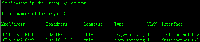
4. How to display IP Source Guard table
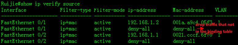
5. Use ping to test connectivity whenstation passes IP source Guard validation.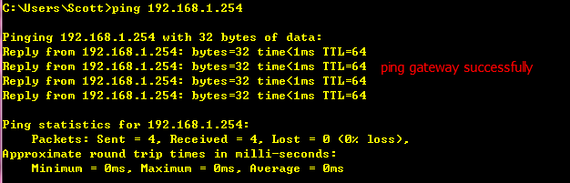
6. How to display ARP table on station.
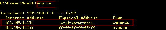
7. Execute "ipconfig/release" torelease IP address assigned from DHCP, then configure static IP address
![]()
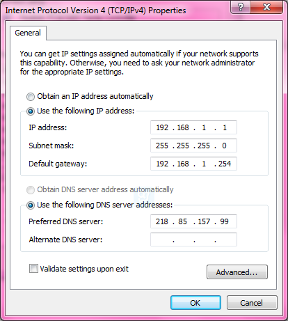
8. Confirm that we have assigned static IPaddress to station
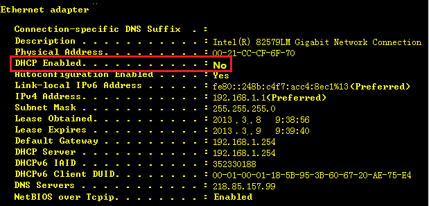
9. There's no binding entry when we displayIP source Guard table
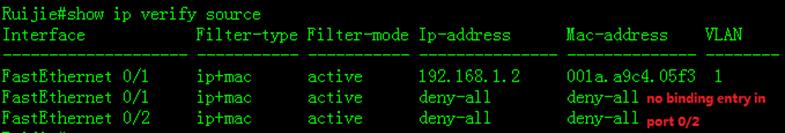
10. Use ping to test the connectivity whenstation doesn't pass the IP source Guard validation
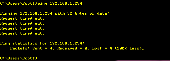
11. ARP entry still exists because IP SourceGuard only detects IP packets , not ARP packets.
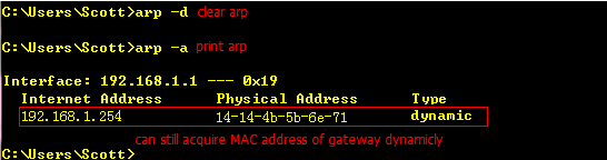
12. Add one static binding entry to IPsource guard table
![]()
13. Confirm that entry has been installed inIP source guard table.
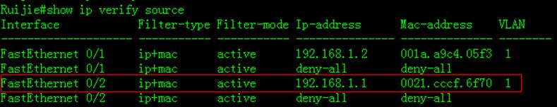
14. Finally , use ping to test connectivitysuccessfully.
2.9.5.5 Port Security
Scenario
Port security:Port security function allows the packets to enter theswitch port by the source MAC address, source MAC+IP address or source IPaddress. You can control the packets by setting the specific MAC addressstatically, static IP+MAC binding or IP binding, or dynamically learninglimited MAC addresses. The port with port security enabled is named as secureport. Only the packets with the source MAC address in the port security addresstable, or IP+MAC binding configured, or IP binding configured, or the learnedMAC address,can join the switch communication, while other packets aredropped.
I. Requirements
1. You can only connect PC1 (IP: 192.168.1.1,MAC:0021.CCCF.6F70) to port F0/1 . If you connect PC1 to other ports, PC1 cannotaccess the network.If other PCs connect port F0/1 , they cannot access thenetwork neither.
2. Port F0/2 can only foward traffic of PC(IP=192.168.1.2, MAC=any) to the network.
II. Network Topology
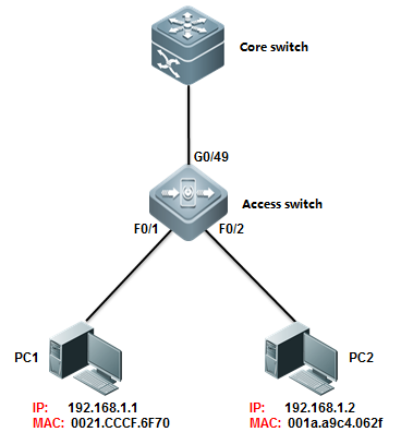
III. Configuration Tips
Enable Port security on port F0/1 and F0/2, then setport security maximun value to 1.
IV. ConfigurationSteps
Configuring Core switch:
1. Assign IP address to Vlan 10 which isuser gateway.
Ruijie(config)#interfacevlan 10
Ruijie(config-if-VLAN10)#ip address 192.168.1.254 255.255.255.0
2. Save configuration
Ruijie(config-if-VLAN10)#end
Ruijie#wr
Configuring Access switch:
1. Enable port security on interface F0/1 to allow the PC ( IP = 192.168.1.1 VLAN=10 , MAC=0021.cccf.6f70 ) to accessnetwork.
Ruijie(config-if-VLAN10)#end
Ruijie#configureterminal
Ruijie(config)#interfacefastEthernet 0/1
Ruijie(config-if-FastEthernet0/1)#switchport port-security binding 0021.CCCF.6F70 vlan 10 192.168.1.1
Ruijie(config-if-FastEthernet0/1)#switchport port-security ------>enable Port Security
Ruijie(config-if-FastEthernet0/1)#exit
2. Enable port security on interface F0/2 toallow the PC ( IP = 192.168.1.1 VLAN=10 , MAC=any ) to access network.
Ruijie(config)#interfacfastEthernet 0/2
Ruijie(config-if-FastEthernet0/2)# switchport port-security binding 192.168.1.2 ------>binding ipaddress 192.168.1.2 to interface f0/2
Ruijie(config-if-FastEthernet0/2)#switchport port-security ------>enable port security
3. Save Configuration
Ruijie(config-if-FastEthernet0/2)#end
Ruijie#write ------>confirmand save
Note:
1. You can configure Port security in threemodes : only MAC address , IP+MAC and only IPaddress
Following example shows how to configurePort Security in" IP+MAC" mode:
Ruijie(config-if-FastEthernet0/1)#switchport port-security binding 0021.CCCF.6F70 vlan 1 192.168.1.1
Following example shows how to configurePort Security in "only IP address" mode:
Ruijie(config-if-FastEthernet0/1)#switchport port-security binding 192.168.1.2
Following example shows how to configurePort Security in "only MAC address" mode:
Ruijie(config-if-FastEthernet0/1)#switchport port-security mac-address 0021.CCCF.6F70
2.When you enable port security on port F0/1in "Only MAC address" mode and bind mac address of PC1 on it , inaddition you don't enable port security on other ports , PC1 can access networkthrough port F0/1 ,but it cannot access network throughother ports.
3.When you enable port security on port F0/1in "Only IP address" or "IP + MAC"mode and bindcorresponding information of PC1 on it , in addition you don't enable portsecurity on other ports ,PC1 can access network through port F0/1 and it can also access network through other ports.
V. Verification
How to display Port security table
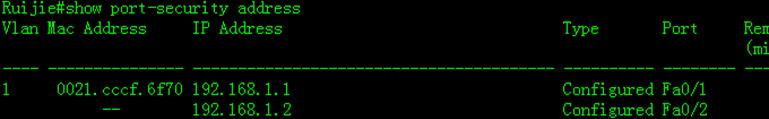
2.9.5.6 Port Protect
Overview
Port Protect:In some application environments, some ports are notrequired to communicate with each other on a device. In such case, frameforwarding is not allowed between the protected ports, no matter the frames areunicast frames, broadcast frames or multicast frames. To achieve this purpose,you can set some ports as protected ports.
Once ports are set as protected ports, they cannotcommunicate with each other. However, protected ports can still communicatewith unprotected ports.
There are two protected port modes: one is to blocklayer 2 forwarding between protected ports but allow layer 3 routing; the otheris to block layer 2 forwarding and layer 3 routing between protected ports. Thefirst mode is by default when both modes are supported.
I. Requirements
As figure shown below, PC1 and PC2 belong toVLAN 10 . PC3 belongs to VLAN 20 . All PC can access to internet ,but theycannot communicate with each other.
II. Network Topology
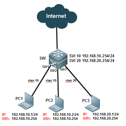
III. Configuration Tips
1. PC1 and PC2 are in the same VLAN 10 and you can enableport protect on ports connected to PC1 and PC2 to prevent PC1 fromcommunicating with PC2.
2. PC3 and PC1,PC2 are in different VLAN and you canenable port protect on ports connected to PC1 ,PC2 and PC3 ,then enable"protected-ports route-deny" feature globally to prevent all PCs fromcommunicating from each other.
IV. ConfigurationSteps
Configuring switch:
Ruijie#configureterminal
Ruijie(config)#vlan10
Ruijie(config-vlan)#vlan20
Ruijie(config-vlan)#exit
Ruijie(config)#interfacevlan 10
Ruijie(config-if-VLAN10)#ip address 192.168.10.254 255.255.255.0
Ruijie(config-if-VLAN10)#interface vlan 20
Ruijie(config-if-VLAN20)#ip address 192.168.20.254 255.255.255.0
Ruijie(config-if-VLAN20)#exit
Ruijie(config)#interfaceGigabitEthernet 0/1
Ruijie(config-if-GigabitEthernet0/1)#switchport access vlan 10
Ruijie(config-if-GigabitEthernet0/1)#switchport protected ------>enable Port protect
Ruijie(config-if-GigabitEthernet0/1)#interface GigabitEthernet 0/2
Ruijie(config-if-GigabitEthernet0/2)#switchport access vlan 10
Ruijie(config-if-GigabitEthernet0/2)#switchport protected ------>enable Portprotect
Ruijie(config-if-GigabitEthernet0/2)#interface GigabitEthernet 0/3
Ruijie(config-if-GigabitEthernet0/3)#switchport access vlan 20
Ruijie(config-if-GigabitEthernet0/3)#switchport protected ------>enable Port protect
Ruijie(config-if-GigabitEthernet0/3)#exit
Ruijie(config)#protected-portsroute-deny ------> Configuringthe Route-denyglobally to blocks Layer 3 traffic between all protected ports.
Ruijie(config)#end
Ruijie#wr
Note:
1) When you configure ports as protectedports, they cannot communicate with each other.However, protected ports can still communicate with unprotected ports.
2) Only S5750E , S8600 , S12000 seriesswitch support "protected-ports route-deny" feature
3) Port protect feature only takes effecton a single Switch .For example, PC1 connects to SWA ,PC2 connects to SWB ,thenconfigure the ports connected to them as protected port , but they can stillcommunicate with each other.
V. Verification
1. How to display port protect status
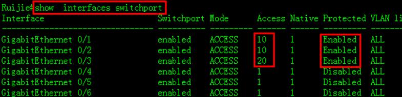
2.9.5.7 AAA
2.9.5.7.1 Authentication
Overview
It verifies whethera user can access, where the Radius protocol or Local can be used. Theauthentication is the method to identify a user before his/her access to thenetwork and network services. The AAA is configured by the definition of anaming list for authentication method and application of it on every interface.The method list defines the authentication type and execution order. Before adefined authentication is executed, the method list must be applied on aspecific interface. The default method list is exceptional. If no other methodlist is defined, the default method list will automatically apply on allinterfaces. The defined method list overwrites the default method list. Allauthentication methods other than the local, line password and allowingauthentication must be defined with AAA.
I. Requirements
1. Administrator wants to setup a Radiusserver to authenticate users at login. The first method is Radius Server andthe fallback is local identity.
2. In case that illegal user breaks in withmethod of exhaustion ,administrator should set login limits and each accounthas 3 times to attempts. Otherwise this account will be locked for 1 hour.(bydefault , limit is 3 attempts and locked time is 15 hours)
II. Network Topology
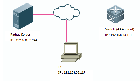
III. Configuration Tips
1. Enable AAA service,then configureSwitch-to-RADIUS-Server Communication.
2. Optimize AAA configuration (AAA lock)
3. Configure Radius Server.
IV. ConfigurationSteps
Configuring switch:
Ruijie#enable
Ruijie#configureterminal
Ruijie(config)#aaanew-model ------>enableAAA
Ruijie(config)#radius-serverhost 192.168.33.244 ------>specify IPaddress of Radius Server
Ruijie(config)#radius-serverkey ruijie ------>speficykey for Radius Server
Ruijie(config)#aaaauthentication login ruijie group radius local ------>defineauthentication login methed list. first method is Radius Server and fallback islocal account.
Ruijie(config)#linevty 0 4
Ruijie(config-line)#loginauthentication ruijie ------>apply AAA authentication on Line VTY
Ruijie(config-line)#exit
Ruijie(config)#usernameadmin password ruijie ------>define local account
Ruijie(config)#enablepassword ruijie ------>set enable password
Ruijie(config)#servicepassword-encryption ------>encrypt all password globally
Ruijie(config)#aaalocal authentication attempts 3 ------>configure therule that swich will lock the account if input the right username but wrongpassword for three times.
Ruijie(config)#aaalocal authentication lockout-time 1 ------>unlock after 1hour
Ruijie(config)#interfacevlan 1
Ruijie(config-if-VLAN1)#ip add 192.168.33.161 255.255.255.0
Ruijie(config-if-VLAN1)#end
Ruijie#write ------>confirm and save configuration
Configuring Radius server:
Configuration of different radius serversvary .See relevant configuration guide.
V. Verification
1. Try to telnet a switch
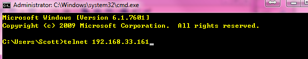
2. Input username and password , then inputenable password to enter privilege mode.
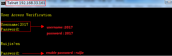
3. Show login user status
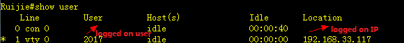
4. If first method (Radius Server)failed,fallback method takes effect.
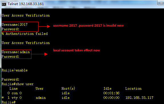
5. If you input right username and wrongpassword three times , your account has been locked.
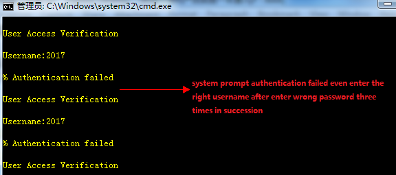
1. Switch enables login authentication onvty line automatically once you use"Ruijie(config)#aaa new-model" command to enable AAA ,requesting user log in with local account.
This example shows how to create a localaccount:
Ruijie(config)#usernameadmin password Ruijie
2. This example shows how to enable aaalogin authentication on console line with use local account
Ruijie(config)#aaanew-model ------>enable AAA
Ruijie(config)#aaaauthentication login ruijie local ------>defineauthentication login method list named ruijie and first method is locolaccount.
Ruijie(config)#usernameadmin password ruijie
Ruijie(config)#lineconsole 0
Ruijie(config-line)#loginauthentication ruijie
Ruijie(config-line)#end
3. This example shows how to use localaccount to be the enable password
Ruijie(config)#aaanew-model ------>enable AAA
Ruijie(config)#aaaauthentication enable default local ------>define authenticationenable method list named ruijie and first method is local account.
Ruijie(config)#usernameadmin password ruijie
4. This example shows how to grant accountprivilege level 15 ,so that this account acquire "#" privilege modeimmediately when logs in
Ruijie(config)#usernameadmin password ruijie
Ruijie(config)#usernameadmin privilege 15
5. This example shows how to log in a switchthrough telnet without any authentication :
Ruijie(config)#aaanew-model
Ruijie(config)#aaaauthentication login default none
Ruijie(config)#linevty 0 4
Ruijie(config-line)#privilegelevel 15
Ruijie(config-line)#end
Note: We don't suggest you to dothis kind of non-authentication
2.9.5.7.2 Athorization
Overview
The AAA authorization enables the administrator tocontrol the user’s use of the services or the rights. After the AAAauthorization service is enabled, the network device configures the usersessions by using the user configuration filestored locally or in the server.After the authorization is completed, the user can only use the servicesallowed in the profile or has the allowed rights.
Authorization Types
Ruijie product supports the following AAA authorizationmethods:
Exec authorizationmethod – the user terminal loggs inthe NAS CLI and is granted the privilegelevel (0-15 level).
Command authorizationmethod – after the user terminal loggs in the NAS CLI, the specific commandsare authorized.
Network authorizationmethod – grant the available service to the user session in the network.
Introduction and limits of privilege 1-15 for Ruijieproduction explain as below :
Level 0: the lowest level ( like Ruijie> ) , onlyseveral commands are granted ----ping , traceroute and enable
Level 1: normal user level ( like Ruijie> ) ,"show" command is added compare with level 0.
Level 2-14 : ordinary administrator (like Ruijie# ),most operations (like configuring , showing , modifying )are allowed , but afew of High-risk operations (like delete. modify files,reload) are forbidden
Level 15: Super administrator (Ruijie#) , highest level, unlimite to do anything
Only TACACS+ supports the command authorization method.For the detailed information, please refer to TACACS+ Configuration
I. Requirements
Tacacs+ server authenticate users when user logs inthrough telnet ,then TACACS+ Server grants user corresponding privilege .
II. Network Topology
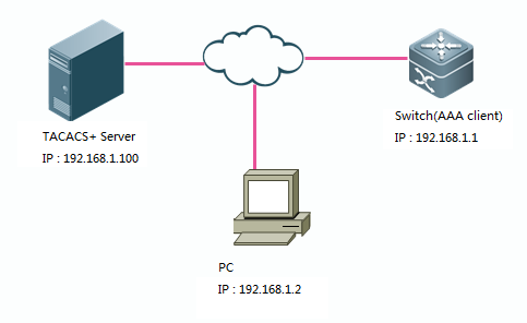
III. Configuration Tips
1. Configure basic route to ensure switch , TACACS+Server and PC can communicate with each other , then configure aaaauthentication
2. Define AAA authorization list and applyAAA authorization list on VTY line
3. Create local username and password
4. Configure TACACS+ Server
IV. Configuration Steps
1. Configure basic route to ensure switch ,TACACS+ Server and PC can communicate with each other , then configure aaaauthentication
See chapterAAA--->Authentication
2. Define AAA authorization list and applyAAA authorization list on VTY line
Ruijie(config)#aaaauthorization exec execauth group tacacs+ local ----->defineauthorization exec method named "execauth" and first method is tacacs,fallback method is local.
Ruijie(config)#linevty 0 4
Ruijie(config-line)#authorizationexec execauth ----->apply authorization method "execauth" on VTY
3. Define local account
Ruijie(config)#usernameruijie password ruijie ----->configure local account :username "ruijie"password "ruijie"
Ruijie(config)#usernameruijie privilege 8 ----->grant account "ruijie" privilege level 8
4. Configure TACACS+
Configuration of different TACACS+ serversvary, See relevant configuration guide.
V. Verification
Verify that the user requires privilege mode(level 8) immediately log in the switch.
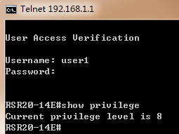
Configuring commandauthorization
I. Requirements
Tacacs+ server authenticates user when user logs inthrough telnet ,and user can use "show" and "ping" commandonly.
II. Network Topology
III. Configuration Tips
1. Configure basic route to ensure switch,TACACS+ Server and PC can communicate with each other , then configure aaaauthentication
2. Configure login authorization
3. Define authorization command method
4. Configure TACACS+ Server
IV. ConfigurationSteps
1. Configure basic route to ensure switch ,TACACS+ Server and PC can communicate with each other , then configure aaaauthentication
See chapter AAA--->Authentication
2. Configure login authorization
Note:
You must assign privilege level 15 to user if user needs toexecute "show run" , otherwise system returns an error message"unknown command"
See ChapterAAA--->Athorization--->Configuring login authorization
3. Define authorization command method
Note:
1) You must specify authorizationmethods for each privilege level from 0 to 15 independently on Ruijie device .
2) By default , switch has appliedauthorization methods "default" on VTY Line , otherwise you mustspeficify authrization methods on VTY line.
This example shows how to speficifyauthroization methods for different privilge level from 0 to 15.
Ruijie(config)#aaaauthorization commands 0 default group tacacs+ local
Ruijie(config)#aaaauthorization commands 1 default group tacacs+ local
Ruijie(config)#aaaauthorization commands 2 default group tacacs+ local
Ruijie(config)#aaaauthorization commands 3 default group tacacs+ local
Ruijie(config)#aaaauthorization commands 4 default group tacacs+ local
Ruijie(config)#aaaauthorization commands 5 default group tacacs+ local
Ruijie(config)#aaaauthorization commands 6 default group tacacs+ local
Ruijie(config)#aaaauthorization commands 7 default group tacacs+ local
Ruijie(config)#aaaauthorization commands 8 default group tacacs+ local
Ruijie(config)#aaaauthorization commands 9 default group tacacs+ local
Ruijie(config)#aaaauthorization commands 10 default group tacacs+ local
Ruijie(config)#aaaauthorization commands 11 default group tacacs+ local
Ruijie(config)#aaaauthorization commands 12 default group tacacs+ local
Ruijie(config)#aaaauthorization commands 13 default group tacacs+ local
Ruijie(config)#aaaauthorization commands 14 default group tacacs+ local
Ruijie(config)#aaaauthorization commands 15 default group tacacs+ local
4. Configure Tacacs server
Configuration of different TACACS+ servers vary .Seerelevant configuration guide.
V. Verification
When you log in, you can execute "showrun" and "ping" command only.
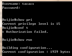
2.9.5.7.3 Accounting
Overview
The AAA accounting function enables you to trace theservices and network resources used by the user. After the accounting functionis enabled, the network access server or router sends the user's networkaccesses to the Radius security server by means of attribute pair. You may usesome analysis software to analyze these data to implement the billing, auditionand tracing function for the user's activities.
Accounting Types
Our product currently supports the following accountingtypes:
Exec Accounting --record the accounting information of entering to and exiting from the CLI ofthe user terminal logged in the NAS CLI.
Command Accounting – record the specific commandexecution information after the user terminal logs in the NAS CLI.
Network Accounting –records the related information on the user session in the network.
Only TACACS+ supports the command accounting function.For the detailed information, please refer to TACACS+ Configuration.
I. Requirements
1. Tacacs+ Server accounts when user logs inand logs out
2. Tacacs+ Server accounts when user enterscommands
II. Network Topology
III. Configuration Tips
1. Configure basic route to ensure switch,TACACS+ Server and PC can communicate with each other , then configure aaalogin authentication
2. Define AAA accounting method and applyAAA authorization method on VTY line
IV. ConfigurationSteps
Tacacs+ Server accounts when user logs inand logs out
1. Configure basic route to ensure switch ,TACACS+ Server and PC can communicate with each other , then configure aaalogin authentication
See ChapterAAA--->Authentication--->Configuring login authentication using Radius
2. Define AAA accounting method and applyAAA authorization method on VTY line
Ruijie(config)#aaaaccounting exec execaccout start-stop group tacacs+ //defineaccounting method named "execaccout"
Ruijie(config)#linevty 0 4
Ruijie(config-line)#accountingexec execaccout
Tacacs+ Server accounts when user enterscommands
1. Configure basic routing and aaa loginparameters
See ChapterAAA--->Authentication--->Configuring login authentication using Radius
2. Define AAA accounting method and applyAAA authorization method on VTY line
Note:
You must specify accountingmethods for each privilege level from 0 to 15 independently on Ruijie device .
This example shows how to speficifyaccounting methods for different privilge level from 0 to 15.
Ruijie(config)#aaaaccounting commands 0 commaccout start-stop group tacacs+ //Definemethod named "commaccout"
Ruijie(config)#aaaaccounting commands 1 commaccout start-stop group tacacs+
Ruijie(config)#aaaaccounting commands 2 commaccout start-stop group tacacs+
Ruijie(config)#aaaaccounting commands 3 commaccout start-stop group tacacs+
Ruijie(config)#aaaaccounting commands 4 commaccout start-stop group tacacs+
Ruijie(config)#aaaaccounting commands 5 commaccout start-stop group tacacs+
Ruijie(config)#aaaaccounting commands 6 commaccout start-stop group tacacs+
Ruijie(config)#aaaaccounting commands 7 commaccout start-stop group tacacs+
Ruijie(config)#aaaaccounting commands 8 commaccout start-stop group tacacs+
Ruijie(config)#aaaaccounting commands 9 commaccout start-stop group tacacs+
Ruijie(config)#aaaaccounting commands 10 commaccout start-stop group tacacs+
Ruijie(config)#aaaaccounting commands 11 commaccout start-stop group tacacs+
Ruijie(config)#aaaaccounting commands 12 commaccout start-stop group tacacs+
Ruijie(config)#aaaaccounting commands 13 commaccout start-stop group tacacs+
Ruijie(config)#aaaaccounting commands 14 commaccout start-stop group tacacs+
Ruijie(config)#aaaaccounting commands 15 commaccout start-stop group tacacs+
Ruijie(config)#linevty 0 4
Ruijie(config-line)#accountingcommands 0 commaccout //apply accounting method "commaccout" on vty line
Ruijie(config-line)#accountingcommands 1 commaccout
Ruijie(config-line)#accountingcommands 2 commaccout
Ruijie(config-line)#accountingcommands 3 commaccout
Ruijie(config-line)#accountingcommands 4 commaccout
Ruijie(config-line)#accountingcommands 5 commaccout
Ruijie(config-line)#accountingcommands 6 commaccout
Ruijie(config-line)#accountingcommands 7 commaccout
Ruijie(config-line)#accountingcommands 8 commaccout
Ruijie(config-line)#accountingcommands 9 commaccout
Ruijie(config-line)#accountingcommands 10 commaccout
Ruijie(config-line)#accountingcommands 11 commaccout
Ruijie(config-line)#accountingcommands 12 commaccout
Ruijie(config-line)#accountingcommands 13 commaccout
Ruijie(config-line)#accountingcommands 14 commaccout
Ruijie(config-line)#accountingcommands 15 commaccout
V. Verification
1. Tacacs+ Server accounts when user logs inand logs out
This example shows the entries about logs inand logs out on cisco ACS :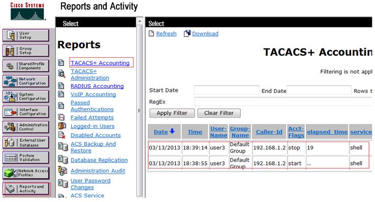
2. Tacacs+ Server accounts when user enters commands
This example shows the entries about commandaccouting on cisco ACS :
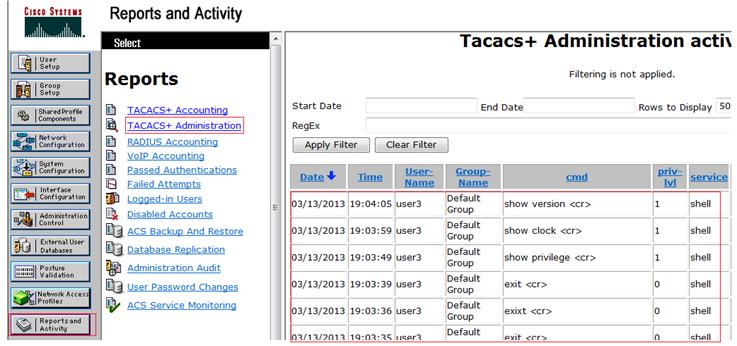
2.9.5.8 ACL
2.9.5.8.1 Anti-virus ACL
Overview
ACL is the shortened form of Access Control List, orAccess List. It is also popularly called firewall, or packet filtering in somedocumentation. ACL controls the messages on the device interface by definingsome rules: Permit or Deny.
According to usage ranges, they can be divided intoACLs and QoS ACLs.By filtering the data streams, you can restrict thecommunication data types in the network and restrict the users of the networkand the device they can use. When data streams pass the switch, ACLs classifyand filter them, that is, check the data streams input from the specifiedinterface and determine whether to permit or deny them according to thematching conditions. To sum up, the security ACL is used to control whichdataflow is allowed to pass through the network device. The QoS policy performspriority classification and processing for the dataflow.
ACLs consist of a series of entries, known as AccessControl Entry (ACE). Each entry specifies its matching condition and behavior.Access list rules can be about the source addresses, destination addresses,upper layer protocols, time-ranges or other information of data flows.
I. Requirements
Administrator wants to deploy anti-virus ACLon Access switch to filter common virus port and enhance network security .
II. Configuration Tips
1. Create extended ACL and define ACE
2. Apply ACL on interfaces
3. Add and delete Access Control Entry(ACE).
III. Network Topology
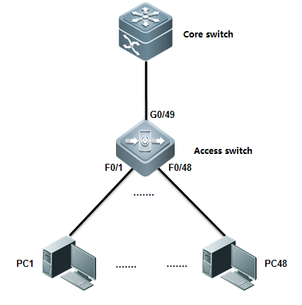
IV. ConfigurationSteps
Configuring Access switch:
1. Create extented ACL and define ACE
Ruijie#configure terminal
Ruijie(config)#ip access-list extended defencevirus ------>createan extended ACL nameddefencevirus
Ruijie(config-ext-nacl)#10 deny tcp any any eq 27665 ------>specify virusports. These information comes from daily practice
Ruijie(config-ext-nacl)#20 deny tcp any any eq 16660
Ruijie(config-ext-nacl)#30 deny tcp any any eq 65000
Ruijie(config-ext-nacl)#40 deny tcp any any eq 33270
Ruijie(config-ext-nacl)#50 deny tcp any any eq 39168
Ruijie(config-ext-nacl)#60 deny tcp any any eq 6711
Ruijie(config-ext-nacl)#70 deny tcp any any eq 6712
Ruijie(config-ext-nacl)#80 deny tcp any any eq 6776
Ruijie(config-ext-nacl)#90 deny tcp any any eq 6669
Ruijie(config-ext-nacl)#100 deny tcp any any eq 2222
Ruijie(config-ext-nacl)#110 deny tcp any any eq 7000
Ruijie(config-ext-nacl)#120 deny tcp any any eq 135
Ruijie(config-ext-nacl)#130 deny tcp any any eq 136
Ruijie(config-ext-nacl)#140 deny tcp any any eq 137
Ruijie(config-ext-nacl)#150 deny tcp any any eq 138
Ruijie(config-ext-nacl)#160 deny tcp any any eq 139
Ruijie(config-ext-nacl)#170 deny tcp any any eq 445
Ruijie(config-ext-nacl)#180 deny tcp any any eq 4444
Ruijie(config-ext-nacl)#190 deny tcp any any eq 5554
Ruijie(config-ext-nacl)#200 deny tcp any any eq 9996
Ruijie(config-ext-nacl)#210 deny tcp any any eq 3332
Ruijie(config-ext-nacl)#220 deny tcp any any eq 1068
Ruijie(config-ext-nacl)#230 deny tcp any any eq 455
Ruijie(config-ext-nacl)#240 deny udp any any eq 31335
Ruijie(config-ext-nacl)#250 deny udp any any eq 27444
Ruijie(config-ext-nacl)#260 deny udp any any eq 135
Ruijie(config-ext-nacl)#270 deny udp any any eq 136
Ruijie(config-ext-nacl)#280 deny udp any any eq netbios-ns
Ruijie(config-ext-nacl)#290 deny udp any any eq netbios-dgm
Ruijie(config-ext-nacl)#300 deny udp any any eq netbios-ss
Ruijie(config-ext-nacl)#310 deny udp any any eq 445
Ruijie(config-ext-nacl)#320 deny udp any any eq 4444
Ruijie(config-ext-nacl)#330 permit ip any any
Ruijie(config-ext-nacl)#exit
2. Apply ACL on interfaces
Ruijie(config)#interfacerange fastEthernet 0/1-24
Ruijie(config-if-range)#ipaccess-group defencevirus in
3. ACE Add and delete ACE
Ruijie(config-ext-nacl)#15deny tcp any any eq 707 ------>insert No.15 ACE between No.10and No.20 .
Ruijie(config-ext-nacl)#no15 ------>delete No.15
Note:ACL enforces in hardware , so ACL is notapplied if there are insufficient hardware resource available .
V. Verification
How to display ACL configuration and status
Ruijie(config)#showip access-group ------>where ACL apply
ipaccess-group defencevirus in
AppliedOn interface GigabitEthernet 0/1.
Ruijie#show access-lists ------>show ACLconfiguration
ipaccess-list extended defencevirus
10deny tcp any any eq 27665
15deny tcp any any eq 707
20deny tcp any any eq 16660
30deny tcp any any eq 65000
40deny tcp any any eq 33270
50deny tcp any any eq 39168
60deny tcp any any eq 6711
70deny tcp any any eq 6712
80deny tcp any any eq 6776
90deny tcp any any eq 6669
100deny tcp any any eq 2222
110deny tcp any any eq 7000
120deny tcp any any eq 135
130deny tcp any any eq 136
140deny tcp any any eq 137
150deny tcp any any eq 138
160deny tcp any any eq 139
170deny tcp any any eq 445
180deny tcp any any eq 4444
190deny tcp any any eq 5554
200deny tcp any any eq 9996
210deny tcp any any eq 3332
220deny tcp any any eq 1068
230deny tcp any any eq 455
240deny udp any any eq 31335
250deny udp any any eq 27444
260deny udp any any eq 135
270deny udp any any eq 136
280deny udp any any eq netbios-ns
290deny udp any any eq netbios-dgm
300deny udp any any eq netbios-ss
310deny udp any any eq 445
320deny udp any any eq 4444
330permit ip any any
6. Configuration Script
ipaccess-list extended defencevirus
10deny tcp any any eq 27665
20deny tcp any any eq 16660
30deny tcp any any eq 65000
40deny tcp any any eq 33270
50deny tcp any any eq 39168
60deny tcp any any eq 6711
70deny tcp any any eq 6712
80deny tcp any any eq 6776
90deny tcp any any eq 6669
100deny tcp any any eq 2222
110deny tcp any any eq 7000
120deny tcp any any eq 135
130deny tcp any any eq 136
140deny tcp any any eq 137
150deny tcp any any eq 138
160deny tcp any any eq 139
170deny tcp any any eq 445
180deny tcp any any eq 4444
190deny tcp any any eq 5554
200deny tcp any any eq 9996
210deny tcp any any eq 3332
220deny tcp any any eq 1068
230deny tcp any any eq 455
240deny udp any any eq 31335
250deny udp any any eq 27444
260deny udp any any eq 135
270deny udp any any eq 136
280deny udp any any eq netbios-ns
290deny udp any any eq netbios-dgm
300deny udp any any eq netbios-ss
310deny udp any any eq 445
320deny udp any any eq 4444
330 rmit ipany any
!
2.9.5.8.2 TCP Unidirectional control ACL
Overview
By filtering the packets of TCP SYN initialization, youcan block the TCP traffic from stations in lower security zone to that inhigher security zone. As per the process of TCP connection, the first TCPinitialization packet in which the SYN bit is set to 1 and the ACK bit is setto 0. Therefore,you can use ACL to block this kind of packet to filter thesubsequence TCP traffic from lower security zone to higher security zone in theone-way direction
This feature is especially suitable for Servers , suchas FTP , WEB ,that provides services for internet users . Users from internetis allowed to visit these servers , but servers are forbidden to visit theinternet.
This feature of Access Lists don't have anyimpact on traffic of ICMP and UDP
I. Requirements
There're two subnets in the network : subnetA 192.168.200.0/24 and subnet B 192.168.100.0/24.Stations in subnet A can visitstations in subnet B through TCP , but stations in subnet B cannot visitstations in subnet B through TCP.
II. Configuration Tips
ACL can block TCP traffic by filtering the TCP packetin which SYN bit is 1 and ACK bit is 0.
III. Network Topology
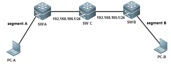
IV. ConfigurationSteps
Scheme 1: Apply ACL on Switch B
Configuring Switch B:
Ruijie#configure terminal
Ruijie(config)#ip access-list extended 101 ------>create extendedACL 101
Ruijie(config-ext-nacl)#deny tcp 192.168.100.0 0.0.0.255 192.168.200.0 0.0.0.255 match-all syn ------>denyTCP packets in which Syn bit is 1 and other bit is 0(includes ACK bit)
Ruijie(config-ext-nacl)#permit ip any any ------>permit anyother traffic
Ruijie(config-ext-nacl)#exit
Ruijie(config)#interface gigabitEthernet 3/2
Ruijie(config-if)#ip access-group 101 in ------>apply ACL 101on the interface in the input direction
Ruijie(config-if)#end
Ruijie#wr
Scheme 2: Apply ACL on Switch A
Ruijie#configure terminal
Ruijie(config)#ip access-list extended 101 ------>create extendedACL 101
Ruijie(config-ext-nacl)# deny tcp 192.168.100.0 0.0.0.255 192.168.200.0 0.0.0.255 match-all syn ------>denyTCP packets in which Syn bit is 1 and other bit is 0(includes ACK bit)
Ruijie(config-ext-nacl)#permit ip any any ------>permit anyother traffic
Ruijie(config-ext-nacl)#exit
Ruijie(config)#interface VLAN 100
Ruijie(config-if-VLAN100)#ip access-group 101 out ------>apply ACL 101 on the SVI in theoutput direction
Ruijie(config-if)#end
Ruijie#wr
V. Verification
How to display ACL configuration:
Ruijie#show access-lists 101
ipaccess-list extended 101
10deny tcp 192.168.100.0 0.0.0.255 192.168.200.0 0.0.0.255 match-all syn
20permit ip any any
Verify that stations in subnet B cannotinitialize TCP connection to stations in subnet A ,but they can stillcommmunicate with each other on ICMP and UDP
2.9.5.8.3 Time-based ACL
I. Requirements
Filter the traffic from stations in Intranet toInternet during office hour(from 9:00 am to 12:00 am and 14:00 pm to 18:00 pm)and permit this traffic in any other time.
Stations in Intranet can communicate with each otherunlimited.
II. Network Topology
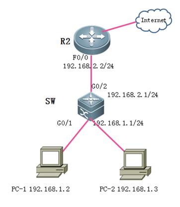
III. Configuration Tips
1. Correct switch clock,becasuetime-based ACL refers to swich clock.
2. When define a time-range , you cannot define atime-range that across 00:00. For example ,If you want to define a time-rangefrom 10:00 pm to 7:00 am :
Ruijie(config)#time-rangeaaa
Ruijie(config-time-range)#periodicdaily 0:00 to 7:00
Ruijie(config-time-range)#periodicdaily 22:00 to 23:59
3. Both standard and extend ACL supporttime-range ACL
IV. ConfigurationSteps
1. Correct switch clock
Ruijie>enable
Ruijie(config)#clocktimezone beijing 8 -----> set timezone to UTC+8
Ruijie(config)#exit
Ruijie#clockset 10:00:00 12 1 2012 -----> hour:minute:second month day year
2. Define time-range
Ruijie(config)#time-rangework ----->define a time-range named work
Ruijie(config-time-range)#periodicdaily 9:00 to 12:30
Ruijie(config-time-range)#periodicdaily 14:00 to 18:30
Ruijie(config-time-range)#exit
3. Create a ACL and define ACE
Ruijie(config)#ipaccess-list extended 100
Ruijie(config-ext-nacl)#5permit ip 192.168.1.0 0.0.0.255 192.168.0.0 0.0.255.255 ----->permitany traffic between stations in intranet
Ruijie(config-ext-nacl)#10deny ip 192.168.1.0 0.0.0.255 any time-range work ----->deny any trafficfrom 192.168.1.0/24 to Internet during work time
Ruijie(config-ext-nacl)#20permit ip any any ----->permit any other traffic(you must configure thiscommand , because there's an implicit deny any in the end)
Ruijie(config-ext-nacl)#exit
4. Apply ACL on interface
Ruijie(config)#interfaceGigabitEthernet 0/1
Ruijie(config-if-GigabitEthernet0/1)#ip access-group 100 in ----->apply ACL 100 on interfaceconnected to intranet
5. Save configuration
Ruijie(config-if-GigabitEthernet0/1)#end
Ruijie#write
V. Verification
1) How to display system clock
Ruijie#showclock
10:14:01beijing Sat, Dec 1, 2012
2) How to display ACL configuration
Ruijie#showaccess-lists
ipaccess-list extended 100
5 permit ip 192.168.1.0 0.0.0.255 192.168.0.0 0.0.255.255
10deny ip 192.168.1.0 0.0.0.255 any time-range work (active) ----->redmark "active" indicates that it is office time now
20permit ip any any
3) How to display ACL status
Ruijie#showip access-group
ipaccess-group 100 in
AppliedOn interface GigabitEthernet 0/1.
2.9.6 QoS
2.9.6.1 Working Principles and Basic Configuration
QoSon Switches
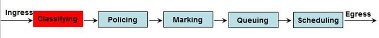
Note: The preceding figureshows the QoS data processing process. The following describes the functions ofeach step.
1. Classifying
Classifythe incoming data traffic into non-IP data traffic and IP data traffic andlabels the two data traffic types with different differentiated services codepoint (DSCP) values.
DSCPlabeling for non-IP data traffic
Method1: On the ingress interface, configure the policy mapping.
Mac access-list extended mac_acl
permit …
class-map mac_class
match access-group mac_acl
policy-map mac_policy
class mac_class
set cos 6
interface Gi0/1
service-policy input mac_policy
Theobtained CoS information is mapped based on the CoS-to-DSCP MAP table.
In thisway, the data traffic is labeled with DSCP values.
Method2: Enable the port trust mode CoS on the ingress port. If the L2 header of thepacket
interface Gi0/1
mls qos trust cos
containsCoS, the CoS value (contained in the VLAN Tag field) is obtained from thepacket.
Theobtained CoS information is mapped based on the CoS-to-DSCP MAP table.
In thisway, the data traffic is labeled with SDCP values.
Method3: Enable the port trust mode CoS on the ingress port. If the L2 header of thepacket
interface Gi0/1
mls qos trust cos
mls qos cos 6
does notcontain CoS, obtain the CoS value of the packet according to the default CoSvalue of the ingress interface.
Theobtained CoS information is mapped based on the CoS-to-DSCP MAP table.
In thisway, the data traffic is labeled with DSCP values.
Note
1. Theabove criteria 2, 3 take effect only when the QoS trust mode of the port isenabled. Enabling the QoS trust mode of a port does not mean getting the QoSinformation directly from the message or the input port of the message withoutanalyzing the message contents.
2. Theabove three criteria may apply simultaneously on the same port. In this case,they will take effect according to the sequence 1, then 2 and then 3. In otherwords, the ACLs work first for the classifying operation. When it fails, thecriteria 2 will be used, and so on. Here, if the QoS trust mode of the port isenabled, criteria 2 and 3 will be used to get the QoS information directly fromthe message or the port; otherwise, default DSCP value 0 will be assigned forthe messages failing the classifying operation.
DSCPlabeling for IP data traffic
Method1: On the ingress interface, use the mapping table based on the applied policy.
Method2: Enable the port trust mode IP precedence on the ingress port. Obtain the IPprecedence information from the IP packet header.
Theobtained IP precedence information is mapped based on the ip-prec-dscp MAPtable.
In thisway, the data traffic is labeled with DSCP values.
Method3: Enable the port trust mode COS on the ingress interface to obtain the COSinformation of the packet. There are two situations as follows:
1. TheL2 header does not contain COS. In this case, the COS information of the packetis obtained based on the default COS of the ingress interface.
2. TheL2 header contains COS. In this case, the COS information of the packet isdirectly obtained from the L2 header.
Theobtained CoS information is mapped based on the CoS-DSCP MAP table.
In thisway, the data traffic is labeled with DSCP values.
Method4: Enable the port trust mode DSCP on the ingress port. Obtain the DSCPinformation from the IP packet header.
2. Summary
Theincoming data traffic is classified into non-IP data traffic and IP datatraffic.
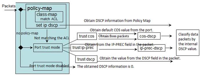
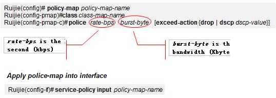
Note:When one mapping policy is applied on multiple ports, the rate restrictionbandwidth of each port is independent from each other.
3.Marking:
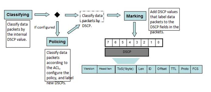
TheDSCP-to-CoS Map table and CoS-to-Queue Map table are the default ones on thedevice.
TheCoS-Map table is a default mapping table of CoS values and queues.

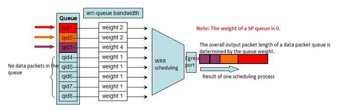
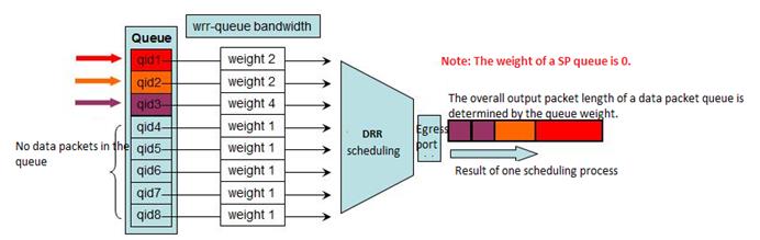
Configurationmethod:
1.Select the output queue scheduling algorithm.
2.Configure the scheduling weight for the output queue.
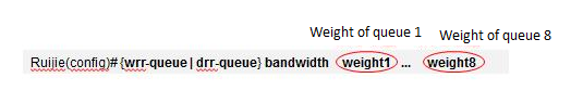
When theweight (WRR/DRR) is set to 0, SP scheduling is used for the queue. Thefollowing is an example describing how to configure the SP+DRR or SP+WRRscheduling algorithm.
SP+DRR/SP+WRRScheduling Configuration on Switch 11x
The SPgroup queue features the top priority. The DDR group queue is scheduled onlywhen the SP queue is empty.
Grouptype SP0 SP0 DRR0 DRR0 DRR0 SP1 DRR1 DRR1
Queue 0 1 2 3 4 5 6 7
Weight 0 0 1 2 3 0 1 1
Differentfrom that on type-A switches, the scheduling sequence is SP1, SP0, and otherDDR queues in weight sequence.
2.9.6.2 Rate Limit on Ports
Scenario
The rate limit featuresupports only unitary rate limit on a port. The function does not differentiatethe rate limit by traffic type. It is similar to fixed bandwidth allocation tothe port. The method features simple configuration and unitary control.
Function Overview
There are two methods ofimplementing rate limit on a port of a switch.
1. Create a QoS PolicyMap table. Apply the Policy Maps table on the in/out direction of the port toimplement rate limit in the in/out direction.
2. Apply the rate limitinput/output policy on the port for rate limit in the in/out direction.
Both the QoS rate limitmethod and the rate limit policy are realized in the hardware level with thetwo rate three color leaky bucket scheduling (CIR average rate + CBS burstlength). The rate limit granule is 64 Kbps and the precision approximatelyequals packet length / (packet length + interframe spacing + CRC), and theEthernet interframe spacing and CRC cost is 20 bytes.
The test proves that theshorter a packet is, the lower the precision is. For example, the rate limitprecision for packets in the length of 64 bytes is lower than that of 1518bytes.
Generally, rate limitusing the policy map method is carried out based on the leaky bucket algorithmand the rate limit policy is carried out by the register on the port. However,on Ruijie products, both methods are carried out based on the leaky bucketalgorithm and feature equal effect.
The major differencebetween the two methods are that the policy map method supports correlationwith the ACL and can implement rate limit for packets of certain traffic types (for example, HTTP traffic and traffic of users on the xx networksegment), featuring flexible control. The rate limit policy supports onlyunitary rate limit on a port. The function does not differentiate the ratelimit by traffic type, featuring unitary control.
The N18000 series,S8600E, and S7800E support the bi-directional rate limit policy andbi-directional policy map method for rate limit.
I. NetworkingRequirements
The branches of anorganization connect to the core switch through MSTP links and share unifiedInternet access egresses. As the branches vary in sizes and scales, the networkadministrator wants to specify uplink and downlink rates for the port of eachbranch.
II. Network Topology
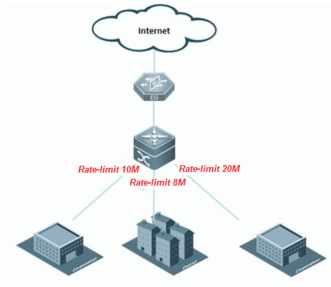
III. ConfigurationTips
1. Use the policy mapmethod to limit the rate.
1) Use the ACL toclassify the traffic.
2). Configure a class maptable to correlate to the ACL.
3. Configure a policy maptable to correlate to the class map table and set the traffic policy.
4. Invoke the policy maptable on the port.
2. Use the rate limitpolicy for rate control.
1. Apply the rate limitpolicy on the port.
IV. ConfigurationSteps
1. Use the ACL toclassify the traffic.
------>Note:
1. The rate limit commandconfigures not only the rate limits but also the burst rate. The burst rate canbe configured in the following way:
1) The value range of theburst rate is (2, 4, 8, 16, 32, 6...1024, 2*1024, 4*1024, 16*1024).
2) A minimum of 200 msbuffering capacity is recommended for the leaky bucket. That is, that minimalrecommended value is (CIR/8)*200ms, or Rate limit/40.
3) The burst rate canincrease the leaky bucket size for unexpected services, such as video and filetransmission, and thereby enhance QoS burst tolerance.
Considering the abovethree principles, a 2x most proximate to the value of Rate limit/10is selected.
2. Configure the ratelimit policy for rate control on the port.
1. The rate limit commandconfigures not only the rate limits but also the burst rate. The burst rate canbe configured in the following way:
1). The value range of theburst rate is (2, 4, 8, 16, 32, 6...1024, 2*1024, 4*1024, 16*1024).
2). A minimum of 200 msbuffering capacity is recommended for the leaky bucket. That is, that minimalrecommended value is (CIR/8)*200ms, or Rate limit/40.
3) The burst rate canincrease the leaky bucket size for unexpected services, such as video and filetransmission, and thereby enhance QoS burst tolerance.
Considering the abovethree principles, a 2x most proximate to the value of Rate limit/10is selected.
Command description:
Input|output: indicateswhether the input or output traffic rate is to be limited.
kbps: indicates the upperrate limit in the unit of kbps.
burst-bytes: indicatesthe burst traffic size (leaky bucket size) in the unit of Kbyte.
V. Verification
1. Run the Ruijie#showpolicy-map interface gigabitEthernet 1/1 command to check the QoS policyinvoked by the port.
2. Run the Ruijie#showmls qos rate-limit command to view the rate limit policy of the port.
2.9.7 Reliability
2.9.7.1 BFD
Overview
BFD can detect linkstatus in micro second and would besuitable for the scenario that requires sensitive delay , less packet loss ,like financial industry , ISP , medical industry .
For example , OSPF converge time would be at lease 40sto 50s which is intolerable for intolerability , but if cooperate OSPF with BFD, the converge time would be less than 1s.
BFD can also operate with many other protocol likestatic route , VRRP , PBR etc.
BFD:(BidirectionalForwarding Detection)provides low-overhead, short-duration detection oftheconnectivity in the forwarding path between adjacent routers.The fast detectionof failures in the forwarding path speeds up enabling the backup forwardingpath and improves the network performance. The BFD detection mechanism isindependent from the applied interface media type, the encapsulation format madthe associated upper-layer protocols such as OSPF, BGP, RIP.The BFD establishesa session between adjacent routers enables the route protocols to re-calculatethe route table by rapidly sending the detection fault to the running routeprotocols and decreases the network convergence time sharply. The BFD itselfcannot discover the neighbors, so it needs the upper-layer protocols to notifythe neighbors of which the session is established.
BFD Packet format
BFD uses UDP packets and there're 2 typespackets---control and echo.
If one end receives the version 0 control packets fromthe peer, the default version 1 will automatically switch to version 0 toestablish the BFD session. You can use the show bfd neighborscommand to viewthe version member.
Format of BFP control packets(version 1) is shown asbelow:
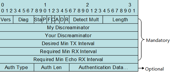
Vers:BFD protocolversion. Currently, the value is 1
Diag:the cause oflatest switchover
Sta:Local statusof the BFD
P:When aparameter changes, the sender places this flag in a BFD packet, to which thereceiver must immediately respond.
F:The packetmust have the F flag set for responding to the packet with the P flag set.
C:Forward/controlseparation flag. Once this flag isset, the change of the control plane does notaffect the BFD. For example, if the control plane deploys OSPF, the BFDcontinues with link status detection when OSPF restarts or performs a gracefulrestart (GR).
A:Authenticationflag. If this flag isset, sessions need to be authenticated.
D:Query demandflag. If this flag is set, the sender expects to detect links in the querymode.
R:Reserved Flag
Detect Mult:Detectiontimeout multiples. This flag is used by the detector to compute the timeoutduration.
Length:Packet length
My Discreaminator:Discriminator used by the BFD session to connect to thelocal end
Your Discreaminator:Discriminator used by the BFD session to connect to theremote end
Desired Min Tx Interval:Minimum BFD packet sending interval supported by thelocal end
Required Min RX Interval:Minimum BFD packet receiving interval supported by thelocal end
Required Min Echo RX Interval:Minimum echo packet receiving interval supported by thelocal end. If the local end does not
support the echo function, set the value to0.
Auth Type:Authenticationtypes, including
Simple Password
Keyed MD5
Meticulous Keyed MD5
Keyed SHA1
Meticulous Keyed SHA1
Auth Length : Authentication data length
Authentication Data:Authentication data area
The UDP port number for control packet is3784.
The difference between DLDP and BFD:
1. You must apply DLDP on ethernet port ,and you can apply BFD between any two hosts regardless port type.
2. DLDP utilizes ICMP ,and BFD utilizes BFDmechanism.
3. You can apply DLDP on one end beceasueDLDP is a unidirection detection , but you must apply BFD on both ends becasueBFD is a bidirection detection
4. DLDP bases on port ,and when DLDPdetection failed , DLDP shuts the port down (for example , SVI , Layer 3 port)and remove all the routes that is related to the port. BFD bases on pairs ,when BFD detection failed , BFD controls only the specific route.
BFD with static route
I. Requirements
As figure shown below, SW1 connects to SW2 with twoequal access to two different service providers so there're two static routesto the same detination. The static route to ISP-B is a floating route and it isthe backup path. Use BFD to detect link availbility.
II. Network Topology
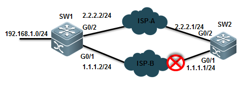
III. Configuration Tips
Associate static route with BFD
IV. ConfigurationSteps
Configuring SW1
1. Assign IP address and configure floatingstatic route
SWA(config)#interfacegigabitEthernet 0/1
SWA(config-GigabitEthernet0/1)#no switchport
SWA(config-GigabitEthernet0/1)#ip address 1.1.1.2 255.255.255.0
SWA(config)#interfacegigabitEthernet 0/2
SWA(config-GigabitEthernet0/2)#no switchport
SWA(config-GigabitEthernet0/2)#ip address 2.2.2.2 255.255.255.0
SWA(config)#iproute 0.0.0.0 0.0.0.0 g0/1 1.1.1.1 ------>when associatestatic route with BFD , you must configure outgoing interface and next hop atthe same time . The next hop ip address must be the source ip address of theBFD peer.
SWA(config)#iproute 0.0.0.0 0.0.0.0 2.2.2.1 200 ------>floating staticroute
2. Assiciate BFD with static route
SWA(config)#interfacegigabitEthernet 0/1
SWA(config-GigabitEthernet0/1)#bfd interval 500 min_rx 500 multiplier 3 ------>set BFD timeparameter and enable BFD on the interface. We suggest you to use 500/500/3value . BFD sends a detection packet every 500ms and is timeout when BFDdoesn't receive replies three times.
SWA(config-GigabitEthernet0/1)#no bfd echo ------>by default BFD echo mode is on .when a FW ordevices of other vendors connect between two BFD peers , the devices canpossible filter BFD packets ,then BFD will fail to build connections . Wesuggest you to disable BFD echo.
SWA(config)#iproute static bfd GigabitEthernet 0/1 1.1.1.1 source 1.1.1.2 ------>associate BFD with static route
Configuring SW2:
1. Assign IP address and configure floatingstatic route
SWB(config)#interfacegigabitEthernet 0/1
SWB(config-GigabitEthernet0/1)#ip address 1.1.1.1 255.255.255.0
SWB(config)#interfacegigabitEthernet 0/2
SWB(config-GigabitEthernet0/2)#ip address 2.2.2.1 255.255.255.0
SWB(config)#iproute 192.168.1.0 255.255.255.0 1.1.1.2
SWB(config)#iproute 192.168.1.0 255.255.255.0 2.2.2.2 200
2. Assiciate BFD with static route
SWB(config)#interfacegigabitEthernet 0/1
SWB(config-GigabitEthernet0/1)#bfd interval 500 min_rx 500 multiplier 3
SWB(config-GigabitEthernet0/1)#no bfd echo
SWB(config)#iproute static bfd GigabitEthernet 0/1 1.1.1.2 source 1.1.1.1
V. Verification
1. How to display BFD neighbor status
R1#shbfd nei
OurAddr NeighAddr LD/RD RH/RS Holdown(mult) State Int
1.1.1.2 1.1.1.1 2/1 Up 0(5 ) Up GigabitEthernet 0/1
2. Use "show ip route" EXECcommand to display IP route table
3. Use "traceroute" to confirmthat SW1 selects ISP-A
4. Shutdown port G0/1 on SW2 to simulate thescenario ISP-A is down , then use "traceroute" to confirm that SW1selects ISP-B
5. How to display detail BFD neighborinformation
Ruijie#show bfd neighbors details
OurAddr NeighAddr LD/RD RH/RS Holdown(mult) State Int
1.1.1.2 1.1.1.1 1/2 Up 532 (3 ) Up GigabitEthernet 0/1
LocalDiag: 0, Demand mode: 0, Poll bit: 0
MinTxInt:200000, MinRxInt: 200000, Multiplier: 5
ReceivedMinRxInt: 50000, Received Multiplier: 3
Holdown(hits): 600(22), Hello (hits): 200(84453)
RxCount: 49824, Rx Interval (ms) min/max/avg: 208/440/332
TxCount: 84488, Tx Interval (ms) min/max/avg: 152/248/196
Registeredprotocols: route
Uptime:02:18:49
Lastpacket: Version: 1 - Diagnostic: 0
IHear You bit: 1 - Demand bit: 0
Pollbit: 0 - Final bit: 0
Multiplier:3 - Length: 24
MyDiscr.: 2 - Your Discr.: 1
Mintx interval: 50000 - Min rx interval: 50000
Relevant information
| Field | Description |
| OurAddr | IP address for the session on the local end |
| NeighAddr | IP address for the adjacent session |
| LD/RD | Session discriminator on the local and peer end |
| RH/RS | Current status of the session peer end |
| Holdown(mult) | Time of not receiving the Hello packets on the local end and the detected timeout time of the session |
| State | Current session state |
| Int | Interface number for the session |
| Session state is UP and using echo function with 50 ms interval | Whether the session is in echo mode and the interval of sending frames. This information is shown only in the echo mode |
| Local Diag | Diagnostic information of the session |
| Demand mode | Whether the demand mode is enabled or not |
| Poll bit | Whether the session configuration is modified |
| MinTxInt | Minimum sending interval of the session on the local End |
| MinRxInt | Minimum receiving interval of the session on the local end |
| Multiplier | Timeout times detected on the local end |
| Received MinRxInt | Minimum sending interval of the session on the peer end |
| Received Multiplier | Timeout times detected on the peer end |
| Holdown (hits) | Session detection time and the detected timeout times |
| Hello (hits) | Minimum interval of receiving the Hello packet after the session negotiation |
| Rx Count | Count of BFD packets received on the local end |
| Rx Interval (ms) min/max/avg | Minimum/maximum/average interval of receiving the session on the local end |
| Tx Count | Count of BFD packets sent on the local end |
| Tx Interval (ms) min/max/avg | Minimum/maximum/average interval of sending the session on the local end |
| Registered protocols | Type of protocol registered to the session |
| Uptime | Time of keeping the session UP |
| Last packet | Last BFD packet received on the local end |
BFD with OSPF
I. Requirements
Administrator connects a L2 Switch betweenSwitch A and Switch B and both SW1 and SWB are running OSPF. Administratorwants to associate OSPF with BFD to ensure a fast OSPF convergence when thelink between SWB and switch is down.
II. Network Topology
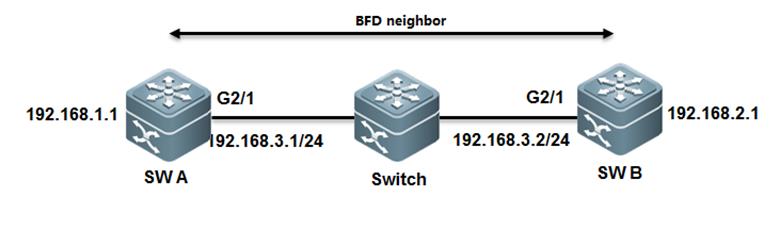
III. Configuration Tips
1. Assign IP address and configure OSPF
2. Associate BFD with OSPF
IV. ConfigurationSteps
Configuring SWA:
1. Assign IP address and configure OSPF
SWA(config)#interfacegigabitEthernet 2/1
SWA(config-GigabitEthernet2/1)#ip address 192.168.3.1 255.255.255.0
SWA(config)#interfacegigabitEthernet 1/1
SWA(config-GigabitEthernet1/1)#ip address 192.168.1.1 255.255.255.0
SWA(config-router)#routerospf 123
SWA(config-router)#network192.168.3.0 0.0.0.255 area 0
SWA(config-router)#network192.168.1.0 0.0.0.255 area 0
2. Associate BFD with OSPF
SWA(config)#interfacegigabitEthernet 2/1
SWA(config-GigabitEthernet2/1)#bfd interval 500 min_rx 500 multiplier 3 ------>set BFD timeparameter and enable BFD on the interface. We suggest you to use 500/500/3value . BFD sends a detection packet every 500ms and is timeout when BFDdoesn't receive replies three times.
SWA(config-GigabitEthernet2/1)#no bfd echo ------>by default BFD echo mode is on .when a FW or devicesof other vendors connect between two BFD peers , the devices can possiblefilter BFD packets ,then BFD will fail to build connections . We suggest youto disable BFD echo.
SWA(config-router)# router ospf 123
SWA(config-router)# bfd all-interfaces ------>associate BFD with OSPF
Configuring SWB:
1. Assign IP address and configure OSPF
SWB(config)#interfacegigabitEthernet 2/1
SWB(config-GigabitEthernet2/1)#ip address 192.168.3.2 255.255.255.0
SWB(config)#interfacegigabitEthernet 1/1
SWB(config-GigabitEthernet1/1)#ip address 192.168.2.1 255.255.255.0
SWB(config-router)# router ospf 123
SWB(config-router)#network192.168.3.0 0.0.0.255 area 0
SWB(config-router)#network192.168.2.0 0.0.0.255 area 0
2. Associate BFD with OSPF
SWB(config)#interfacegigabitEthernet 2/1
SWB(config-GigabitEthernet2/1)#bfd interval 500 min_rx 500 multiplier 3
SWB(config-GigabitEthernet2/1)#no bfd echo
SWB(config-router)#routerospf 123
SWB(config-router)#bfdall-interfaces
V. Verification
1. How to display BFD neighbor status
Ruijie#show bfd neighbors
OurAddr NeighAddr LD/RD RH/RS Holdown(mult) State Int
192.168.3.1 192.168.3.2 1/2 Up 532 (3 ) Up G2/1
2. How to display detail BFD neighborinformation
Ruijie#show bfd neighbors details
OurAddr NeighAddr LD/RD RH/RS Holdown(mult) State Int
192.168.3.1 192.168.3.2 1/2 Up 532 (3 ) Up Ge2/1
LocalDiag: 0, Demand mode: 0, Poll bit: 0
MinTxInt:200000, MinRxInt: 200000, Multiplier: 5
ReceivedMinRxInt: 50000, Received Multiplier: 3
Holdown(hits): 600(22), Hello (hits): 200(84453)
RxCount: 49824, Rx Interval (ms) min/max/avg: 208/440/332
TxCount: 84488, Tx Interval (ms) min/max/avg: 152/248/196
Registeredprotocols: OSPF
Uptime:02:18:49
Lastpacket: Version: 1 - Diagnostic: 0
IHear You bit: 1 - Demand bit: 0
Pollbit: 0 - Final bit: 0
Multiplier:3 - Length: 24
MyDiscr.: 2 - Your Discr.: 1
Mintx interval: 50000 - Min rx interval: 50000
Relevant information
| Field | Description |
| OurAddr | IP address for the session on the local end |
| NeighAddr | IP address for the adjacent session |
| LD/RD | Session discriminator on the local and peer end |
| RH/RS | Current status of the session peer end |
| Holdown(mult) | Time of not receiving the Hello packets on the local end and the detected timeout time of the session |
| State | Current session state |
| Int | Interface number for the session |
| Session state is UP and using echo function with 50 ms interval | Whether the session is in echo mode and the interval of sending frames. This information is shown only in the echo mode |
| Local Diag | Diagnostic information of the session |
| Demand mode | Whether the demand mode is enabled or not |
| Poll bit | Whether the session configuration is modified |
| MinTxInt | Minimum sending interval of the session on the local End |
| MinRxInt | Minimum receiving interval of the session on the local end |
| Multiplier | Timeout times detected on the local end |
| Received MinRxInt | Minimum sending interval of the session on the peer end |
| Received Multiplier | Timeout times detected on the peer end |
| Holdown (hits) | Session detection time and the detected timeout times |
| Hello (hits) | Minimum interval of receiving the Hello packet after the session negotiation |
| Rx Count | Count of BFD packets received on the local end |
| Rx Interval (ms) min/max/avg | Minimum/maximum/average interval of receiving the session on the local end |
| Tx Count | Count of BFD packets sent on the local end |
| Tx Interval (ms) min/max/avg | Minimum/maximum/average interval of sending the session on the local end |
| Registered protocols | Type of protocol registered to the session |
| Uptime | Time of keeping the session UP |
| Last packet | Last BFD packet received on the local end |
BFD with PBR
I. Requirements
Administrator connects a L2 Switch between Switch A andSwitch B and enable PBR on both SW1 and SWB . Administrator wants to associatePBR with BFD,BFD will fast switchover to fallback PBR when the link between SWBand switch is down.
II. Network Topology
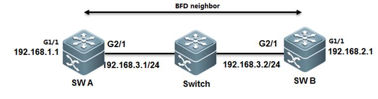
III. Configuration Tips
1. Assign IP address
2. Associate PBF with BFD
IV. ConfigurationSteps
Configuring SWA
1. Assign IP address to G2/1 on SWA andconfigure BFD
SWA#configure terminal
SWA(config)#interface GigabitEthernet2/1
SWA(config-if)#no switchport
SWA(config-if)#ip address 192.168.3.1 255.255.255.0
SWA(config-if)#bfd interval 500 min_rx 500 multiplier 3 ------>set BFD timeparameter and enable BFD on the interface. We suggest you to use 500/500/3value . BFD sends a detection packet every 500ms and is timeout when BFDdoesn't receive replies three times.
SWA(config-if)#no bfd echo ------>by default BFD echo mode is on .when a FW or devicesof other vendors connect between two BFD peers , the devices can possiblefilter BFD packets ,then BFD will fail to build connections . We suggest youto disable BFD echo
2. Assign IP address to G1/1 on SWA
SWA(config-if)#exit
SWA(config)#interface GigabitEthernet1/1
SWA(config-if)#no switchport
SWA(config)#ip address 192.168.1.1 255.255.255.0
3. Associate PBR with BFD
SWA(config)#ip access-list extended 100
SWA(config-ext-nacl)#permit ip any 192.168.2.0 0.0.0.255
SWA(config-ext-nacl)#deny ip any any
SWA(config-ext-nacl)#exit
SWA(config)#route-map Example1 permit 10
SWA(config-route-map)#match ip address 100
SWA(config-route-map)#set ip precedence priority
SWA(config-route-map)#setip next-hop verify-availability 192.168.3.2 bfd GigabitEthernet 0/1 192.168.3.2
SWA(config)#end
SWA#wr
Configuring SWB
1. Assign IP address to G2/1 on SWB andconfigure BFD
SWB#configure terminal
SWB(config)#interface GigabitEthernet 2/1
SWB(config-if)#no switchport
SWB(config-if)#ip address 192.168.3.2 255.255.255.0
SWB(config-if)#bfd interval 500 min_rx 500 multiplier 3 ------>set BFD timeparameter and enable BFD on the interface. We suggest you to use 500/500/3value . BFD sends a detection packet every 500ms and is timeout when BFDdoesn't receive replies three times.
SWB(config-if)#no bfd echo ------>by default BFD echo mode is on .when a FW or devicesof other vendors connect between two BFD peers , the devices can possiblefilter BFD packets ,then BFD will fail to build connections . We suggest youto disable BFD echo
2. Assign IP address to G1/1 on SWB
SWB(config-if)#exit
SWB(config)#interface GigabitEthernet1/1
SWB(config-if)#no switchport
SWB(config)#ip address 192.168.2.1 255.255.255.0
3. Associate PBR with BFD
SWB(config)#ip access-list extended 100
SWB(config-ext-nacl)#permit ip any 192.168.1.0 0.0.0.255
SWB(config-ext-nacl)#deny ip any any
SWB(config-ext-nacl)#exit
SWB(config)#route-map Example1 permit 10
SWB(config-route-map)#match ip address 100
SWB(config-route-map)#set ip precedence priority
SWB(config-route-map)#setip next-hop verify-availability 192.168.3.1 bfd GigabitEthernet 2/1 192.168.3.1
SWB(config)#end
SWB#
V. Verification
1. How to display BFD neighbor status
Ruijie#show bfd neighbors details
OurAddr NeighAddr LD/RD RH/RS Holdown(mult) State Int
192.168.3.1 192.168.3.2 1/2 Up 532 (3 ) Up Ge2/1
LocalDiag: 0, Demand mode: 0, Poll bit: 0
MinTxInt:200000, MinRxInt: 200000, Multiplier: 5
ReceivedMinRxInt: 50000, Received Multiplier: 3
Holdown(hits): 600(22), Hello (hits): 200(84453)
RxCount: 49824, Rx Interval (ms) min/max/avg: 208/440/332
TxCount: 84488, Tx Interval (ms) min/max/avg: 152/248/196
Registeredprotocols: PBR
Uptime:02:18:49
Lastpacket: Version: 1 - Diagnostic: 0
IHear You bit: 1 - Demand bit: 0
Pollbit: 0 - Final bit: 0
Multiplier:3 - Length: 24
MyDiscr.: 2 - Your Discr.: 1
Mintx interval: 50000 - Min rx interval: 50000
MinEcho interval: 0
2. How to display detail BFD neighborinformation
Ruijie#show bfd neighbors details
OurAddr NeighAddr LD/RD RH/RS Holdown(mult) State Int
192.168.3.2 192.168.3.1 2/1 Up 532 (5 ) Up Ge2/1
LocalDiag: 0, Demand mode: 0, Poll bit: 0
MinTxInt:50000, MinRxInt: 50000, Multiplier: 3
ReceivedMinRxInt: 500000, Received Multiplier: 5
Holdown(hits): 600(22), Hello (hits): 200(84453)
RxCount: 49824, Rx Interval (ms) min/max/avg: 209/440/332 last: 66 ms ago
TxCount: 84488, Tx Interval (ms) min/max/avg: 153/249/197 last: 190 ms ago
Registeredprotocols: PBR
Uptime:02:18:49
Lastpacket: Version: 1 - Diagnostic: 0
IHear You bit: 1 - Demand bit: 0
Pollbit: 0 - Final bit: 0
Multiplier:5 - Length: 24
MyDiscr.: 1 - Your Discr.: 2
Mintx interval: 500000 - Min rx interval: 500000
MinEcho interval: 0
Relevant info as below:
| Field | Description |
| OurAddr | IP address for the session on the local end |
| NeighAddr | IP address for the adjacent session |
| LD/RD | Session discriminator on the local and peer end |
| RH/RS | Current status of the session peer end |
| Holdown(mult) | Time of not receiving the Hello packets on the local end and the detected timeout time of the session |
| State | Current session state |
| Int | Interface number for the session |
| Session state is UP and using echo function with 50 ms interval | Whether the session is in echo mode and the interval of sending frames. This information is shown only in the echo mode |
| Local Diag | Diagnostic information of the session |
| Demand mode | Whether the demand mode is enabled or not |
| Poll bit | Whether the session configuration is modified |
| MinTxInt | Minimum sending interval of the session on the local End |
| MinRxInt | Minimum receiving interval of the session on the local end |
| Multiplier | Timeout times detected on the local end |
| Received MinRxInt | Minimum sending interval of the session on the peer end |
| Received Multiplier | Timeout times detected on the peer end |
| Holdown (hits) | Session detection time and the detected timeout times |
| Hello (hits) | Minimum interval of receiving the Hello packet after the session negotiation |
| Rx Count | Count of BFD packets received on the local end |
| Rx Interval (ms) min/max/avg | Minimum/maximum/average interval of receiving the session on the local end |
| Tx Count | Count of BFD packets sent on the local end |
| Tx Interval (ms) min/max/avg | Minimum/maximum/average interval of sending the session on the local end |
| Registered protocols | Type of protocol registered to the session |
| Uptime | Time of keeping the session UP |
| Last packet | Last BFD packet received on the local end |
2.9.7.2 DLDP
Overview
DLDP:Data Link Detection Protocol (DLDP) is a protocol designed to detectEthernet link fault quickly.
Based on the SDH platform, the MSTP supports access,processing, and transmission of multiple services, such as TDM, ATM, andEthernet, providing a multi-service node for the unified network managementsystem. Because Ethernet lacks in the link keep-alive protocol, Ethernet accessis always used at user access points. As a result, link protocol status isstill normal even if lines for Ethernet to access the MSTP network aredisconnected. In this case, route convergence slows down and the difficulty inlocating a fault is increased.
The major procedure for device link detection can bedivided into the following stages:
Initialization stage
When DLDP is enabled on the interface, DLDP is changedintoinitialization status, and then an ARP request is sent to obtain the MACaddress of the peer device. If DLDP cannot obtain the peer MAC address, DLDP isin the initialization stage unless users prohibit this function and DLDP statusis changed into deleted. After the peer MAC address is obtained, DLDP status ischanged into link succeeded.
Link succeeded status
In this state, DLDP can send a link detection requestto detect line connectivity. After DLDP responses are received, the interfaceis marked UP. If responses are not received, requests are sent until the numberof requests exceed the maximum number. In this case, the link is marked failedand DLDP status is changed into initialization. If users delete this functionduring this process, DLDPstatus is changed into deleted.
Deleted status
In deleted state, the interface status is not analyzedby the link detection function. In thiscase, the interface status is consistentwith the physical channel status.
The devices on both sides detected by DLDP can be setto work in active/passive mode. In the passive mode, DLDP detection packets arenot sent actively and only the DLDP detection packets from the peer end aredetected and replied to
for link detection. When multi-channel DLDP detectionis configured on a convergence router, the passive mode can greatly reduceprocessing load of the convergence device and traffic load of lines. In thepassive mode, the peer end must be set to active mode so that the devices onboth sides can normally work with each other.
The difference between DLDP and BFD:
1. You must apply DLDP on ethernet port , and you canapply BFD between any two hosts regardless port type.
2. DLDP utilizes ICMP ,and BFD utilizes BFD mechanism.
3. You can apply DLDP on one end beceasue DLDP is aunidirection detection , but you must apply BFD on both ends becasue BFD is abidirection detection
4. DLDP bases on port ,and when DLDP detection failed ,DLDP shuts the port down (for example , SVI , Layer 3 port) and remove all theroutes that is related to the port. BFD bases on pairs , when BFD detectionfailed , BFD controls only the specific route.
I. Requirements
The following figure provides two equal access to twodifferent service providers ,and there are two static routes . route of ISP 1is main path and route of ISP2 is a floating route, and it is the"backup" or redundant path.
The issue is when FW1 connects between R1 and SW ,evenif ISP 1 is down , SW cannot detect the issue and will still forward traffic toR1. Administrator can enable DLDP to solve this problem
II. Network Topology
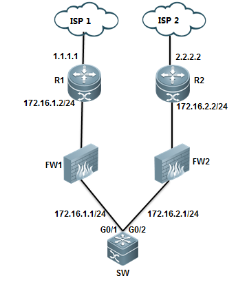
III. Configuration Tips
1. Configure two default routes on SW, oneroute points to ISP1 at 172.16.1.2, the other route is floating route andpoints to ISP2 at 172.16.2.2
2 .Configure DLDP on SW to detects ISP 1 at1.1.1.1 with next-hop 172.16.1.2
IV. ConfigurationSteps
Configuring SW
1. Assign IP address and configure basic IProuting
Ruijie#configureterminal
Ruijie(config)#interfacegigabitEthernet 0/1
Ruijie(config-if-GigabitEthernet0/1)#no switchport
Ruijie(config-if-GigabitEthernet0/1)#ip address 172.16.1.1 255.255.255.0
Ruijie(config-if-GigabitEthernet0/1)#exit
Ruijie(config)#interfaceGigabitEthernet 0/2
Ruijie(config-if-GigabitEthernet0/2)#no switchport
Ruijie(config-if-GigabitEthernet0/2)#ip address 172.16.2.1 255.255.255.0
Ruijie(config-if-GigabitEthernet0/2)#exit
Ruijie(config)#iproute 0.0.0.0 0.0.0.0 172.16.1.2 ------>configuredefault route
Ruijie(config)#iproute 0.0.0.0 0.0.0.0 172.16.2.2 20 ------> configurefloating static route with metric 20
2. Configure DLDP on SW
Ruijie(config)#interfacegigabitEthernet 0/1
Ruijie(config-if-GigabitEthernet0/1)#dldp 1.1.1.1 next-hop 172.16.1.2 ------>detect ISP 1 at 1.1.1.1 withnext-hop 172.16.1.2
By default ,DLDP sends a detection packetevery 1000 ms and sends 4 detection packet in all , if all detection packetsare failed , DLDP is timeout and can resume when receiveing 3 continuousreplies
Ruijie(config)#showdldp interface gigabitEthernet 0/1
Interface Type Ip Next-hop Interval Retry Resume State
---------------- --------------- --------------- -------- ----- ------ -----
Gi0/4 Active 1.1.1.1 172.16.1.2 100 4 3
DLDP command format :
Ruijie(config-if)# dldp ip-address [next-hop ip-address ] [ interval tick ] [ retry retry-num ] [ resume resume-num]
Use this command to enable the DLDPdetection function
next-hop ip-address:The nexthop IP address
Interval tick:The detection interval time. The valid range is 1 to3600, in ticket, 1 ticket approximately equals to 10ms . By default it is 100ticket(1 second).
retry retry-num:Theretransmission times. The valid range is 1 to 3600,4by defaultl .System change port state from up to down if no reply after sending4 icmp echo
resume resume-num:The resumetimes of the link of the peer device detected. Before changing the link statefrom DOWN to UP, the continuous DLDP detection packets shall be received. Thevalid range is 1-200. 3 by default.
3. DLDP Optimization
Modify parameters based on the followingrules :
Note:
1) DLDP allows to configure multiple ICMPdetection on the same layer 3 port. Port changes to down when all ICMPdetection fails and to recovers when one ICMP detection resumes.
2) DLDP uses the interface primary IPaddress as the communication source.
3) Pay attention to CPP and NFPP settingwhen require many ICMP detections (e.g more than 100 IP detection and 20pps foreach IP) Suggest to turn off ICMP-Guard :
Ruijie#configureterminal
Ruijie(config)#nfpp
Ruijie(config-nfpp)#noicmp-guard enable
Ruijie(config-nfpp)#end
Ruijie#wr
andtune CPP parameters :
Ruijie(config)#cpu-protecttype icmp bandwidth 4096
V. Verification
1. Display IP route table when DLDP doesn'ttime out
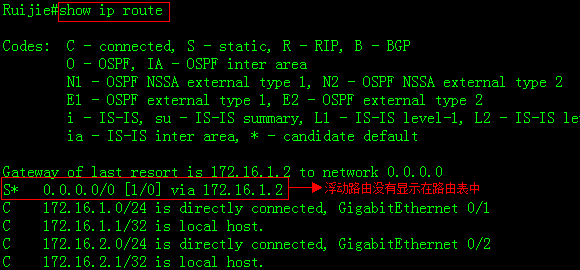
2. Display DLDP status
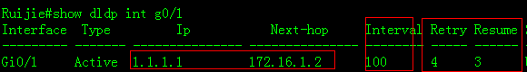
3. Show debug to describe how DLDP works
Ruijie#debug ip icmp ------>enable debug ip icmp then shutdown loopback 0
*Mar29 14:21:26: %7: ICMP: echo reply rcvd, src 1.1.1.1, dst 172.16.1.1
*Mar29 14:21:27: %7: ICMP: echo reply rcvd, src 1.1.1.1, dst 172.16.1.1
*Mar29 14:21:28: %7: ICMP: echo reply rcvd, src 1.1.1.1, dst 172.16.1.1
*Mar29 14:21:29: %7: ICMP:sending redirect host to 172.16.1.1,gw 172.16.1.2
*Mar29 14:21:29: %7: ICMP:sending ttl(time to live) exceeded to 172.16.1.1
*Mar29 14:21:29: %7: ICMP:redirect rcvd from 172.16.1.1 --for dst 1.1.1.1 use gw172.16.1.2
*Mar29 14:21:29: %7: ICMP: time exceeded rcvd from 172.16.1.1------>1sttimeout
*Mar29 14:21:30: %7: ICMP:sending redirect host to 172.16.1.1,gw 172.16.1.2
*Mar29 14:21:30: %7: ICMP:sending ttl(time to live) exceeded to 172.16.1.1
*Mar29 14:21:30: %7: ICMP:redirect rcvd from 172.16.1.1 --for dst 1.1.1.1 use gw172.16.1.2
*Mar29 14:21:30: %7: ICMP: time exceeded rcvd from 172.16.1.1------>2ndtimeout
*Mar29 14:21:31: %7: ICMP:sending redirect host to 172.16.1.1,gw 172.16.1.2
*Mar29 14:21:31: %7: ICMP:sending ttl(time to live) exceeded to 172.16.1.1
*Mar29 14:21:31: %7: ICMP:redirect rcvd from 172.16.1.1 --for dst 1.1.1.1 use gw172.16.1.2
*Mar29 14:21:31: %7: ICMP: time exceeded rcvd from 172.16.1.1------>3rdtimeout
*Mar29 14:21:32: %7: ICMP:sending redirect host to 172.16.1.1,gw 172.16.1.2
*Mar29 14:21:32: %7: ICMP:sending ttl(time to live) exceeded to 172.16.1.1
*Mar29 14:21:32: %7: ICMP:redirect rcvd from 172.16.1.1 --for dst 1.1.1.1 use gw172.16.1.2
*Mar29 14:21:32: %7: ICMP: time exceeded rcvd from 172.16.1.1------>shutdownport after 4th timeout
*Mar29 14:21:33: %DLDP-5-STATECHANGE: Interface GigabitEthernet 0/1 - Dldp 1.1.1.1state changed to down.
*Mar29 14:21:33: %7: ICMP:sending redirect host to 172.16.1.1,gw 172.16.1.2
*Mar29 14:21:33: %7: ICMP:sending ttl(time to live) exceeded to 172.16.1.1
*Mar29 14:21:33: %7: ICMP:redirect rcvd from 172.16.1.1 --for dst 1.1.1.1 use gw172.16.1.2
*Mar29 14:21:33: %7: ICMP: time exceeded rcvd from 172.16.1.1
*Mar29 14:21:34: %LINEPROTO-5-UPDOWN: Line protocol on Interface GigabitEthernet0/1, changed state to down.
4. When DLDP detection fails , DLDPshutdowns the port , then floating static route is installed in IP route table.
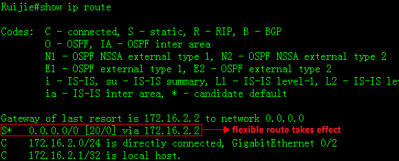
2.9.7.3 RLDP
Overview
RLDP:RapidLink Detection Protocol is one of Ruijie's proprietary link protocol designedto detect Ethernet link fault quickly.
General Ethernet link detection mechanism only makesuse of the status of the physical connections and detects the connectivity ofthe link via the auto-negotiation of the physical layer. This detection mechanismhas restrictions and sometimes cannot provide reliable link detectioninformation for the user. For example, if the optical fiber receiving line pairon the optical interface is misconnected, due to the existence of the opticalconverter, the related port of the device is"linkup" physically butactually the corresponding layer-2 link cannot work for communications.
The RLDP enables easy detection of Ethernet device linkfault, including the one-way link fault, two-way link fault and loop linkfault.
BPDU Guard: BPDU Guard put ports in err-disable status if portsreceive BPDU packets
Common layer 2 loops occurs in following scenarioes
1. Both core switches connect to a same accessswtich
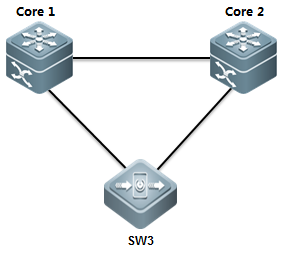
In tis scenarin, you can enable MSTP to prevent loopand ensure network redundancy.
2. Both access swithes connect double links tocore switch
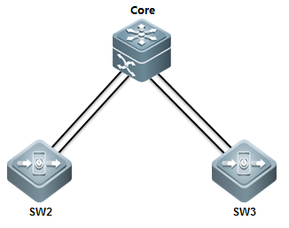
In this scenario , you can enable Aggregateport(AP) to prevent loop and ensure network redundancy
3. one cable connects to two ports on a sameswitch
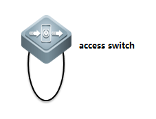
In this scenario , you can enable RLDP orBPDU Guard to prevent loop
4. Access switch connects to a hub and aloop occurs in the hub
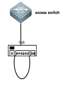
In this scenario , we suggest you to enableRLDP rather than BPDU Guard to prevent loop because BPDU Guard is astandard protocol and utilizes multicast packets at MAC 01-80-C2-00-00-00 toconmunicate.Some hubs can probably filter packets sent to this MAC ,so evenwhen a loop occurs , BPDU Guard doesn't put the port in err-disablestatus.Compare with BPDU Guard , RLDP is Ruijie private protocol that utilizesmutlicast packets at MAC 01-d0-f8-00-00-02 to communicate which doesn't befiltered.
I. Requirements
Administrator wants to enable RLDP on edgeports on access switch to prevent loop
II. Configuration Tips
1. Enable RLDP globally
2. Configure RLDP on interfaces
3. Configure error recovery interval
III. Network Topology
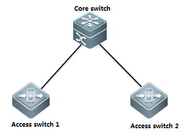
IV. ConfigurationSteps
Configuringaccess switch :
Rujijie#configureterminal
Rujijie(config)#rldpenable ------>enable RLDP globally
Rujijie(config)#interfacerange g0/1-24 ------> configure a range interfaces
Rujijie(config-if-range)#rldpport loop-detect shutdown-port ------>If RLDP detects a loop , RLDPshutdown this port
Rujijie(config-if-range)#exit
Rujijie(config)#errdisablerecovery interval 300 ------> those ports recover after 300s
Rujijie(config)#end
Rujijie#wr
Note:
1) We suggest you to enable BPDU Guard andPortfast at the same time (you must enable STP first)
Rujijie#configureterminal
Ruijie(config)#spanning-tree
Ruijie(config)#interfacerange g0/1-24
Ruijie(config-if-range)#spanning-treebpduguard enable
Ruijie(config-if-range)#spanning-treeportfast
Ruijie(config)#interfacegigabitEthernet 0/25
Ruijie(config-if-GigabitEthernet0/25)#spanning-tree bpdufilter enable
Ruijie(config-if-GigabitEthernet0/25)#exit
Rujijie(config)#errdisablerecovery interval 300
Rujijie(config)#end
Rujijie#wr
V. Verification
1. How to display RLDP status
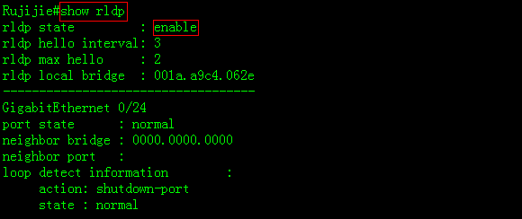
2. System returns following messages when aloop occurs between ports G0/5 and G0/7
Rujijie#
*Mar19 20:16:00: %RLDP-3-LINK_DETECT_ERROR: loop detection error detect oninterface GigabitEthernet 0/7.set this interface errordisable!
*Mar19 20:16:00: %RLDP-3-LINK_DETECT_ERROR: loop detection error detect oninterface GigabitEthernet 0/5.set this interface errordisable!
Mar19 20:16:01: %LINEPROTO-5-UPDOWN: Line protocol on Interface VLAN 1, changedstate to down.
*Mar19 20:16:02: %LINK-3-UPDOWN: Interface GigabitEthernet 0/5, changed state todown.
*Mar19 20:16:02: %LINEPROTO-5-UPDOWN: Line protocol on Interface GigabitEthernet0/5, changed state to down.
*Mar19 20:16:02: %LINK-3-UPDOWN: Interface GigabitEthernet 0/7, changed state todown.
*Mar19 20:16:02: %LINEPROTO-5-UPDOWN: Line protocol on Interface GigabitEthernet0/7, changed state to down.
3. RLDP shutdown both ports G0/5 and G0/7
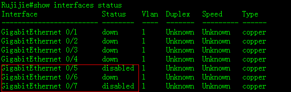
4. Both ports recover after 300s :
*Mar19 20:21:01: %PORT_SECURITY-4-ERR_RECOVER: Interface GigabitEthernet 0/5recover from an error.
*Mar19 20:21:01: %PORT_SECURITY-4-ERR_RECOVER: Interface GigabitEthernet 0/7recover from an error.
*Mar19 20:21:01: %RLDP-3-LINK_DETECT_RECOVER: rldp recover interfaceGigabitEthernet 0/7 from loop error
*Mar19 20:21:01: %RLDP-3-LINK_DETECT_RECOVER: rldp recover interfaceGigabitEthernet 0/5 from loop error
*Mar19 20:21:04: %LINEPROTO-5-UPDOWN: Line protocol on Interface VLAN 1, changedstate to up.
*Mar19 20:21:06: %LINK-3-UPDOWN: Interface GigabitEthernet 0/5, changed state toup.
*Mar19 20:21:06: %LINEPROTO-5-UPDOWN: Line protocol on Interface GigabitEthernet0/5, changed state to up.
*Mar19 20:21:06: %LINK-3-UPDOWN: Interface GigabitEthernet 0/7, changed state toup.
*Mar19 20:21:06: %LINEPROTO-5-UPDOWN: Line protocol on Interface GigabitEthernet0/7, changed state to up.
5. Execute "rldp reset" EXECcommand to rest all ports in disabled status immediately
Rujijie#rldpreset
Rujijie#
*Mar19 20:34:32: %PORT_SECURITY-4-ERR_RECOVER: Interface GigabitEthernet 0/7recover from an error.
*Mar19 20:34:32: %RLDP-3-LINK_DETECT_RECOVER: rldp recover interfaceGigabitEthernet 0/7 from loop error
*Mar19 20:34:32: %PORT_SECURITY-4-ERR_RECOVER: Interface GigabitEthernet 0/5recover from an error.
*Mar19 20:34:32: %RLDP-3-LINK_DETECT_RECOVER: rldp recover interfaceGigabitEthernet 0/5 from loop error
2.9.8 Multicast
2.9.8.1 IGMP Snooping
Overview
IGMP Snooping:Internet Group Management Protocol, abbreviated as IGMPSnooping, is an IP multicast flow mechanism running in the VLAN, and used tomanage and control the IP multicast flow forwarding in the VLAN and belongs tothe Layer2 multicast function. The IGMP Snooping function described below is inthe VLAN, and the related ports are the member ports in the VLAN.
The device running IGMP Snooping sets up the mappingfor the port and the multicast address by analyzing the received IGMP packets,and forwards the IP multicast packets based on the mapping. With IGMP Snoopingenabled, the IP multicast packets are broadcasted in the VLAN; while with IGMPSnooping enabled, the known IP multicast packets are not broadcasted in theVLAN but sent to the specified recipient.
I. Requirements
1) As the figure shown, core switch connectsto multicast source and runs multicast routing. Access switch connects to users(for example, PC1 and PC2) in Vlan 10
2) Enable multicast routing protocol inPIM-DM mode on Core switch. Enable IGMP Snooping in IVGL mode on access switch.
3) Users can only join legal multicast groupfrom 225.1.1.1 to 225.1.1.10.
4) Enable fast leave on all ports connectedto users on access switch.
5) On access switch, suppress responsepackets from IGMP member to core switch to decrease the burden of core switch.
II. Configuration Tips
1) Enable multicast routing protocol inPIM-DM mode on every corresponding Layer 3 port on Core switch . Enable IGMPSnooping in IVGL mode on access switch and specify the uplink interface as IGMPSnooping route port.
2) Configure IGMP Filter on access switch toprevent user from joining the illegal multicast group
3) Enable fast-leave on access switch
4) Enable IGMP Snooping supression on accessswitch
III. Network Topology
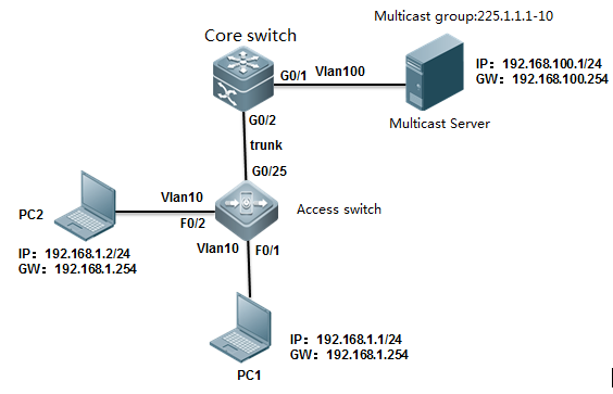
IV. ConfigurationSteps
Configuring core switch:
1) Create vlans and enable multicast routing
Ruijie#configureterminal
Ruijie(config)#vlan10
Ruijie(config-vlan)#vlan100
Ruijie(config-vlan)#exit
Ruijie(config)#ipmulticast-routing
2) Assign G0/1 connected to multicast sourceto vlan 100 and enable multicast protocol in PIM-DM mode on SVI 100
Ruijie(config)#interfacegigabitEthernet 0/1
Ruijie(config-if-GigabitEthernet0/1)#switchport access vlan 100
Ruijie(config-if-GigabitEthernet0/1)#exit
Ruijie(config)#interfacevlan 100
Ruijie(config-if-VLAN100)#ip address 192.168.100.254 255.255.255.0
Ruijie(config-if-VLAN100)#ip pim dense-mode
3) Assign IP address to VLAN 10 and enablemulticast protocol in PIM-DM mode on SVI 10
Ruijie(config)#interfacevlan 10
Ruijie(config-if-VLAN10)#ip address 192.168.10.254 255.255.255.0
Ruijie(config-if-VLAN10)#ip pim dense-mode
Ruijie(config-if-VLAN10)#exit
4) Configure G0/2 connected to access switchas trunk port
Ruijie(config)#interfacegigabitEthernet 0/2
Ruijie(config-if-GigabitEthernet0/2)#switchport mode trunk
Ruijie(config-if-GigabitEthernet0/2)#exit
5) Save configuration
Ruijie(config)#end
Ruijie#wr
Configuring access switch:
1) Create vlan , assign ports connceted tousers to vlan 10 and configure G0/25 connected to core switch as trunk port
Ruijie(config)#vlan10
Ruijie(config-vlan)#exit
Ruijie(config)#interfacegigabitEthernet 0/25
Ruijie(config-if-GigabitEthernet0/25)#switchport mode trunk
Ruijie(config-if-GigabitEthernet0/25)#exit
Ruijie(config)#interfacerange fastEthernet 0/1-2
Ruijie(config-if-range)#switchportaccess vlan 10
Ruijie(config-if-range)#exit
2) Enable IGMP Snooping in IVGL mode andspecify G0/25 as IGMP Snooping route port for vlan 10.
Ruijie(config)#ipigmp snooping ivgl
Ruijie(config)#ipigmp snooping vlan 10 mrouter interface g0/25
Ruijie(config)#end
3) Enable IGMP Filter to allow user joinlegal multicast group from 225.1.1.1 to 226.1.1.1 only
Ruijie(config)#ipigmp profile 1
Ruijie<config-profile>#permit
Ruijie<config-profile>#range225.1.1.1 225.1.1.10
Ruijie<config-profile>#exit
Ruijie(config)#interfacerange fastEthernet 0/1-2
Ruijie(config-if-range)#ipigmp snooping filter 1
Ruijie(config-if-range)#exit
4) Enable fast-leave
Ruijie(config)#ipigmp snooping fast-leave enable
5) Enable IGMP Snooping supression
Ruijie(config)#ipigmp snooping suppression enable
Ruijie(config)#end
Ruijie#wr
V. Verification
1) How to display IGMP Snooping table onaccess switch
Ruijie# show ip igmp snooping gda-table
MulticastSwitching Cache Table
D: DYNAMIC
S: STATIC
M: MROUTE
(*,229.255.255.250, 10): ------>illegal igmp snooping entry ,you can enter "ipigmp snooping filter 1" interface configuration command to filter it
VLAN(10) 2 OPORTS:
GigabitEthernet 0/25(M)
FastEthernet 0/2(D)
(*,239.255.255.250, 10): ------>illegal igmp snooping entry ,youcan enter "ip igmp snooping filter 1" interface configuration commandto filter it
VLAN(10) 2 OPORTS:
GigabitEthernet 0/25(M)
FastEthernet 0/2(D)
(*,225.1.1.1, 10): ------>legal igmp snooping entry
VLAN(10) 2 OPORTS:
GigabitEthernet 0/25(M) ------>M indicates the route port
FastEthernet 0/2(D) ------>D indicates the user port
2) How to display IGMP Snooping statistics
Ruijie#showip igmp snooping statistics
Currentnumber of Gda-table entries: 1 ------>number of igmpsnooping entries
ConfiguredStatistics database limit: 1024 ------>max number ofentries
Currentnumber of IGMP Query packet received : 0
Currentnumber of IGMPv1/v2 Report packet received: 0
Currentnumber of IGMPv3 Report packet received: 0
Currentnumber of Leave packet received: 0
Currentnumber of PIM packet received: 0
Currentnumber of DVMRP packet received: 0
GROUP Interface Last report time Last leave time Lastreporter Report pkts Leave pkts
--------------- -------------- ---------------- ------------------------------- ------- -------
225.1.1.1 VL10:Fa0/2 ---- ---- ---- 0 0
3) How to display igmp snooping route port
Ruijie#showip igmp snooping mrouter
MulticastSwitching Mroute Port
D: DYNAMIC
S: STATIC
(*,*, 10):
VLAN(10) 1 MROUTES:
GigabitEthernet 0/25(S)
2.9.8.2 Multicast optimization
Optimization on access switch:
Enable IGMP Filter on access switch tofilter illegal multicast group
Optimization on core switch :
1) Enable IGMP Snooping in IVGL mode on coreswitch which is user gateway
2) Apply ACL on the trunk port connected toaccess switch in input direction to prevent illgal multicast source
3) Apply IGMP filter on SVI port which isuser gateway
4) Prune trunk port
5) Filter illegal register packets on RP
6) Filter illegal BSR(Dynamic RP)
7) Filter C-RP on BSR
1. Optimization on access switch:
1)This example enables IGMP Filter on portsconnected to users to allow users join legal multicast group from 225.1.1.1 to225.1.1.10(highly recommend)
S86E(config)#ipigmp profile 1
S86E(config-profile)#permit
S86E(config-profile)#range225.1.1.1 225.1.1.10 ------>specify legal mulitcast IP range
S86E(config-profile)#exit
S86E(config)#interfacerange fastEthernet 0/1-2
S86E(config-if-range)#ipigmp snooping filter 1 ------>apply filter on the interface
S86E(config-if-range)#exit
This example displays the IGMP Snoopingtable before applying IGMP Snooping filter ,and illegal entries exists
Ruijie# show ip igmp snooping gda-table
MulticastSwitching Cache Table
D: DYNAMIC
S: STATIC
M: MROUTE
(*,229.255.255.250, 10): ------>illegal ip igmp snooping entry
VLAN(10) 2 OPORTS:
GigabitEthernet 0/25(M)
FastEthernet 0/2(D)
(*,239.255.255.250, 10): ------>illegal ip igmp snooping entry
VLAN(10) 2 OPORTS:
GigabitEthernet 0/25(M)
FastEthernet 0/2(D)
(*,225.1.1.1, 10): ------>legal ip igmp snooping entry
VLAN(10) 2 OPORTS:
GigabitEthernet 0/25(M)
FastEthernet 0/2(D)
When you finish applying IGMP Snoopingfilter , enter "clear ip igmp snooping gda-table" EXEC command toclear IGMP Snooping table , then display IGMP Snooping table again.
Ruijie#showip igmp snooping gda-table
MulticastSwitching Cache Table
D: DYNAMIC
S: STATIC
M: MROUTE
(*,225.1.1.1, 10): ------>only legal ip igmp snooping entryexists
VLAN(10) 2 OPORTS:
GigabitEthernet 0/25(M)
FastEthernet 0/2(D)
2. Optimization on core switch
1) Enable IGMP Snooping in IVGL mode on coreswitch which is user gateway(Regardlessof multicast routing protocol in PIM-DM or PIM-SM , highly recommend)
Why we should enable IGMP Snooping on a Layer3 switch that have multicast routing protocol enabled and the switch is alsothe user gateway.
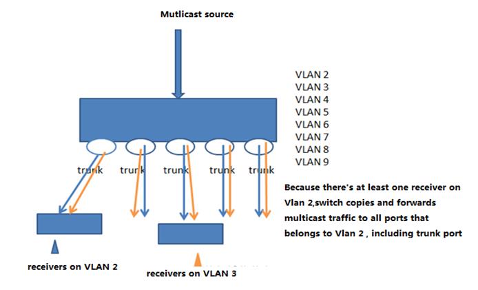
As above figure shown , switch copies andforward multicast traffic to a port even if there's no receiver on that port.
This example shows how to configure IGMPSnooping in IVGL mode to optimize switch performance.
S5750E-1(config)#ip igmp snooping ivgl
2) Apply ACL on the trunk port connected toaccess switch in input direction to prevent illgal multicast source(If you've enable IGMP Snoopingfilter on access switch , this step is a option.)
This example shows a illegal multicastgroups can take up plenty room in IGMP table
Ruijie#showip igmp groups
IGMPConnected Group Membership
GroupAddress Interface Uptime Expires Last Reporter
225.1.1.1 VLAN 100 00:00:30 00:03:50 192.168.100.1
225.1.1.1 VLAN 10 00:06:36 00:02:20 0.0.0.0
229.255.255.250 VLAN 10 00:08:46 00:02:24 0.0.0.0
239.255.255.250 VLAN 10 00:08:45 00:02:21 0.0.0.0
As figure shown, this example configures ACL on the trunk port or SVI in input direction to filter illegal multicastgroups
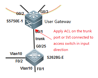
S86E(config)#ipaccess-list extended deny_mc_source
S86E(config-ext-nacl)#10permit igmp any 225.1.1.0 0.0.0.255 ------>permit legaligmp control packets
S86E(config-ext-nacl)#20deny igmp any any ------>deny any otherillegal control packets
S86E(config-ext-nacl)#30permit ip any 225.1.1.0 0.0.0.255 ------>legal multicastdata packets
S86E(config-ext-nacl)#40permit ip any 224.0.0.0 0.0.0.255 ------>IGMP packets ,need to guarantee
S86E(config-ext-nacl)#50deny ip any 224.0.0.0 15.255.255.255 ------>deny any other multicastdata packets
S86E(config-ext-nacl)#60permit ip any any
3) Apply ACL on the SVI connected to accessswitch in input direction to prevent illgal multicast source(If you've enable IGMP Snooping filter onaccess switch , this step is a option . You can choose method 2 or method 3,and we suggest you to use method 3)
This example shows a illegal multicastgroups can take up plenty room in IGMP table
Ruijie#showip igmp groups
IGMPConnected Group Membership
GroupAddress Interface Uptime Expires Last Reporter
225.1.1.1 VLAN 100 00:00:30 00:03:50 192.168.100.1
225.1.1.1 VLAN 10 00:06:36 00:02:20 0.0.0.0
229.255.255.250 VLAN 10 00:08:46 00:02:24 0.0.0.0
239.255.255.250 VLAN 10 00:08:45 00:02:21 0.0.0.0
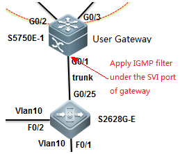
S86E(config)#ipaccess-list standard 10
S86E(config-std-nacl)#10permit 225.1.1.0 0.0.0.255 ------>legal IGMP multicast source
S86E(config-std-nacl)#20deny any
S86E(config-std-nacl)#exit
Apply ACL on SVI
S86E(config)#interfaceVLAN 10
S86E(config-VLAN10)#ip igmp access-group 10
S86E(config-VLAN10)#exit
4) Prune trunk port (highlyrecommend)
S86E(config)#interfaceVLAN 10 S86E(config)#interface gigabitEthernet 0/1
S86E(config-if-GigabitEthernet0/1)#switchport trunk allowed vlan remove 1-9,11-4094
S86E(config-if-GigabitEthernet0/1)#exit
5) Filter illegal register packets on RP(for PIM-SM , not for PIM-DM)
Ruijie(config)#ip access-list extended acl_3500
Ruijie(config-ext-nacl)#permit ip 219.229.134.0 0.0.0.255 239.202.0.0 0.0.255.255
Ruijie(config-ext-nacl)#exit
Ruijie(config)#ippim accept-register list acl_3500
6) Filter illegal BSR(Dynamic RP)(for PIM-SM , not for PIM-DM)
Ruijie(config)#ipaccess-list standard bsr_accept
Ruijie(config-std-nacl)# 10 permit host 10.10.10.1
Ruijie(config-std-nacl)# 20 permit host 10.10.10.2
Ruijie(config-std-nacl)#exit
Ruijie(config) #ip pim accept-bsr listbsr_accept
7) Filter C-RP on BSR(for PIM-SM , not for PIM-DM)
ippim accept-crp list crp_list
2.9.8.3 PIM-DM
Scenario
TheProtocol Independent Multicast-Dense Mode (PIM-DM) is the PIM in dense mode,suitable for a small-scale network with dense multicast group members. Itsworking principle is as follows:
1. The PIM-DM assumes thateach subnet of the network has at least one multicast group member and therebythe multicast data are dispersed to all nodes on the network. The PIM-DM prunesbranches to which multicast data are to forwarded and retains only branches ofmulticast data receivers. The dispersing-pruning process occurs periodically.The pruned branches can be periodically restored to the forwarding status.
2. When a multicast groupmember appears on the node of the pruned branch, the node sends a graft packetto its downstream device to turn its pruned state into a forwarding state. Inthis way, the node recovers its multicast data forwarding capability.
Configuration Example
I. NetworkingRequirements
1. The N18000-1,N18000-2, and N18000-3 are three core devices on the network. They areinterconnected to each other through L3 ports and run the OSPF on the process110. They belong to area 0.
2. The gateway of userPCs is on the N18000-1 and the multicast server is connected to the N18000-2directly. They are redistributed to the OSPF process.
3. On the N18000-1,N18000-2, and N18000-3, the L3 multicast routing protocol PIM-DM is enabled.
4. On the SS2628G-Eswitch, the L2 multicast routing protocol IVGL is enabled.
5. The PCs connected tothe S26E can access the video on the multicast server on demand.
6. Network optimizationis carried out on the multicast network to reduce traffic congestion andmulticast spoofing.
II. ConfigurationTips
1. On the three coreswitch, configure the IP addresses and enable the OSPF routing protocol. Ensurethat the server and the switch can ping through to each other.
2. On the three switches,enable the multicast routing function PIM-DM.
3. On the access server,set the IGMP Snooping mode to IVGL.
II. Network Topology
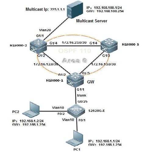
IV. Configuration Steps
Step 1. Configure thebasic IP addresses, routing, and the multicast function.
On the core servers,perform the following steps:
1. On the N18000-1,
Create VLAN 10, set theSVI address of the user gateway, configure the Trunk port that connects the accessswitch, and configure the IP addresses for the L3 interconnection with othercore servers.
2. On the N18000-2,
Create VLAN 10, set theSVI address of the multicast server gateway, configure the interface thatconnects the multicast server to Access VLAN 20, and configure the IP addressesfor the L3 interconnection with other core servers.
Note:
3. On the N18000-3,
Configure the IPaddresses for the L3 interconnection with other core servers.
On the access switch,perform the following steps:
1) Create the VLAN andpartition the VLAN. Set the port that connects users to an Access port and theuplink port to a Trunk port.
2) Set the IGMP Snoopingmode to IVGL and set the g0/25 port as the route connection port of VLAN 10.
V. Verification
1. On the switch, checkthe IGMP groups.
2. Check the PIM-DMinformation of the port.
3. Check the next hopinformation of the PIM-DM.
2.9.8.4 PIM-SM
Scenario
Protocol Independent Multicast - Sparse Mode(PIM-SM) transmits multicast data in pull mode, suitable for a large- andmedium-scale network with scattered multicast group members. Its workingprinciple is as follows:
1. The PIM-SM assumes all hosts do notrequire multicast data. Multicast data are sent only if they are explicitlyrequested. The PIM-SM develops and maintains a rendezvous point tree (RPT) asits core task. The RPT chooses a router in the PIM domain as the publicrendezvous point (RP). The multicast data are transmitted to receivers throughRPs along the RPT.
2. The router that connects receivers sendsjoin packets to the RP of the multicast group. The packet is delivered to theRP hop by hop and its path forms a branch of the RPT.
3. When the multicast source sends multicastdata to a multicast group, the designated router (DR) on the multicast sourceside registers to the RP and sends the register packet to the RP in unicastmode. The arrival of the packet on the RP triggers the establishment of theshortest path tree (SPT). Then the multicast source forwards the multicast datato the RP on the SPT. After reaching the RP, the multicast data are replicatedand forwarded to the receivers along the RPT.
Configuration Example
I. NetworkingRequirements
1. The N18000-1,N18000-2, and N18000-3 are three core devices on the network. They areinterconnected to each other through L3 ports and run the OSPF and the process110. They belong to area 0.
2. The gateway of userPCs is on the N18000-1 and the multicast server is connected to the N18000-2directly. They are redistributed to the OSPF process.
3. On the N18000-1,N18000-2, and N18000-3, the L3 multicast routing protocol PIM-SM is enabled.The static RP is used. The N18000-2 is configured as an RP.
4. On the SS2628G-Eswitch, the L2 multicast routing protocol IVGL is enabled.
5. The PCs connected tothe S26E can play the video on the multicast server on demand.
6. Network optimizationis carried out on the multicast network to reduce traffic congestion andmulticast spoofing.
II. ConfigurationTips
1. On the three coreswitch, configure the IP addresses and enable the OSPF routing protocol. Ensurethat the server and the switch can ping through to each other.
2. On the three switches,enable the multicast routing function PIM-SM.
3. On the access server,configure the IGMP Snooping function to IVGL mode.
II. Network Topology
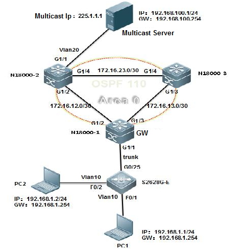
IV. ConfigurationSteps
Step 1. Configure thebasic IP addresses, routing, and the multicast function.
On the core servers,perform the following steps:
1. On the N18000-1,
Create VLAN 10, set theSVI address of the user gateway, configure the Trunk port that connects theaccess switch, and configure the IP addresses for the L3 interconnection withother core servers.
2. On the N18000-2,
Create VLAN 10, set theSVI address of the multicast server gateway, configure the interface thatconnects the multicast server to Access VLAN 20, and configure the IP addressesfor the L3 interconnection with other core servers.
3. On the N18000-3,
1) Configure the IPaddresses for the L3 interconnection with other core servers.
2) Configure the OSPFrouting on the N18000-3.
On the access switch,perform the following steps:
1) Create the VLAN andpartition the VLAN. Set the port that connects users to an Access port and theuplink port to a Trunk port.
2) Set the IGMP Snoopingmode to IVGL and set the g0/25 port as the route connection port of VLAN 10.
V. Verification
1. On the switch, checkthe IGMP groups.
2. Check all the RPs andthe groups they serve on the switch.
3. Check the BSR information.
4. Check the PIM-SMinterface information.
5. Check the PIM-SMrouting information.
2.9.9 HPOE Function
Product Introduction
POE is short for Power on Ethernet.Currently, the universal standards include IEEE 802.3af (POE) and IEEE 802.3at(POE+). The former provides 15.4W port power output and the latter provides 30Wport power output. POE involves Power Sourcing Equipment (PSE) and PoweredDevice (PD). Generally, a PSE is a switch and a PD is a terminal. Thetechnology uses two pairs of cable in one Ethernet cable to supply power.Currently, the two pairs of cable can provide a maximum power output of 30W.
Based on the current situations, this HPOEsolution enables you to supply power to a greater number of terminals throughPOE, which facilitates deployment, simplifies engineering, and reduces costs.Currently, the solution mainly is applied to weak-current intelligent systems(video surveillance systems) where POE is more widely used. It will be appliedto more fields in the future.
Figure 1 HPOE solution
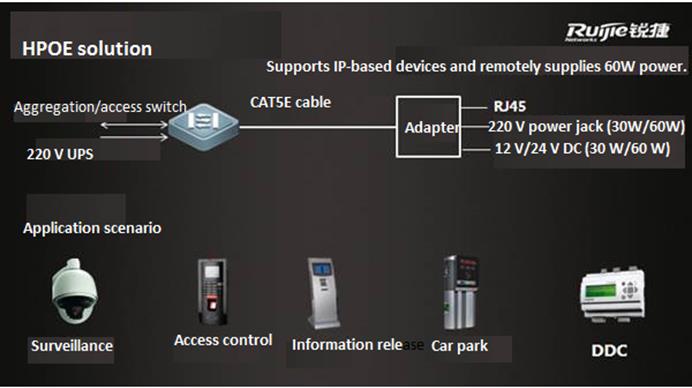
As shown in the preceding figure, the HPOEsolution leverages the HPOE core technology to supply power through Ethernetcables to IP-based devices (power < 90W) in the weak-current system. Twoproducts support HPOE, including an HPOE switch. It is connected using thecommon POE connection method to a PBOX, which then provides a power output andone Ethernet connection to the camera. In this way, highly power-demandingterminals are powered through POE.
Typical Deployment Scenario
2.1. Network Topology
A single HPOE switch or VSU is allowed. Eachdevice has four front electrical ports that support HPOE/POE/POE+ power output,and the other electrical ports support POE/POE+ power output. HPOE ports can beconnected in the following ways:
(1) HPOE port of the switch -> PBOX ->PD (device that does not support POE)
(2) HPOE port of the switch -> PD (devicethat supports POE)
2.2 Typical Networking Model
Scenario 1: Four HPOE ports work under fullload to supply power to highly power-demanding devices.
Figure 2 Networking model for scenario 1

Scenario description: In this scenario, theHPOE switch supplies power to four highly power-demanding devices at the sametime. The remaining power can be supplied using the non-HPOE ports to PDs.
Configuration requirement: All the camerascan be pinged by the switch and the POE functions of the connected ports areenabled.
Acceptance:
On the switch, use Show POE InterfacesStatus / Show POE Power Supply to view power supply information.
(2) Use a web browser to access the addressesof the cameras, enter your user names and passwords, install plug-ins, andverify that video surveillance is normal.
Scenario 2: Power is supplied through HPOE,POE, and POE+ at the same time.
Figure 3 Networking model for scenario 2
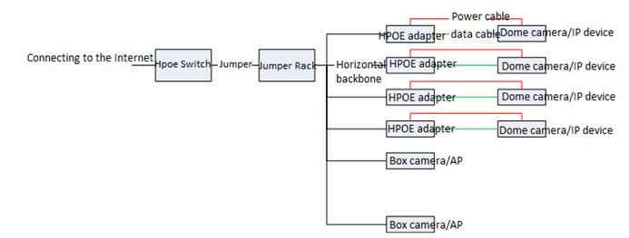
Scenario description: In this scenario, theHPOE switch supplies power to several highly power-demanding devices and lesspower-demanding devices at the same time through HPOE, POE, and POE+.
Configuration requirement: All the camerascan be pinged by the switch and the POE functions of the connected ports areenabled.
Acceptance: same as those for scenario 1
Highlight Functions
3.1 Highlight Service Functions
Function: Switch port trunk allowed VLAN onlyx-x
Original problem: By default, a port of ourswitch allows transmission of data for all VLANs after being configured as atrunk port. Therefore, frontline engineers have to configure a command toremove all VLANs before project implementation. This increases the workload andmay easily cause the loop problem.
Implementation: This function allowstransmission of data for only specified VLANs. Therefore, VLAN removal is notrequired before project implementation.
Effect:
3.2 Highlight Management Function
Function: show this
Original problem: A live network has manyconfigurations. Frontline engineers have to use show run or show runincluded/begin to view the configurations of ports or in the OSPF view.This is inconvenient.
Implementation: This function allowsengineers in a view to query the configuration commands for the view directly.
Effect:
Function: A version upgrade file name is notlimited and show upgrade history can be used to view the upgradehistory.
Original problem: The 10.X version upgradefile must be renamedrgos.bin and the version upgrade history isinaccessible.
Implementation: An version upgrade file canhave any name. This facilitates frontline planning. A command is provided forviewing the upgrade history.
Effect:
Function: debug syslog limit command
Original problem: After the debug function ofa device is enabled, debug log generation may affect the device. In some cases,it results in a device fault.
Implementation: Before the debug function isenabled, the command debug syslog limit time seconds numbers numberscan be run to limit the printing time and content of debug logs.
Function: one-key fault informationcollection
Original problem: To locate a problem thatoccurs in a product developed a long time ago, engineers must collectinformation two to three times and on-site engineers have to repeatedly triggerthe problem. This is not allowed on a live network.
Implementation: The version 11.x supportsone-key fault information collection. A single command is used to collect allrelated device operation information, including feature-related table entriesand underlying component information. The following shows how it isimplemented.
In the debug support view:
The tech-support package saves all operationinformation from the engine and line card to a file. By default, the file isstored in a USB flash drive. If no USB flash drive is available, the file isstored in the flash or tmp directory. (Recommended)
The tech-support console prints engineoperation-related information on the console.
Best Practice Solution Guide
4.1Preparation
4.1.1 Preparation before Installation
Preparation before installation
To ensure the installation successfully, make sure theinstallation site meets the requirements including ventilation, temperature,humidity, sanitary, power, fiber, cable .etc
For Detail information ,see 《hardware installation and reference guide》 of corresponding products , such as 《RG-S8600E Series Switch Hardware Installation andReference Guide,V1.10》
On the other hand, double confirm following importantinfomation ahead of schedule:
1. The network topology, configuration, IP routinginformation, user scale, traffic information and running status of currentproduction network.
2. Equipment list and pre-sale solution.
3. Customer's requirements and corresponding features
4. The campatibility with current devices, like STP, APwith switches of other vendors
5. Current link and interface status including opticalconnector, fiber etc.
6. Design the Network and acquire customer's agreement
7. Customer's network verification requirements
8. Customer's cut over plan requirements
9. Customer's acceptance inspectionrequirements
4.1.2 Check Switch Software/Hardware
Check software
This figure shows how to display soft and hardwareversion
Ruijie#show version
Software selection rules::
1. We suggest you to update the new switchto the latest firmware
2. We suggest you to update the existingswitch to the latest firmware also if they're running steady
3. For detail technical specification , seecorresponding product configuration guide ,or visit our service portal http://case.ruijienetworks.com/
Note:
Confirm whether the project is a"expansion network" or "new network"
1) If the project is a expansion network,focus on the compatibility as following :
Expansion module/line card
For detail infomation , see "HardwareSupported" in corresponding product 《releasenotes》
Expansion switch
Focus on the campatibility of differentprotols (especially MSTP) between Ruijie and other vendor.Do a full validationbefore implementation
2) If the project is a new network
Determine whether the current/latestfirmware supports customer's requirement , see configuration guide ofcorresponding product
3)Read 《release notes》and double confirm the matters need attention
Check hardware:
Take S8600E series switches as example (see 《RG-S8600E Series Switch Hardware Installation andReference Guide》)
1. M8600E-CM:
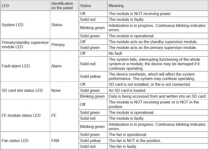
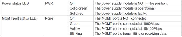
2. M8600E-24GT20SFP4XS-ED LED
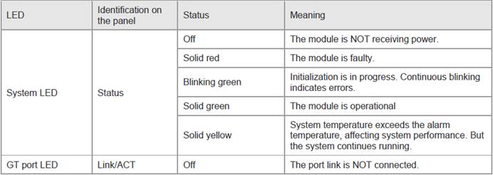
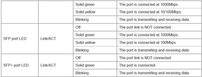
3. M8600E-48GT-ED LED
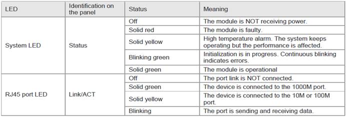
4. M8600E-48GT-EF LED
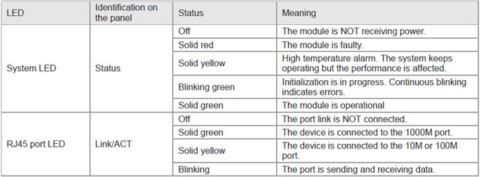
4.2 Best Practic Scenario
4.2.1 Education
Dual core using VSU
I. Requirement
1. Core swtich:Configure two S8600E chassis swithes as VSU , and connect VSU to WAN zone withdouble uplinks
2. Server farm:Connectsome Servers and storage to data center switch S6220 and S6220 is also gatewayfor servers and storage .You can also connect other servers that have equipedwith double NICs to VSU with double links
3. Aggregation switch:For Layer 3 Aggregation switches , they are usergateway and run OSPF .Connect a aggregation switch to two VSU membersindependently . For Layer 2 aggregation switch , connect them to two VSUmembers independently ,and VSU is the user gateway.
II. Network Topology
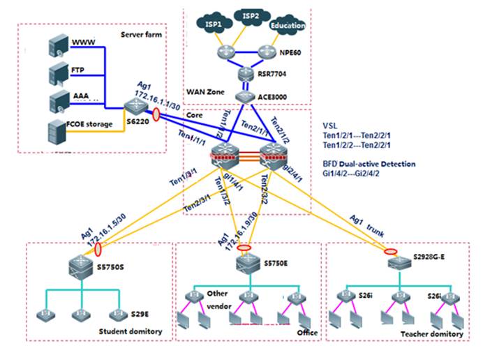
III. Common requirements and features
Select features below base on requirements:
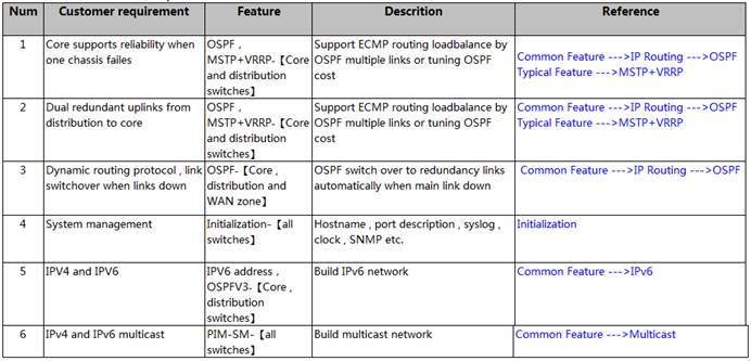
IV. Optional optimization
Select optional optimization below base onrequirements:
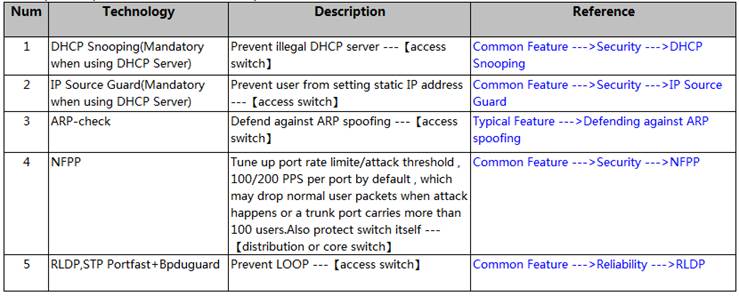
V. Verification
1. For single feature verification, seeverification method in each corresponding chapter
2. For total network running status, seeAppendix
4.3 Appendix:Common Verification Command
4.3.1 Showversion
The example shows the firmware version on a box switch:
Configuration
Ruijie#show version
For chassis switch, you must double confirm each linecard has been correctly installed
Configuration
Ruijie#show version slot
Examples
DevSlot Configured Module Online Module User Status Software Status --- ---- ----------------- ----- --------------
11 none none
12 M8606-24SFP/12GT M8606-24SFP/12GT installed none
13 M8606-2XFP M8606-2XFP uninstalled cannot startup
14 M8606-24GT/12SFP M8606-24GT/12SFP installed ok
1M1 M8606-CM M8606-CM master
1 M2
Dev:Device ID, equal to 1 bydefault, and maybe 2 or more if it is a VSU.
Slot:Slot ID slots number ofdifferent model vary, but all model has 2 engine slots --M1 and M2 and can plugin either M1 or M2 if there's only one engine.
Port:Port number of the linecard. Combo port caculates as one port only.
Configured Module :Installedmodule, and must be the same to Online Module
Online Module:Whether themodule powers on and recognized
User Status:Line cardstatus, installed or uninstalled
Software Status: "OK"indicates working properly, Master indicates primary engine, backup indicatesbackup engine.
4.3.2 Show run
This example shows how to display switch configuration
Configuration
Ruijie#show run
Examples
Ruijie#show run
Buildingconfiguration...
Currentconfiguration : 1366 bytes
version11.0(1B2)
!
cwmp
!
install3 M8600E-24XS4QXS-DB
!
sysmac1414.4b34.5624
!
nfpp
4.3.3 Show CPU
View cpu utilization every 5s, 1m or 5m by command "show cpu"
Configuration
Ruijie#show cpu
Examples
Ruijie#show cpu
===============================================
CPUUsing Rate Information
CPUutilization in five seconds: 4.80%
CPUutilization in one minute: 4.10%
CPUutilization in five minutes: 4.00%
NO 5Sec 1Min 5Min Process
1 0.00% 0.00% 0.00% init
2 0.00% 0.00% 0.00% kthreadd
3 0.00% 0.00% 0.00% ksoftirqd/0
4 0.00% 0.00% 0.00% events/0
--More--
Usually, "CPU utilization infive minutes" shall be kept below 30% ; Pay attention if it exceeds 60%.
4.3.4 Show memory
This example shows current memory status
Configuration
Ruijie#show memory
Usually, "Used Rate"shall be kept below 75%; Pay attention if it exceeds 80%.
4.3.5 Show power
This example shows the power status on achassis switch
Configuration
Ruijie#show power
Examples
Ruijie#show power
Chassis-type: RG_S8605E
Power-redun: no
Energy-saving: off
power-id power-type supply(W) status vol-in/out(V) cur-out(mA) supply-out(W)
-------- ------------ --------- ------ ------------- ----------- -------------
1 PA600I 600 ok 231 /12 3500 42
2 PA600I 600 ok 232 /12 1000 12
3 PA1600I_P 1600 ok N/A /55 0 0
4.3.6 Show fan
This example shows the fan status on achassis switch
Configuration
Ruijie#show fan
Examples
Ruijie#show fan
Chassis-type: RG_S8605E
Fan-id: 1
Fan-type: M05_FAN
Serial Number: 1234567890123
Energy-saving: off
fan-id status mode speed-level
------ ------ -------- -----------
1 ok normal N/A
4.3.7 Show temperature
This example shows the temperature status ona chassis switch
Configuration
Ruijie#show temperature
Examples
Ruijie#showtemperature
Chassis-type: RG_S8605E
slot card_type warning(C) shutdown(C) current(C)
------------------------- ------------ --------------- ------------------------------
1 N/A N/A N/A N/A
4.3.8 Show clock
Configuration
Ruijie#show clock
Examples
Ruijie#showclock
18:01:03beijing Tue, Dec 3, 2013
4.3.9 Show log
This exampleshows logs in buffer
Configuration
Ruijie#show log
Examples
Ruijie#showlog
Syslog logging: enabled
Console logging: level debugging, 15495 messages logged
Monitor logging: level debugging, 0 messages logged
Buffer logging: level debugging, 15496 messages logged
Standard format: false
Timestamp debug messages: datetime
Timestamp log messages: datetime
Sequence-number log messages: enable
Sysname log messages: enable
Count log messages: enable
Trap logging: level informational, 15242 message lines logged,0 fail
logging to 202.101.11.22
logging to 192.168.200.112
LogBuffer (Total 131072 Bytes): have written 1336,
015487:*Sep 19 02:46:13: Ruijie %LINK-3-UPDOWN: Interface FastEthernet 0/24,
This example shows how to read logs in flash
Configuration
Ruijie#more flash:syslog.txt
Examples
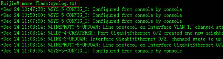
4.3.10 Verifyflash
This example shows how to display file listin flash
Configuration
Ruijie#dir
Examples
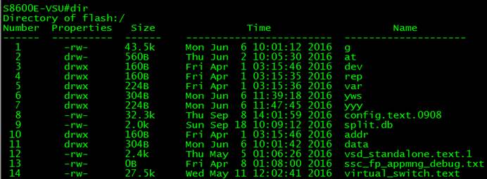
4.3.11 Verifylocal MAC address
You can enter "show arp" EXECcommand to display Layer 3 MAC address.
This example shows the Layer 3 MAC addresson S8600 switch. "--"indicates that this arp entry is a local one.
Configuration
Ruijie#show arp
Examples
Ruijie#showarp
TotalNumbers of Arp: 7
ProtocolAddress Age(min) Hardware Type Interface
Internet192.168.195.68 0 0013.20a5.7a5f arpa VLAN 1
Internet192.168.195.67 0 001a.a0b5.378d arpa VLAN 1
Internet192.168.195.65 0 0018.8b7b.713e arpa VLAN 1
4.3.12 VerifyMAC table
This example displays mac address table
Configuration
Ruijie#show mac-address-table
Examples
Ruijie#showmac-address-table
Vlan MAC Address Type Interface
---------- -------------------- -------- -------------------
1 1414.4b19.ecc0 DYNAMIC GigabitEthernet0/2
This example displays mac address statistics
Ruijie#showmac-address-table count
DynamicAddress Count : 51
StaticAddress Count : 0
FilterAddress Count : 0
TotalMac Addresses : 51
4.3.13 VerifyARP table
This example displays arp table
Configuration
Ruijie#show arp
Examples
Ruijie#showarp
TotalNumbers of Arp: 7
ProtocolAddress Age(min) Hardware Type Interface
Internet192.168.195.68 0 0013.20a5.7a5f arpa VLAN 1
Internet192.168.195.67 0 001a.a0b5.378d arpa VLAN 1
This example displays detail arp informationincluding port, vlan etc
Configuration
Ruijie#show arp detail
Examples
Ruijie#showarp detail
IPAddress MAC Address Type Age(min) Interface Port
20.1.1.1000f.e200.0001 Static -- -- --
20.1.1.1000f.e200.0001 Static -- Vl3 --
20.1.1.1000f.e200.0001 Static -- Vl3 Gi2/0/1
This example displays arp statistics
Configuration
Ruijie#show arp count
Examples
Ruijie#showarp count
TheArp Entry counter:0
TheUnresolve Arp Entry:0
4.3.14 Verifyroute table
This example displays IP route table
Configuration
Ruijie#show ip route
Examples
Ruijie#show ip route
Codes: C - Connected, L - Local, S - Static
R - RIP, O - OSPF, B - BGP, I - IS-IS, V - Overflow route
N1 - OSPF NSSA external type 1, N2 - OSPF NSSA external type 2
E1 - OSPF external type 1, E2 - OSPF external type 2
This example displays IP route statistics
Configuration
Ruijie#show ip route count
Examples
Ruijie#show ip route count
---------route info ----------
thenum of active route: 5
4.3.15 Verifyinterface IP address
This example displays IP address on Layer 3port or SVI
Configuration
Ruijie#show ip interface brief
Examples
Ruijie#show ip interface brief
InterfaceIP-Address(Pri) IP-Address(Sec) Status Protocol GigabitEthernet 0/10 2.2.2.2/243.3.3.3/24 down down GigabitEthernet 0/11 no address no address down down
VLAN1 1.1.1.1/24 no address down down
4.3.16 Verifyinterface status and description
This example displays port status of allports including link status, vlan, duplex, speed, medium type
Configuration
Ruijie#show interface status
Examples
Ruijie#Ruijie#show interfaces GigabitEthernet 0/1 status
Interface Status Vlan Duplex Speed Type
-------------------- ---------- ------ ------ ------ ------GigabitEthernet 0/1 up 1 Full 1000M copper
This example displays interface description
Configuration
Ruijie#show interface description
This example displays port status of port G0/1
Ruijie#showinterfaces gigabitEthernet 0/1
Index(dec):1(hex):1
GigabitEthernet0/1 is DOWN , line protocol is DOWN
Hardwareis marvell GigabitEthernet
Description:TO-ZGE-S8610-2_GE2/1
Interfaceaddress is: no ip address
MTU 1500 bytes, BW 1000000 Kbit
Encapsulation protocol is Bridge, loopback not set
Keepalive interval is 10 sec , set
Carrier delay is 2 sec
RXload is 1 ,Txload is 1
Queueing strategy: WFQ
Switchport attributes:
interface's description:"TO-ZGE-S8610-2_GE2/1"
medium-type is copper
lastchange time:0 Day: 0 Hour:45 Minute:26 Second
Priority is 0
admin duplex mode is AUTO, oper duplex is Unknown
admin speed is AUTO, oper speed is Unknown
flow control admin status is OFF,flow control oper status is Unknown
broadcast Storm Control is ON,multicast Storm Control is OFF,unicast StormControl is ON
5 minutes input rate 0 bits/sec, 0 packets/sec
5 minutes output rate 0 bits/sec, 0 packets/sec
37167599 packets input, 2566418459 bytes, 45 no buffer, 45 dropped ------>inputdirection dropping
Received 58764 broadcasts, 0 runts, 0 giants
0 input errors, 0 CRC, 0 frame, 0 overrun, 0 abort
37210638 packets output, 2565322398 bytes, 0 underruns , 0 dropped ------>outputdirection dropping
0 output errors, 0 collisions, 0 interface resets
4.3.17 Verifyinterface packets statistics
This example displays traffic counters onport F0/1
Configuration
Ruijie#show interface counters
Examples
Ruijie#showint fastEthernet 0/1 counters
Interface: Fa0/1
5minute input rate : 0 bits/sec, 0 packets/sec
5minute output rate : 0 bits/sec, 0 packets/sec
InOctets : 68023600
InUcastPkts : 92842
InMulticastPkts : 36700
InBroadcastPkts : 75636
OutOctets : 3630373
OutUcastPkts : 32053
OutMulticastPkts : 1059
OutBroadcastPkts : 13231
[1]Undersize packets : 0
[2]Oversize packets : 0
[3]collisions : 0
[4]Fragments : 0
[5]Jabbers : 0
[6]CRC alignment errors : 0
[7]AlignmentErrors : 0
[8]FCSErrors : 0
[9]dropped packet events (due to lack of resources): 0
[10]packets received of length (in octets):
64:119136, 65-127: 75769, 128-255: 12663,
256-511: 3149, 512-1023: 1955, 1024-1518: 38849
[1] A packet whichis shorter than Ethernet's minimum packet size of 64 bytes, but has correctchecksum.
[2] A packet whichis longer than Ethernet's maximum packet size of 1518 bytes, but has correctchecksum.
[3] Collisions:multiple sites try to send traffic at the same time, leading to a collision, usuallyit's the duplex problem
[4] A packet whichis shorter than Ethernet's minimum packet size of 64 bytes, but has wrongchecksum.
[5] A packet whichis shorter than Ethernet's minimum packet size of 1518 bytes, but has wrong checksum.
[6] CRC alignmenterrors: The same to FCS, CRC is the local checksum .Peer recalculates andcompares with FCS after receiving the packet
[7] Alignmenterror:Alignment errors are caused by misalignedreads and writes
[8] Modified ormissing fram: FCS checksum error
[9] Statistics forDropped packets
[10] Statisticsfor received packets based on packet length (in octets)
This example displays traffic summary of allports
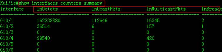
This example displays traffic rate of allports
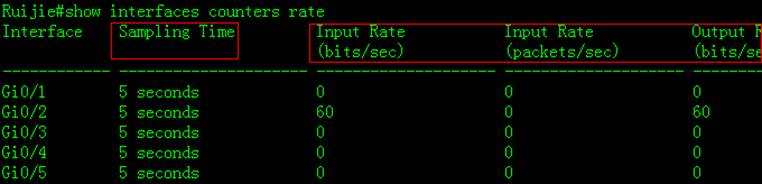

 Thank you. We will inform you of our response as soon as possible.