Terms
WiFi7, commonly referred to as Wi-Fi 7 in network terminology, is the name of IEEE 802.11be.
WiFi6, commonly referred to as Wi-Fi 6 in network terminology, is the name of IEEE 802.11ax.
- Key Technical Features of Wi-Fi 7
There are many key technical features of Wi-Fi 7, but due to limited space, this article will only explore three of them: MLO, Preamble Puncturing, and MRU.
In the initial drafts of the Wi-Fi 7 technical standards, there is a feature known as Multi-AP Coordination technology. However, this feature has been removed in the latest revision of Wi-Fi 7, with plans for its implementation in Wi-Fi 8. This article will not discuss Multi-AP Coordination technology.
3.1 Multi-Link Operation (MLO)
Multi-Link Operation (MLO) allows for multi-link aggregation between a single STA and a single AP that has multiple radio chips, including 2.4 GHz, 5 GHz, and 6 GHz chips. MLO is a MAC layer technology that can aggregate multiple links across different frequency bands into a virtual link.

Two modes are available in MLO: STR mode and NSTR mode.
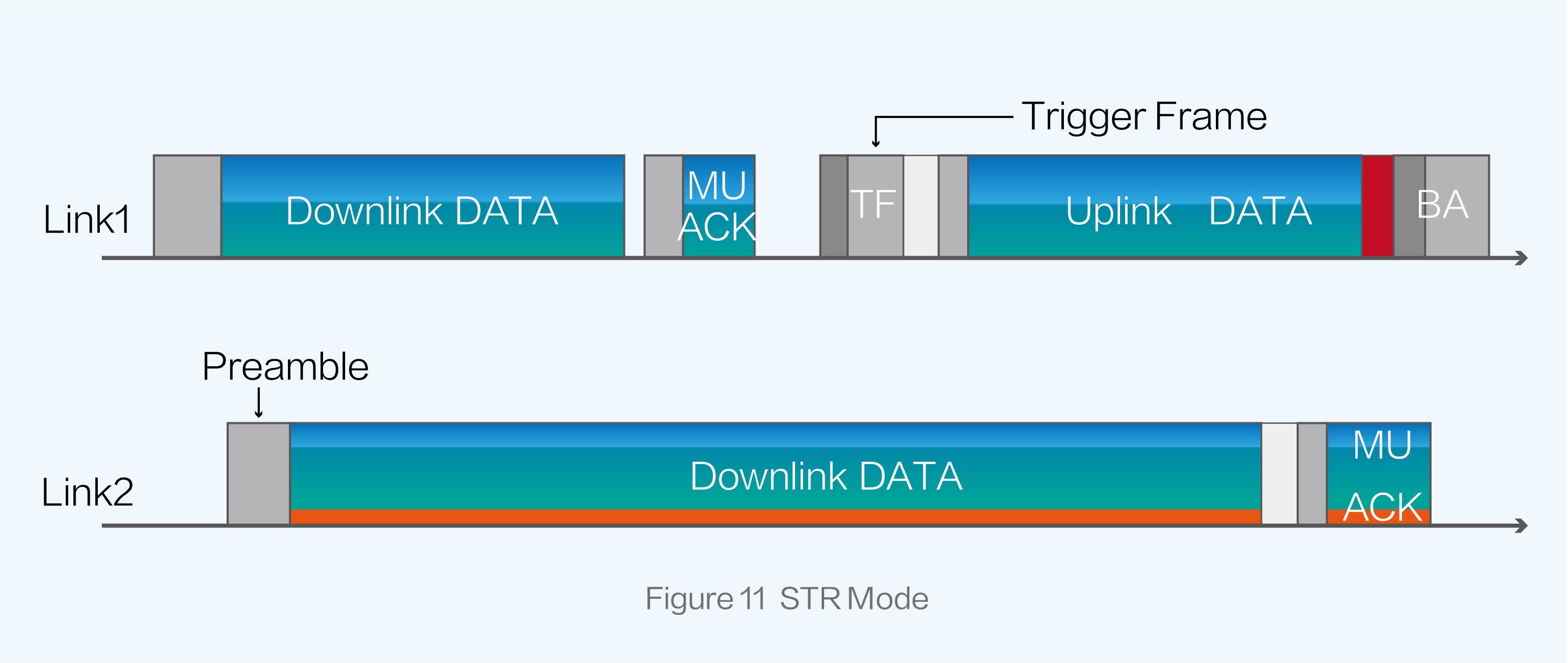
Simultaneous Transmit and Receive (STR) mode is referred to as asynchronous mode. In STR mode, data can be received or transmitted independently over multiple links between an AP and a STA, increasing the transmission rate. That is, Link 1 receives data while Link 2 transmits data simultaneously.
In STR mode, two links where simultaneous receiving and transmitting operations are allowed cannot interfere with each other. This can be achieved by utilizing non-adjacent frequency bands, such as the 2.4 GHz and 5 GHz bands, or by maintaining a certain physical distance between radio chips. If interference occurs between the two links, STR mode is not suitable.
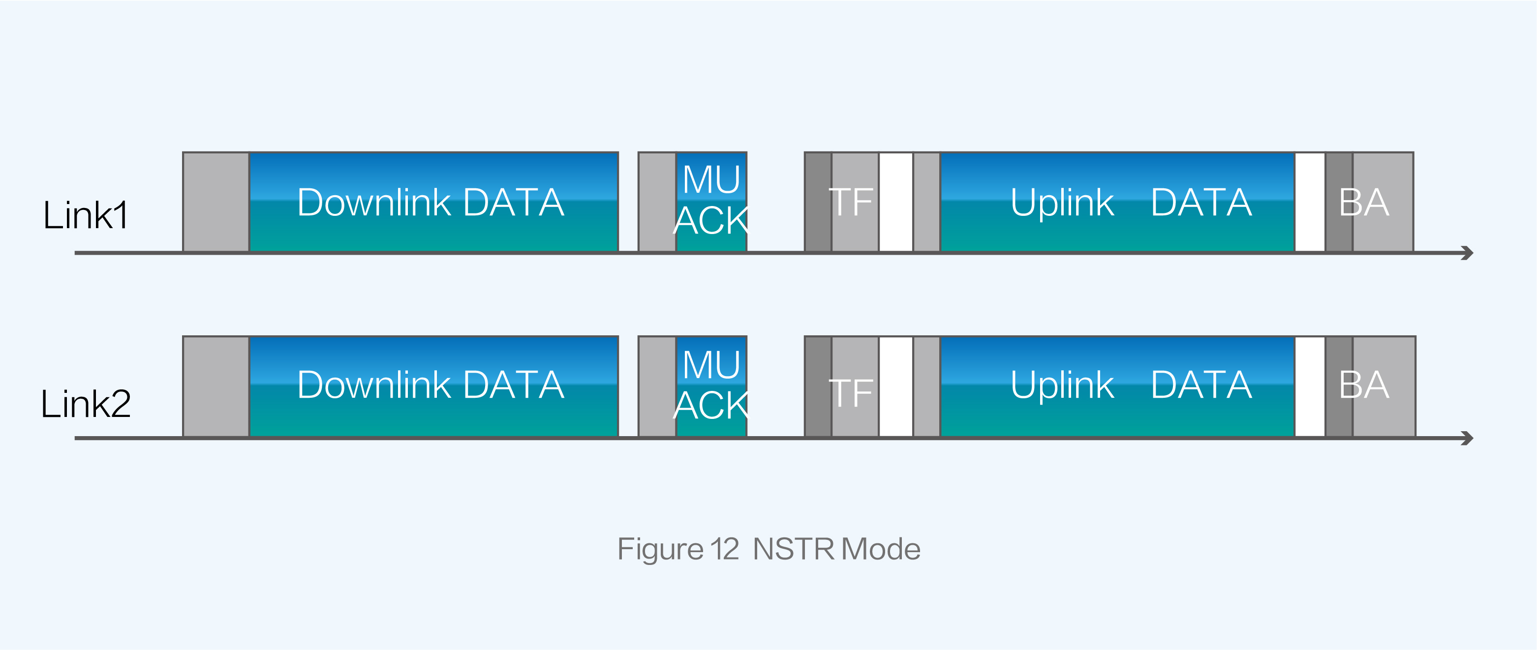
Non-simultaneous Transmit and Receive (NSTR) mode is known as synchronous mode. In NSTR mode, data can only be transmitted or received over multiple links at a single time. Simultaneous receiving and transmitting operations are not allowed, effectively avoiding interference between the links.
MLO enables the establishment of multiple links between an AP and a STA across different frequency bands, greatly enhancing the transmission rate of the AP and reducing latency.
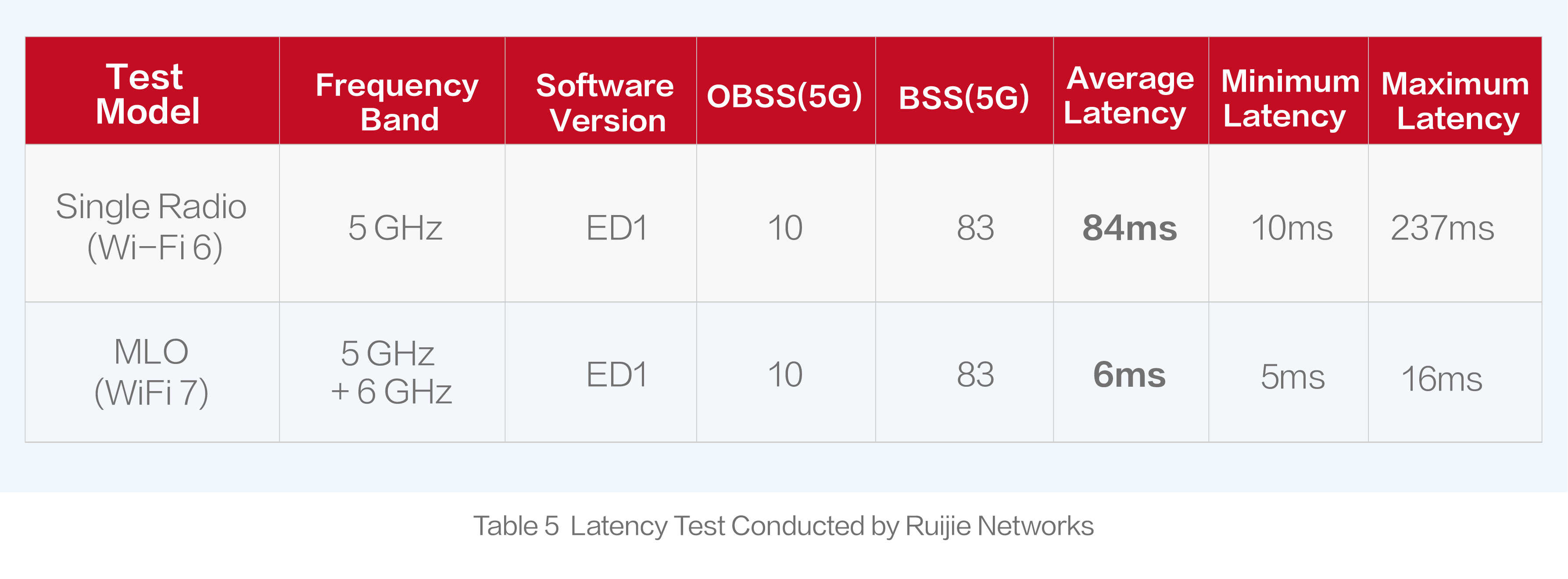
According to the actual tests conducted by Ruijie Networks, its Wi-Fi 7 AP equipped with MLO technology are able to establish two links in the 5 GHz and 6 GHz frequency bands, reducing average latency from 84 ms in Wi-Fi 6 to 6 ms. When the latency is within 10 ms, it is approaching the latency level of wired networks.
What are the similarities and differences between MLO and MU-MIMO?
Similarities
Both MLO and MU-MIMO allow for the establishment of multiple communication links between an AP and a STA, enabling simultaneous data receiving and transmitting operations.
Differences
MU-MIMO is limited to the same radio chip of an AP. For example, eight spatial streams indicate that eight communication links can be established simultaneously between one radio of an AP and one or multiple STAs.
MLO enables the simultaneous establishment of communication links between multiple radios of an AP and the same STA.
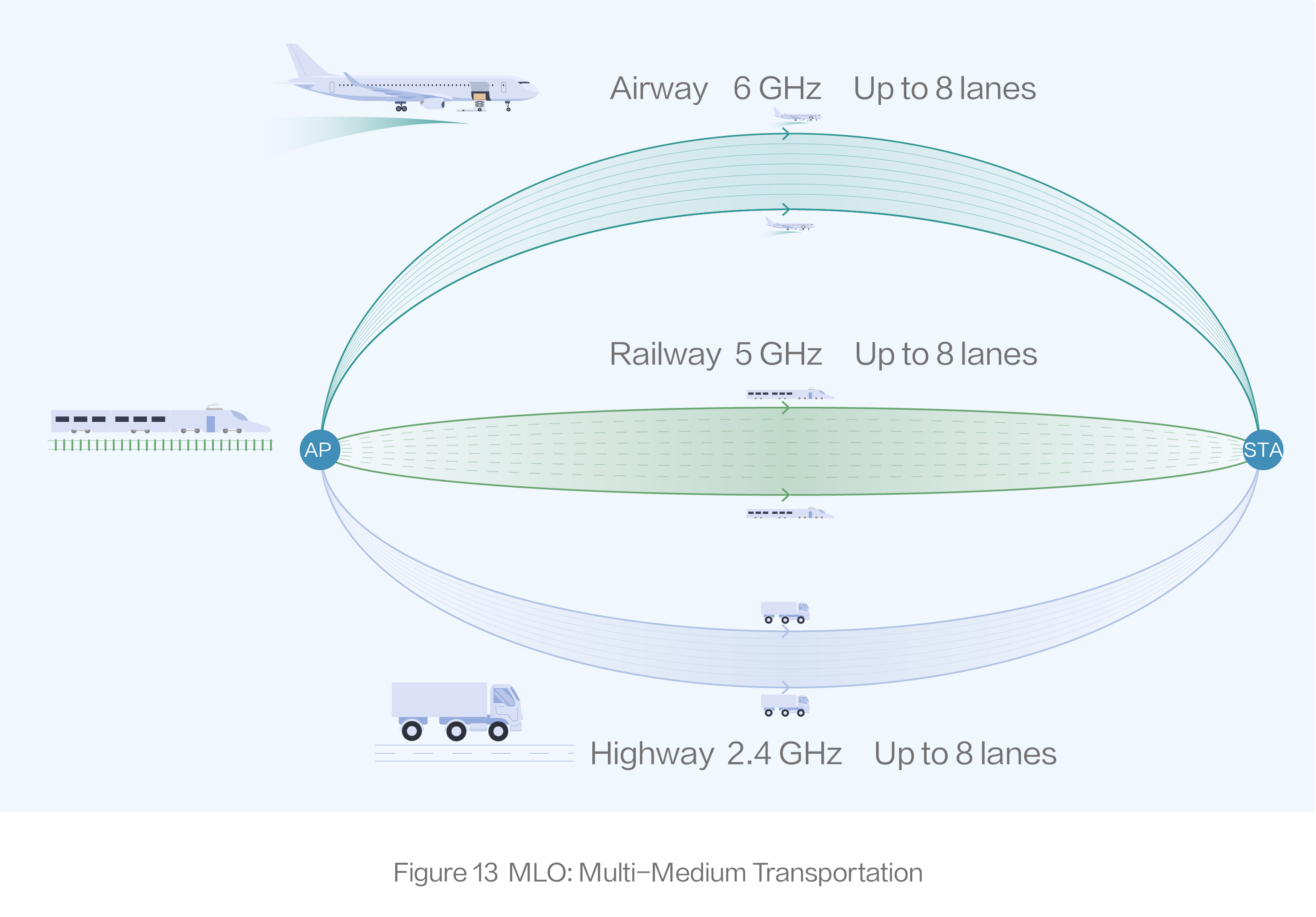
Analogy: An analogy can be made with transportation mediums: railways, highways, and airways. MLO allows for simultaneous communication through all three mediums between an AP and an STA. However, MU-MIMO focuses on a single medium, such as highways, where there are eight lanes available for communication.
3.2 Multiple Resource Unit (MRU)
Multiple Resource Unit (MRU) is a technology that improves spectrum resource efficiency.
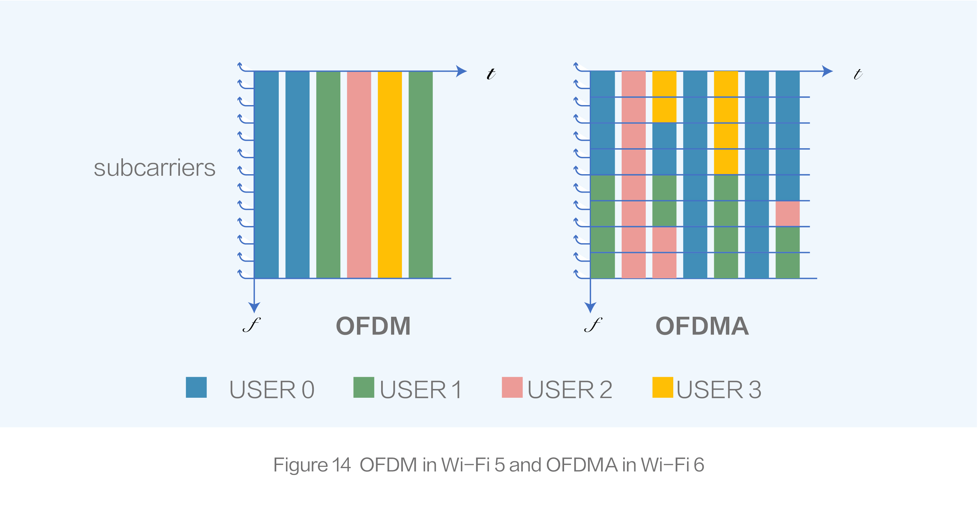
As shown in Figure-14, the left diagram represents the OFDM in Wi-Fi 5. The horizontal axis indicates the time domain while the vertical axis represents the frequency domain. In OFDM that is a single-user transmission technology, each time the data is sent to a single user over a channel. This means that one user occupies the entire channel regardless of the user data amount, resulting in resource wastage.
In the right diagram, Wi-Fi 6 introduces OFDMA in which the resource unit (RU) is the minimum transmission unit. A 20 MHz channel in Wi-Fi 6 can be divided into multiple RUs in the same time domain. With a certain number of tones, each RU is allocated to one user for data transmission. OFDMA allows an AP to communicate with multiple users during one transmission period, greatly increasing resource usage.
The number of tones contained in an RU is not randomly determined. Wi-Fi standards define seven types of RUs: 26-tone RU (containing 26 tones), 52-tone RU, 106-tone RU, 242-tone RU, 484-tone RU, 996-tone RU, and 1992-tone RU.
In Wi-Fi 6, each user is assigned only one RU during one transmission period. Wi-Fi 7 introduces the concept of MRU, enabling the allocation of multiple RUs to a single user during one transmission period.
What is the role of MRU?
Take a scenario where a 20MHz channel needs to be shared among three users as an example. In Wi-Fi 6, the optimal resource allocation is as follows: one user is assigned a 106-tone RU, while the other two users are assigned separate 52-tone RU. 210 subcarriers are allocated, leaving 24 subcarriers unused (a 20MHz channel has a total of 234 valid subcarriers, as mentioned in Basic Concepts of Wi-Fi 7).
With the implementation of MRU in Wi-Fi 7, a 106-tone RU and 26-tone RU combination can be allocated to one user, while 52-tone RUs are allocated to other two users. This makes full use of the resources on the 20 MHz channel, enhancing channel resource usage and throughput while reducing latency.
It is worth noting that not every combination of two RUs can form an MRU. The Wi-Fi 7 standard imposes certain restrictions on RU combination. RUs are categorized into small RUs and large RUs. But small RUs can be combined only with small RUs, while large RUs can be combined only with large RUs.
Small RUs: 26-tone RU, 52-tone RU, and 106-tone RU
Large RUs: 242-tone RU, 484-tone RU, 996-tone RU, and 1992-tone RU
3.3 Preamble Puncturing
Preamble puncturing, also known as puncturing, is an optional technology in Wi-Fi 6. Due to its high technical cost, puncturing is not commonly used in most Wi-Fi 6 products. However, in the Wi-Fi 7 standard, puncturing has evolved into a mandatory requirement for all products.
As mentioned in the first part, channel bonding is used to increase the transmission rate by combining multiple 20 MHz channels into one larger channel. For example, this technology is used to bond eight adjacent 20 MHz channels into a single 160 MHz channel.
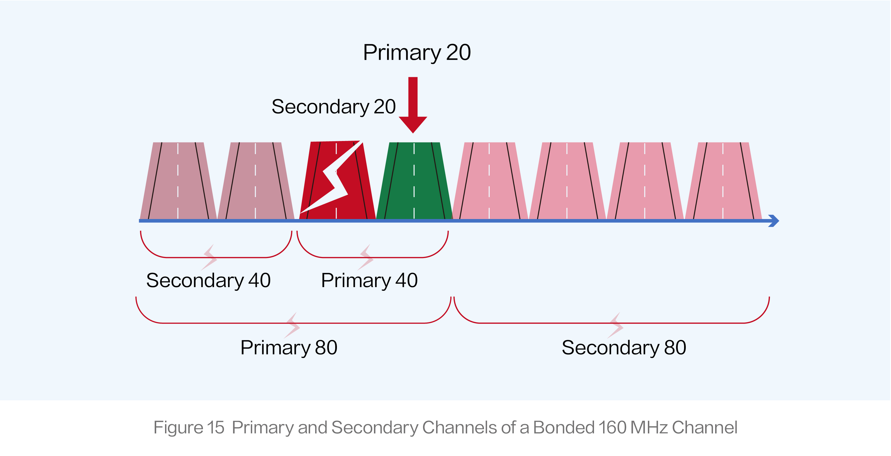
In the channel bonding technology, channels are categorized into primary and secondary channels. When two adjacent 20 MHz channels are bonded into a single 40 MHz channel, a 20 MHz channel becomes the primary 20 MHz channel while the other is designated as the secondary one. These two channels are combined into the primary 40 MHz channel that is further boned with the secondary 40 MHz channel into a single 80 MHz channel (primary 80 MHz channel). The remaining channels are bonded into the secondary 80 MHz channel. Finally, the primary 80 MHz channel and the secondary 80 MHz channel can be bonded into a 160 MHz channel.
The previous protocol specifies two principles for channel bonding. Firstly, only contiguous channels can be bonded together. Secondly, in channel bonding mode, the secondary channels are allowed to transmit information only when the primary channel is free from any interference.
If interference occurs on the secondary 20 MHz channel, the primary 40 MHz channel becomes contaminated, making it impossible to transmit any information on the secondary 40 MHz channel. Moreover, if the interference extends to the primary 80 MHz channel, data transmission are denied on the secondary 80MHz channel. Consequently, when a secondary 20 MHz channel is subject to interference on a bonded 160 MHz channel, only the primary 20 MHz channel is in effect. 7/8 of channel resources are wasted.
To address the issue, Wi-Fi 7 introduces the preamble puncturing mechanism.
Let’s reuse the preceding example. If the secondary 20 MHz channel is subject to interference, puncturing is used to puncture and block this channel. The remaining 140 MHz channels can be still bonded for data transmission. Even though the device still operates in the 160 MHz channel bonding mode, the secondary 20 MHz channel is effectively set to a null state during actual transmission. This improves channel utilization by 600% compared with conventional channel bonding (140:20).
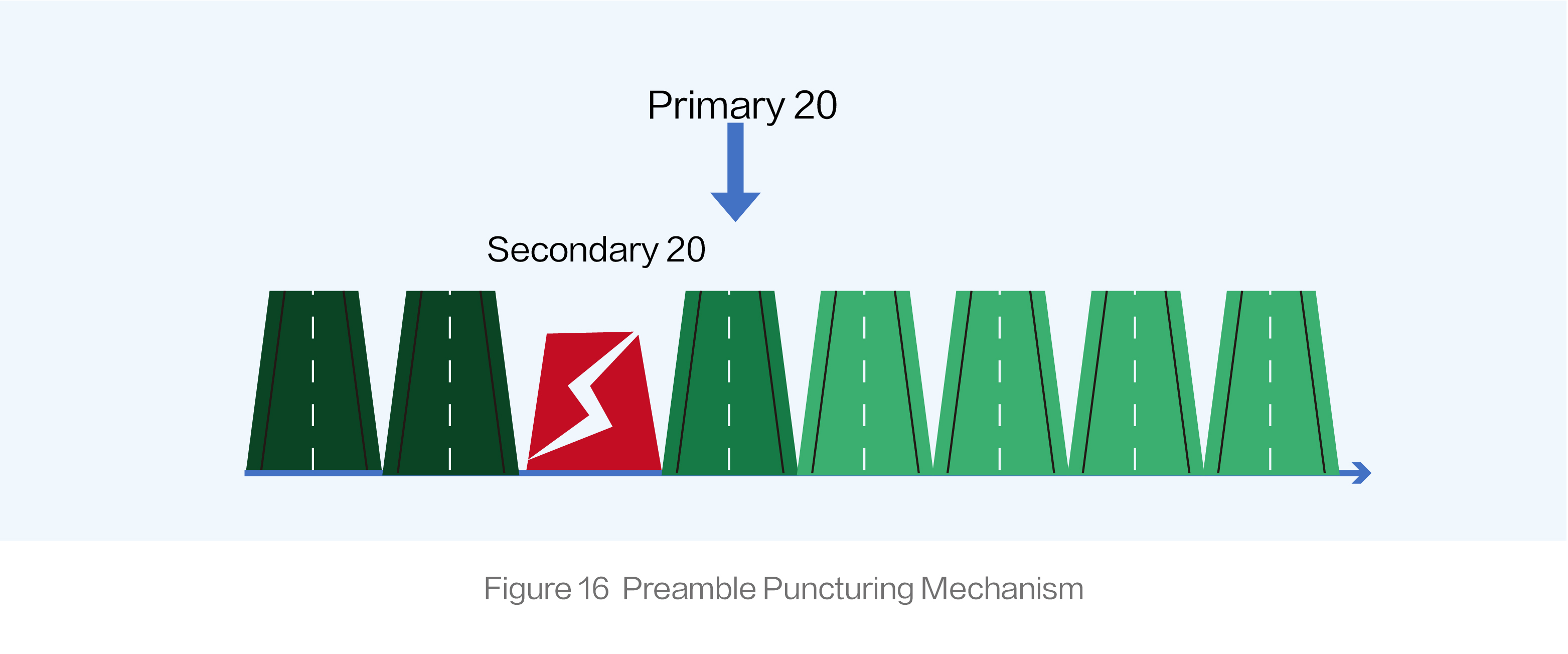
By bonding non-contiguous available channels, preamble puncturing increases channel utilization and actual transmission rate while reducing latency.
- Wi-Fi 7 Application Scenarios
The Wi-Fi Alliance has specified the application scenarios for Wi-Fi 7, including AR/VR/XR, whole-home video distribution, gaming, telemedicine, enterprise, virtual training, education, and hospitality venues.
For those who have read this article, I’m sure you must be interested in Wi-Fi 7 technology. Please feel free to leave comments, engage in discussions, and exchange ideas about technical features, application scenarios, and market aspects of Wi-Fi 7.
Summary
Wi-Fi 7 vs. Wi-Fi 6: Here's What You Need to Know (Part 2) explores the key technical features of Wi-Fi 7, including MLO, Preamble Puncturing, and MRU.

