Ruijie RG-WLAN Implementation Cookbook (V4.1)

Please rate this document.
Please leave your suggestions here.
200 characters leftIf Ruijie may contact you for more details, please leave your contact information here.
* I understand and agree to Terms of Use and acknowledge Ruijie's Privacy Policy.

Thank you for your feedback!


Device Management
1.1 System Management
Default Settings
AC:No default IP address.
AP:Default IP address is 192.168.110.1(or 192.168.1.1), and both console & telnet password are "admin", default enable password is "apdebug"
Following wall AP have different default settings
AP120-W
In Fit mode, IP address of both LAN port and Uplink port IP are 192.168.110.1/24
In Fat mode, IP address of LAN port is 192.168.111.1/24; IP address of Uplink port is 192.168.110.1/24
AP110-W
IP address of Rear panel is 192.168.110.1/24
IP address of Front panel is 192.168.111.1/24
1.1.1 Console Management
Connect cables as below diagram
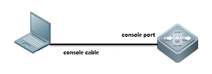
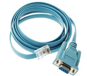
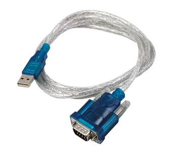
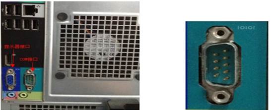
Cables
console cable, USB to RS232 cable
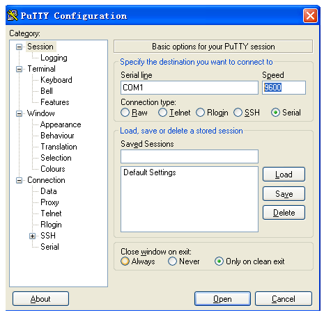
Putty
Open software Putty, set baud rate to 9600
1.1.2 Telnet Management
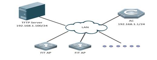
I. Network Topology
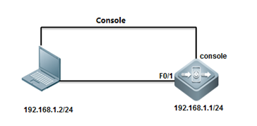
II. Configuration Steps
Configuring Telnet& enable password on AC
Ruijie>enable
Ruijie#configure terminal
Ruijie(config)#interface vlan 1
Ruijie(config-if-vlan 1)#ip address 192.168.1.1 255.255.255.0
Ruijie(config)#ip route 0.0.0.0 0.0.0.0 192.168.1.2
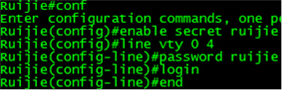
Ruijie(config)#line vty 0 4
Ruijie(config-line)#password ruijie
Ruijie(config-line)#login
Ruijie(config)#enable password ruijie
Configuring Telnet & Enable password on AP
Console connect to device and set passwords, default ap-mode is fit.
User Access Verification
Password: default password is "ruijie"
Ruijie>
Ruijie>enable
Password: default password is "apdebug"
Ruijie#configure terminal
Ruijie(config)#interface bvi 1
Ruijie(config-if-bvi 1)#ip address 192.168.1.1 255.255.255.0
Ruijie(config-if-bvi 1)#interface gigabitEthernet 0/1
Ruijie(config-if-GigabitEthernet 0/1)#encapsulation dot1Q 1
%Warning: Remove all IP address.
Ruijie(config-if-GigabitEthernet 0/1)#exit
Ruijie(config)#ip route 0.0.0.0 0.0.0.0 192.168.1.2
Ruijie(config)#line vty 0 4
Ruijie(config-line)#password ruijie
Ruijie(config-line)#login
Ruijie(config)#enable password ruijie
Note: when ap-mode change from fit to fat, the default password changes as follow:
User Access Verification
Password: default password is "admin"
Ruijie>
Ruijie>enable
Password: no default password
Ruijie#configure terminal
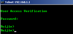
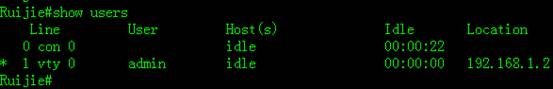
III. Verification
![]()

Save configuration
Ruijie(config)#end
Ruijie#write
Note:
windows7&8 telent client function is not enabled by default, you need to enable the telnet functionality.
Taking Windows 7 as an example:
Control panel - procedures and functions - to open or close the windows function - check the telnet client - select "to determine"
1.1.3 SSH Management
I. Network Topology
II. Configuration Steps
Configuring SSH on AC
Ruijie>enable
Password:
Ruijie#configure terminal
Ruijie(config)#enable service ssh-server
Ruijie(config)#crypto key generate dsa
Choose the size of the key modulus in the range of 360 to 2048 for your
Signature Keys. Choosing a key modulus greater than 512 may take
a few minutes.
How many bits in the modulus [512]:
% Generating 512 bit DSA keys. ..[ok]
Ruijie(config)#interface vlan 1
Ruijie(config-if-VLAN 1)#ip address 192.168.1.1 255.255.255.0
Ruijie(config)#ip route 0.0.0.0 0.0.0.0 192.168.1.2
Ruijie(config)#enable password ruijie
Method 1:Login with password
Ruijie(config)#line vty 0 4
Ruijie(config-line)#password ruijie
Ruijie(config-line)#login
Ruijie(config-line)#end
Ruijie#write
Building configuration...
[OK]
Ruijie#
Method 2:Login with username & password
Ruijie(config)#line vty 0 4
Ruijie(config-line)#login local
Ruijie(config-line)#exit
Ruijie(config)#username admin password ruijie
Ruijie(config)#end
Ruijie#write
Building configuration...
[OK]
Ruijie#
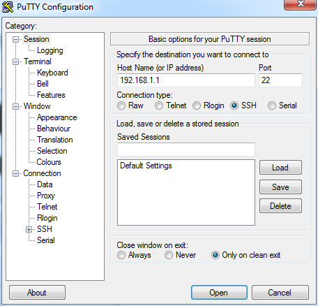
III. Verification
Open Putty, choose Connection type "SSH", input IP address.
To display SSH service status, execute following commands


1.1.4 Web Management
I. Network Topology
II. Configuration Steps
Configuring WEB GUI on AC
Ruijie#configure terminal
Ruijie(config)#enable service web-server
Ruijie(config)#vlan 1
Ruijie(config-vlan)#interface vlan 1
Ruijie(config-if-VLAN 1)#ip address 192.168.1.1 255.255.255.0
Ruijie(config-if-VLAN 1)#exit
Ruijie(config)#webmaster level ?
<0-2> Web auth privilege level (0 is the highest level)
Ruijie(config)#webmaster level 0 username ruijie password ruijie
Ruijie(config)#ip route 0.0.0.0 0.0.0.0 192.168.1.254
Note:
1. AM5528 does not support web management.
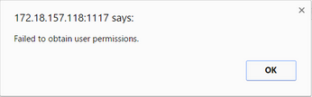
1. Only user “admin” and “ruijie” could be created on cli page, for other account, If you have the web management requirements, please create it on web interface, relative err prompt are shown as follow:
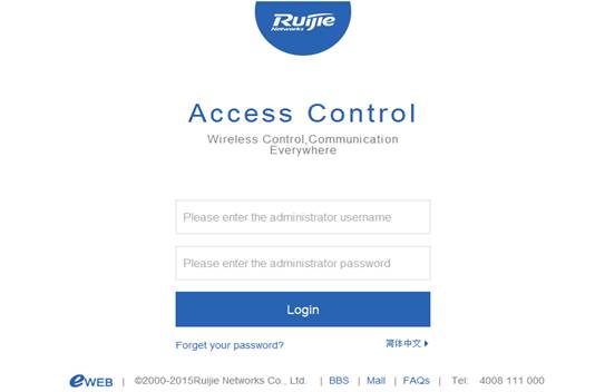
III. Verification
Visit web GUI at http://192.168.1.1, it is recommended that access WEB GUI with IE 8.0 and above version in compatible mode.
1.1.5 Forget IP Address of Wall AP
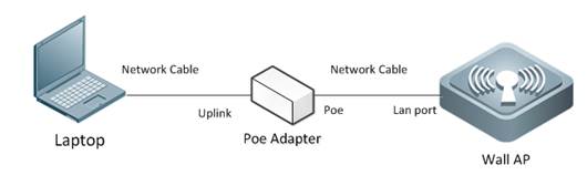
If administrator forgot IP address of Wall-AP, and do not want to recover factory setting, follow below steps:
1. Power on AP, and connect AP as below diagram:
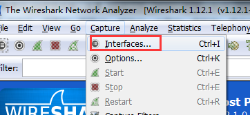
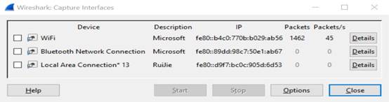
1. Open packet capture tool, here take Wireshark as example:
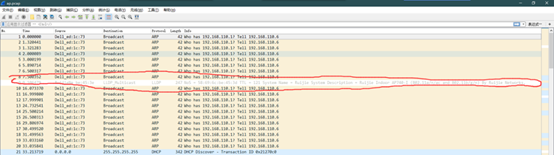
1. Check ARP packets, and 192.168.51.54 is correct IP ![]()
1. Try to telnet AP
1. If above method doesn't work, suggest to restore factory default.
1.2 Firmware Upgrade
1.2.1 Upgrade for RGOS 11.x
1.2.1.1 Upgrade AC & Fit AP (for 11.X)
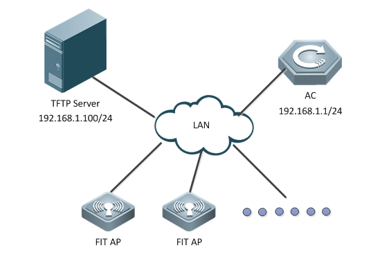
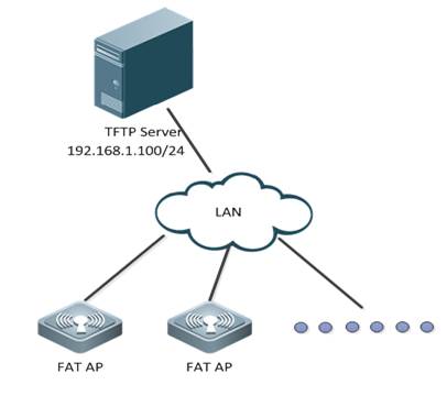
I. Network Topology
II. Requirements
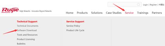
1. Visit official website at www.ruijienetworks.com to request firmware.
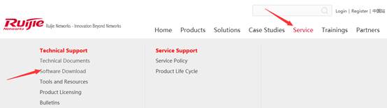
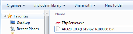
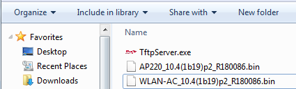
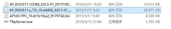
1. Run TFTP Server, and put AP&AC firmware in the same folder. Here take Ruijie TFTPServer as example.
TFTP Server should be able to communicate with AC.
1. AC has built CAPWAP tunnel with APs
1. Read Release Note carefully, pay attention to the "upgrade file"
1. DO NOT restart or POWER OFF AC&AP during upgrades.
1. Login AC CLI via console, telnet or SSH.
III. Configuration Steps
Upgrading AC
Attention:In hot-backup scenario, please remove all networks cables on ACs in case of synchronization issue caused by inconsistent firmware.
1. Display current firmware version and backup relative configuration files.
Ruijie# copy flash:config.text tftp://192.168.1.100/config.text --->backup the configuration files of AC to TFTP Server.
Ruijie# copy flash:ap-config.text tftp://192.168.1.100/ap-config.text ---> backup the configuration of AP to TFTP Server.
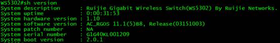
Ruijie#show version detail
System description : Ruijie 10G Wireless Switch(WS6008) By Ruijie Networks.
System uptime : 0:02:15:24
System hardware version: 1.0
System software version: AC_RGOS 11.1(5)B80P3, Release(04131820)
System patch number : NA
System software number : M20361001182017
System serial number : 1234942570002
System boot version : 2.0.19.97cfa98(161210)
System core version : 2.6.32.355270930a6bde
System cpu partition : 4-11
1. Transfer new firmware to AC, execute below commands:
Ruijie#upgrade download tftp://192.168.1.100/rgos.bin
III. Verification
After reloading, execute command "show version" to verify firmware version.
Ruijie#show version detail
System description : Ruijie 10G Wireless Switch(WS6008) By Ruijie Networks.
System uptime : 0:02:15:24
System hardware version: 1.0
System software version: AC_RGOS 11.1(5)B80P3, Release(04131820)
System patch number : NA
System software number : M20361001182017
System serial number : 1234942570002
System boot version : 2.0.19.97cfa98(161210)
System core version : 2.6.32.355270930a6bde
System cpu partition : 4-11
Upgrading Fit APs
Attention:Generally, the fit ap and ac can work normally only when the versions of them are consistent
1. Display current ap firmware version on AC, execute commands "show version all"
Ruijie#show version detail
System description : Ruijie Indoor AP330-I (802.11a/n and 802.11b/g/n) By Ruijie Networks.
System start time : 1969-12-31 23:59:59
System uptime: 0:00:01:09
System hardware version: 1.10 ------>hardware version
System software version: AP_RGOS 11.1(5)B3, Release(02160403)------>software version
System patch number : NA
System software number : M03112104042015
System serial number: G1GDB16019485
System boot version : 1.1.1.6822c2a(140920)
System core version : 2.6.32.ab930e7d22374b
1. To transfer AP new firmware to AC, execute below commands:
Ruijie#copy tftp://192.168.1.100/330.bin flash:330.bin
Press Ctrl+C to quit
!!!!!!!!!!!!!!!!!!!!!!!!!!!!!!!!!!!
Copy success
1. To configure ap-serial, execute below commands:
Ruijie(config)#ac-controller
Ruijie(config-ac)#active-bin-file flash:330.bin
Ruijie(config-ac)#ap-image auto upgrade
1. After AP reloading, APs will establish CAPWAP tunnel with AC.
III. Verification
1. Display AP upgrading progress, execute commands "show ap-config updating-list"
Ruijie#show ap-config updating-list
AP NAME AP PID File Tx Time AP Reset Ready
---------------------- --------------- -------- ------------ -----------
AP330-I AP330-I 20 % 00:00:06 N
1. Display current ap firmware version on AC, execute commands "show version all"
Ruijie>show version
System description : Ruijie Indoor AP330-I (802.11a/n and 802.11b/g/n) By Ruijie Networks.
System start time : 1970-01-01 00:00:01
System uptime: 0:00:01:52
System hardware version: 1.10
System software version: AP_RGOS 11.1(5)B5, Release(02182520)
System patch number : NA
System serial number: G1GDB16019485
System boot version : 1.1.1
1.2.1.2 Upgrade Fat AP (for 11.X)
I. Network Topology

II. Requirements
1. Visit official website at www.ruijienetworks.com to request firmware.
1. Run TFTP Server, and put AP firmware in the same folder. Here take Ruijie TFTPServer as example.
TFTP Server should be able to communicate with AP.
1. Read Release Note carefully, pay attention to the "upgrade file"
1. DO NOT restart or POWER OFF AP during upgrades.
1. Login AP CLI via console, telnet or SSH.
Attention: Wall APs, like AP130 (W2) & AP130L, do not have console port. See Device Management -->Conventions to learn the default IP address.
III. Configuration Steps
Upgrading FAT APs
1. Backup configuration files to TFTP Server, and display current firmware version
Ruijie#copy flash:config.text tftp://192.168.1.100/config.text --->backup configuration files of AP to TFTP Server
Ruijie#show version detail ---> check version
System description : Ruijie Indoor AP330-I (802.11a/n and 802.11b/g/n) By Ruijie Networks.
System start time : 1969-12-31 23:59:59
System uptime: 0:00:01:09
System hardware version: 1.10
System software version: AP_RGOS 11.1(5)B3, Release(02160403)
System patch number : NA
System software number : M03112104042015
System serial number : G1GDB16019485
System boot version : 1.1.1.6822c2a(140920)
System core version : 2.6.32.ab930e7d22374b
1. Display current ap mode
AP320#show ap-mode
current mode: fat
AP320#
1. Transfer new firmware to AP, execute below commands:
Ruijie#upgrade download tftp://192.168.1.100/330-b5.bin
Upgrade the device must be auto-reset after finish, are you sure upgrading now?[Y/n]y
Running this command may take some time, please wait.
Please wait for a moment......
Press Ctrl+C to quit
!!!!!!!!!!!!!!!!!!!!!!!.!!!!!!!!!.!!!
Begin to upgrade the install package 330-b5.bin... --->reload automatically
*Jan 1 00:03:52: %7: Upgrade processing is 10%
Uncompress file 330-b5.bin. .......
IV. Verification
After reloading, execute command "show version" to verify firmware version.
Ruijie#show version detail
System description : Ruijie Indoor AP330-I (802.11a/n and 802.11b/g/n) By Ruijie Networks.
System start time : 1970-01-01 00:00:01
System uptime: 0:00:01:09
System hardware version: 1.10
System software version: AP_RGOS 11.1(5)B5, Release(02182520)
System patch number : NA
System software number : M20085306252015
System serial number : G1GDB16019485
System boot version : 1.1.1.6822c2a(140920)
System core version : 2.6.32.720c78d1a03d63
1.2.2 Upgrade from RGOS 10.x to 11.x
1.2.2.1 Upgrade AC & Fit AP from 10.X to 11.X
I. Network Topology
II. Requirements
1. Visit official website at www.ruijienetworks.com to request firmware.. 
1. Run TFTP Server, and put AP&AC firmware in the same folder. Here take Ruijie TFTPServer as example.
TFTP Server should be able to communicate with AC.
1. AC has built CAPWAP tunnel with APs
1. Read Release Note carefully, pay attention to the "upgrade file"
1. DO NOT restart or POWER OFF AC&AP during upgrades.
1. Login AC CLI via console, telnet or SSH.
III. Configuration Steps
Upgrading AC
Attention:In hot-backup scenario, please remove all networks cables on ACs in case of synchronization issue caused by inconsistent firmware.
1. Display current firmware version and backup relative configuration files.
Ruijie#copy flash:config.text tftp://172.18.158.204/config.text --->backup the configuration files of AC to TFTP Server.
Ruijie#copy flash:ap-config.text tftp://172.18.158.204/ap-config.text ---> backup the configuration of AP to TFTP Server.
1. Transfer new firmware to AC, execute below commands:
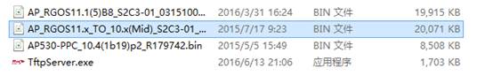
Ruijie#copy tftp://172.18.158.204/AC_RGOS10.x_TO_11.x(Mid)_G1C5-01_02172111.bin flash:rgos.bin
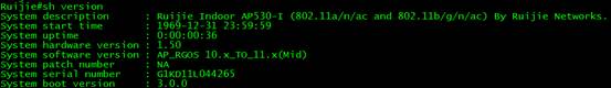
After reloading, execute command "show version" to verify firmware 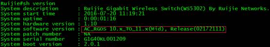
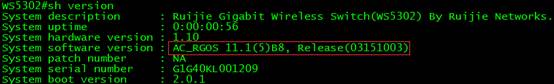
1. Because the configuration files will lost when upgrade to mid version, need to import the config.text, and test the connection between AC and terminal, then Downgrade AC to target version 11.x
Ruijie#upgrade download tftp://192.168.1.100/AC_RGOS11.1(5)B8_G1C5-01_03151003_install.bin
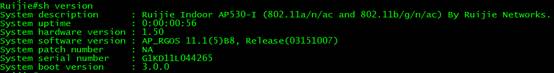
IV. Verification
After reloading, execute command "show version" to verify firmware version
Upgrading Fit APs
1. Transfer 11.x and mid version of AP to AC, execute below commands:
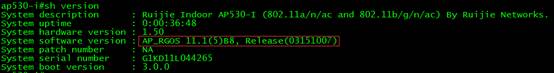
Ruijie#copy tftp://172.18.158.204/AP_RGOS10.x_TO_11.x(Mid)_S2C3-01_02201910.bin flash:ap530-mid.bin
Ruijie#copy tftp://172.18.158.204/AP_RGOS11.1(5)B8_S2C3-01_03151007_install.bin flash:ap530.bin
1. To configure ap-serial, execute below commands:
Ruijie(config)#ac-controller
Ruijie(config-ac)#active-bin-file ap530-mid.bin rgos10
Ruijie(config-ac)#active-bin-file ap530.bin
Ruijie(config-ac)#ap-serial ap530 AP530-I hw-ver 1.x
Ruijie(config-ac)#ap-image ap530-mid.bin ap530
Ruijie(config-ac)#ap-image ap530.bin ap530
IV. Verification
1. After reloading, execute command "show version" to verify firmware version
1. After AP reloading, APs will build CAPWAP tunnel with AC.

1.2.2.2 Upgrade Fat AP from 10.X to 11.X
I. Network Topology
II. Requirements
1. Visit official website at www.ruijienetworks.com to request firmware.
1. Run TFTP Server, and put AP firmware in the same folder. Here take Ruijie TFTPServer as example.
TFTP Server should be able to communicate with AP.
1. Read Release Note carefully, pay attention to the "upgrade file"
1. DO NOT restart or POWER OFF AP during upgrades.
1. Login AP CLI via console, telnet or SSH.
Attention: Upgrade from 10.X to 11.X, configuration will lost, backup the configuration before downgrading; need to downgrade to mid version first.
III. Configuration Steps
Upgrading FAT APs
1. Backup configuration files to TFTP Server, and display current firmware version
Ruijie#copy flash:config.text tftp://192.168.111.2/config.text --->backup configuration files of AP to TFTP Server
1. Display current ap mode
Ruijie#show ap-mode
current mode: fat
1. Transfer new firmware to AP, execute below commands:
Ruijie#copy tftp://192.168.111.2/AP_RGOS10.x_TO_11.x(Mid)_S2C3-01_02201910.bin flash:rgos.bin
Upgrade the device must be auto-reset after finish, are you sure upgrading now?[Y/n]y
Running this command may take some time, please wait.
Please wait for a moment......
Press Ctrl+C to quit
!!!!!!!!!!!!!!!!!!!!!!!!!!!!!!!!!!!!!!!!
Verification
1. downgrade to target version 11.x
Ruijie# upgrade download tftp://192.168.111.2/AP_RGOS11.1(5)B8_S2C3-01_03151007_install.bin
1. reload and verification
1.2.3 Downgrade from RGOS 11.x to 10.x
1.2.3.1 Downgrade the AC & Fit AP from 11.X to the 10.X
I. Network Topology
II. Requirements
1. Visit official website at www.ruijienetworks.com to request firmware.

1. Run TFTP Server, and put AP firmware in the same folder. Here take Ruijie TFTPServer as example.
TFTP Server should be able to communicate with AP.
1. Read Release Note carefully, pay attention to the "upgrade file"
1. DO NOT restart or POWER OFF AP during upgrades.
1. Login AP CLI via console, telnet or SSH.
Attention: Downgrade from 11.X to 10.X, configuration will lost, backup the configuration before downgrading; need to downgrade to mid version first.
III. Configuration Tips
Downgrading FIT APs
1. Backup configuration files on ac
1. Transfer mid version of AP to AC
TFTP Server should be able to communicate with AC.
1. Active version of AP
1. Read Release Note carefully, pay attention to the "downgrade file"
1. DO NOT restart or POWER OFF AC&AP during upgrades.
1. Login AC CLI via console, telnet or SSH.
IV. Configuration Steps
Downgrading AC
Attention:In hot-backup scenario, please remove all networks cables on ACs in case of synchronization issue caused by inconsistent firmware.
1. Display current firmware version
Downgrading Fit APs
1. To transfer AP new firmware to AC, execute below commands:
Ruijie#copy tftp://192.168.1.100/AP_RGOS11.1(2)B1_AP320_v2.0_degrade.bin flash:320-mid.bin
2 To configure ap-serial, execute below commands:
Ruijie#config terminal
Ruijie(config)#ac-controller
Ruijie(config-ac)#active-bin-file 320-mid.bin
Ruijie(config-ac)#ap-serial ap320 AP320-I hw-ver 1.x
Ruijie(config-ac)#ap-image ap320-mid.bin ap320
Ruijie(config-ac)#end
Ruijie#wr
1. telnet APs and verify the current version
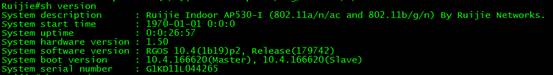
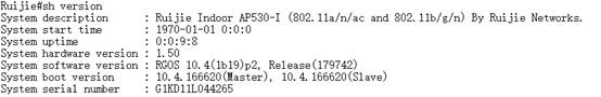
Ruijie#show version
System description : Ruijie Indoor AP320-I (802.11a/n and 802.11b/g/n) By Ruijie Networks.
System start time : 1970-01-01 0:0:0
System uptime: 0:0:0:44
System hardware version: 1.10
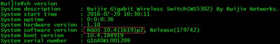
System software version: RGOS 10.4(1b19)p2, Release(175879)
System boot version : 10.4.155446(Master), 10.4.155446(Slave) -àmid version of AP
System serial number : G1GDC13025434
1. Downgrade AC from 11.X to 11.X_to_10.X(Mid), execute below commands:
Ruijie#upgrade download tftp://172.18.158.204/AC_RGOS11.x_TO_10.x(Mid)_G1C5-02_02172016.bin force
Verification
After reloading, execute command "show version" to verify firmware 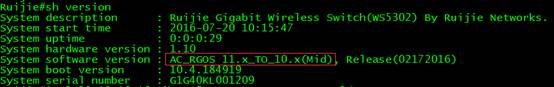
1. Because the configuration files will lost when downgrade to mid version, need to import the config.text, and test the connection between AC and terminal, then Downgrade AC to target version 10.x
Ruijie#copy tftp://172.18.158.205/WLAN-AC-50XX_10.4(1b19)p2_R179742.bin flash:rgos.bin
Ruijie#reload
Verification
1. After downgrading the AC, the configuration will loss, need to import the ac configuration.
Ruijie#copy tftp://192.168.1.100/config.text flash:config.text
Ruijie#copy tftp://192.168.1.100/ap-config.text flash:ap-config.text
Ruijie#reload
1. Downgrade AP to target version 10.x
Ruijie#copy tftp://192.168.1.100/AP320_10.4(1b19)p2_R179742.bin flash 320I.bin
Ruijie#configure terminal
Ruijie(config)#ac-controller
Ruijie(config-ac)#active-bin-file 320I.bin
Ruijie(config-ac)#ap-serial ap320 AP320-I hw-ver 1.x
Ruijie(config-ac)#ap-image 320I.bin ap320
Ruijie(config-ac)#end
Ruijie#wr
V. Verification
Ruijie#show version
System description : Ruijie Indoor AP320-I (802.11a/n and 802.11b/g/n) By Ruijie Networks.
System start time : 2015-01-05 12:37:41
System uptime: 4:0:24:8
System hardware version: 1.10
System software version: RGOS 10.4(1b19)p2, Release(179742)
System boot version : 10.4.155446(Master), 10.4.155446(Slave)
System serial number : G1GD91300419A
1.2.3.2 Downgrade the Fat AP from 11.X to the 10.X
I. Network Topology
II. Requirements
1. Visit official website at www.ruijienetworks.com to request firmware.

1. Run TFTP Server, and put AP firmware in the same folder. Here take Ruijie TFTPServer as example.
TFTP Server should be able to communicate with AP.
1. Read Release Note carefully, pay attention to the "upgrade file"
1. DO NOT restart or POWER OFF AP during upgrades.
1. Login AP CLI via console, telnet or SSH.
Attention: Downgrade from 11.X to 10.X, configuration will lost, backup the configuration before downgrading; need to downgrade to mid version first.
III. Configuration Steps
Downgrading FAT APs
1. Backup configuration files to TFTP Server, and display current firmware version
Ruijie#copy flash:config.text tftp://192.168.111.2/config.text --->backup configuration files of AP to TFTP Server
1. Display current ap mode
Ruijie#show ap-mode
current mode: fat
1. Transfer new firmware to AP, execute below commands:
Ruijie#upgrade download tftp://192.168.111.2/AP_RGOS11.x_TO_10.x(Mid)_S2C3-01_02180712.bin
Upgrade the device must be auto-reset after finish, are you sure upgrading now?[Y/n]y
Running this command may take some time, please wait.
Please wait for a moment......
Press Ctrl+C to quit
!!!!!!!!!!!!!!!!!!!!!!!!!!!!!!!!!!!!!!!!
*Jan 1 00:04:27: %7:
*Jan 1 00:04:27: %7: Begin to upgrade the install package AP_RGOS11.x_TO_10.x(Mid)_S2C3-01_02180712.bin...
*Jan 1 00:04:27: %7: Upgrade processing is 10%
RG-UPGRADE:package.c:621]Old md5 value(/rootfs.ubi):
[RG-UPGRADE:rpm_opt.c:374]:e2d4e747428247db1ca518ade88d0bb1
Verification
1. downgrade to target version 10.x
Ruijie#copy tftp://192.168.111.2/AP530-PPC_10.4(1b19)p2_R179742.bin flash:rgos.bin
1. reload and verification
1.2.4 Recover Firmware under BOOT
1.2.4.1 AC & AP with Console Port
I. Network Topology
II. Requirements
1. Generally, we recover firmware under BOOT mode if we deletes firmware on Main Mode by mistake, firmware broken or any other unknown reasons that devices cannot boot up and enter Main Mode.
1. Finish reading Device Management --> System Management --> Firmware Upgrade, have knowledge of how to transfer firmware with TFTP server.
1. It's applicable for both AC and APs with console port. Not applicable for Wall APs without console port.
Note: remember to turn off Windows Defender protection and system firewall.
III. Configuration Steps
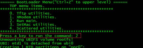
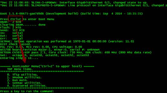
1. Restart devices, press "CTRL + C" when system prompts, enter BOOT Mode, Input 0
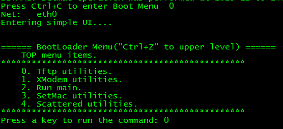
1. Input 1, then upgrade firmware with the following steps.
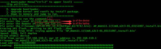
1. Input "yes"

1. Press "CTRL+Z" return to upper level, then choose "2" to run main
IV. Verification
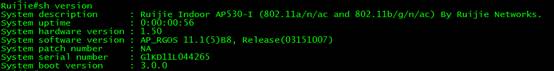
Devices succeed to enter Main mode, execute command "show version", check the firmware version.
Ruijie#show version
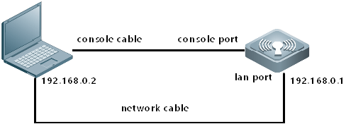
1.2.4.2 Wall AP without Console Port
I. Network Topology

II. Requirements
1. Generally, we recover firmware under BOOT mode if we deletes firmware on Main Mode by mistake, firmware broken or any other unknown reasons that devices cannot boot up and enter Main Mode.
1. Finish reading Device Management --> System Management & --> Firmware Upgrade, have knowledge of how to transfer firmware with TFTP server.
III. Configuration Steps
1. Open Wireshark, load a packet capture process as below. AP 192.168.64.163 lost firmware and is requesting 192.168.64.1 for firmware.
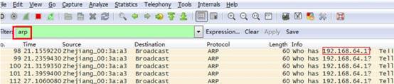
1. Assign IP address 192.168.64.1 to laptop, enable TFTP Server and also prepare the firmware.

1. Edit a notepad name as "FileList.txt", put it in the same folder as shown above, the content is the firmware name you're going to transfer

1. AP will begin downloading firmware soon, verify by viewing TFTP Server connection status.
1. AP will reload when finish recovering firmware
IV. Verification
Login AP via telnet and AP is recovered.
1.3 Password Recovery
1.3.1 Recover AC &Fat AP password
I. Network Topology
II. Requirements
1. Finish reading System Management --> Console Management.
1. Login AC CLI via Console.
III. Configuration Steps
Recovering AC password (configuration file remains)
1. Power off AC, then power up.
1. Press CTRL + C, enter CTRL mode.
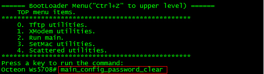
1. Input CTRL+Q, enter uboot mode. And then input "main_config_password_clear"
1. Device will reload automatically.
1. When finish reloading, enter CLI without input password.
![]()
Note: The default timeout period is 10min. Please change your password before time out.
1. Change password, and then use the command “wr” to save your configuration.
1. save configuration

Re-login AC, execute commands "show runing-config" to check configurations.
1.4 Restore Factory Default
1.4.1 Restoring AC & FAT AP
I. Requirements
1. Finish reading Device Management --> System Management
1. Login CLI via console, telnet or SSH
II. Configuration Steps
Execute command "dir" to check file system
Ruijie#dir
Mode Link Size MTime Name
-------- ---- --------- ------------------- ------------------
1 1600 1970-01-02 01:31:10 config.text
1 11729 2015-06-18 02:03:26 cw_teardown_info.txt
<DIR> 1 0 1970-01-01 00:00:00 dev/
1 33 2015-06-03 00:04:25 dhcp_bind.dat
<DIR> 4 0 1970-01-01 00:00:18 pkistore/
<DIR> 5 0 1970-01-01 00:00:11 portal/
<DIR> 0 0 1970-01-01 00:00:00 proc/
<DIR> 1 0 1970-01-01 00:00:01 ram/
1 1529 2015-03-09 16:31:28 reset.txt
1 8359680 2015-03-09 16:31:26 rgos.bin
<DIR> 2 0 1970-01-01 00:00:08 tmp/
1 150740 1970-01-01 00:00:12 ucs_big5.db
1 239708 1970-01-01 00:00:12 ucs_gb.db
<DIR> 4 0 1970-01-01 00:00:12 web/
1 2766752 1970-01-01 00:00:10 web_management_pack.upd
--------------------------------------------------------------
12 Files (Total size 12243866 Bytes), 7 Directories.
Total 132120576 bytes (126MB) in this device, 115515392 bytes (110MB) available.
"config.text" is configuration file, execute commands "del config.text" to set factory default
Ruijie#del config.text
Are you sure you want to delete "config.text"?[Yes/No]y
Ruijie#reload
Processed with reload? [no]y
After reloading, execute commands "show running-config" to check configuration.
1.4.2 Restoring FIT AP
I. Requirements
1. Finish reading Device Management --> System Management
1. Login CLI via console, telnet or SSH
II. Configuration Steps
Restore Factory Default
AC#conf t
AC(config)#ac-controller
AC(config-ac)#reset ?
all Reset the all APs in this AC.
single Reset the single ap.
Then the fit ap will restart automatically.
III. Verification
After reloading, execute commands "show running-config" to check configuration.
1.4.3 Restoring WALL AP
Especially, for Wall AP including AP110W, AP120W, AP130W
Long press "reset" button more than 8 seconds to set factory default.
1.5 Backup Configuration
1.5.1 Backup to Flash
I. Requirements
1. Finish reading System Management
1. Login device CLI via Console, telnet or SSH.
II. Configuration Steps
Execute command "dir" to check file system
WS6008#dir
Directory of flash:/
Number Properties Size Time Name
------ ---------- ------ ------------------------ --------------------
1 drwx 160B Mon Oct 10 19:27:37 2016 dev
2 drwx 160B Mon Mar 21 17:32:15 2016 rep
3 drwx 224B Mon Mar 21 17:32:16 2016 var
4 drwx 160B Mon Oct 10 19:27:40 2016 addr
5 -r-- 4.1k Wed Nov 2 16:27:00 2016 tmp_env.txt
6 -rwx 5.0k Mon Mar 21 17:32:36 2016 hwd.db
7 -rw- 2.9k Tue Oct 11 12:39:39 2016 virtual_switch.text
8 drwx 304B Mon Mar 21 17:32:42 2016 security
9 -rwx 180B Fri Nov 4 16:48:45 2016 config_vac.dat
10 -rw- 14.8k Fri Nov 4 16:48:46 2016 config.text
11 -rwx 384B Thu Sep 29 10:21:54 2016 LIC-WLAN-AP-3200000003956646.lic
12 -rwx 18B Mon Sep 26 17:35:26 2016 test.txt
13 -rw- 718B Tue Oct 11 09:14:18 2016 ap-standalone.text
14 -rwx 696B Mon Mar 21 17:32:30 2016 httpd_cert.crt
15 -rwx 21B Fri Nov 4 16:48:45 2016 syslog_rfc5424_flag.txt
16 drwx 424B Tue Mar 29 16:50:43 2016 portal
17 -rwx 44.4M Mon Oct 31 18:20:17 2016 AM_RGOS11.1(5)B9_G1B5-01_03211300_install.bin
18 -rwx 620B Tue Oct 11 12:39:27 2016 rsa_private.bin
19 -rwx 336B Sun Oct 30 15:32:36 2016 dsa_private.bin
20 -rw- 5.8k Thu Jun 30 14:35:03 2016 text.bak
21 -rwx 384B Wed Oct 12 17:17:05 2016 LIC-WLAN-AP-3200000003466646.lic
22 drwx 296B Thu Oct 13 13:45:02 2016 upgrade
23 drwx 160B Fri Nov 4 09:36:26 2016 tech_vsd0
24 drwx 448B Thu Sep 29 11:24:06 2016 rg_licns
25 drwx 312B Mon Oct 10 19:57:36 2016 syslog
26 -rw- 147B Tue Oct 11 12:39:39 2016 ap-virtual_switch.text
27 -rw- 723B Fri Nov 4 16:48:46 2016 ap-config.text
28 -rwx 187.1k Fri Nov 4 18:27:03 2016 log-13-may-5.txt
29 -rwx 77.8M Mon Oct 31 20:23:11 2016 AC_RGOS11.1(5)B9_G2C6-01_03201812_install.bin.up.tmp
30 -rwx 887B Mon Mar 21 17:32:30 2016 httpd_key.pem
31 -rw- 8.9k Tue Oct 11 09:14:18 2016 standalone.text
21 files, 10 directories
281,903,104 bytes data total (155,267,072 bytes free)
536,870,912 bytes flash total (155,267,072 bytes free)
"config.text" is configuration file, execute commands "copy flash:config.text flash:config.bak" to backup configuration file
"ap-config.text" is ap configuration file, execute commands "copy flash:ap-config.text flash:ap-config.bak" to backup ap configuration file
Ruijie#
Ruijie#copy flash:config.text flash:config.bak
Ruijie#copy flash:ap-config.text flash:ap-config.bak
III. Verification
To view backup file, execute command "dir" to display filesystem. The file size should match.
WS6008#dir
Directory of flash:/
Number Properties Size Time Name
------ ---------- ------ ------------------------ --------------------
1 drwx 160B Mon Oct 10 19:27:37 2016 dev
2 drwx 160B Mon Mar 21 17:32:15 2016 rep
3 drwx 224B Mon Mar 21 17:32:16 2016 var
4 drwx 160B Mon Oct 10 19:27:40 2016 addr
5 -r-- 4.1k Wed Nov 2 16:27:00 2016 tmp_env.txt
6 -rwx 5.0k Mon Mar 21 17:32:36 2016 hwd.db
7 -rw- 2.9k Tue Oct 11 12:39:39 2016 virtual_switch.text
8 drwx 304B Mon Mar 21 17:32:42 2016 security
9 -rwx 180B Fri Nov 4 16:48:45 2016 config_vac.dat
10 -rw- 14.8k Fri Nov 4 16:48:46 2016 config.text
11 -rwx 384B Thu Sep 29 10:21:54 2016 LIC-WLAN-AP-3200000003956646.lic
12 -rwx 18B Mon Sep 26 17:35:26 2016 test.txt
13 -rw- 718B Tue Oct 11 09:14:18 2016 ap-standalone.text
14 -rwx 696B Mon Mar 21 17:32:30 2016 httpd_cert.crt
15 -rwx 21B Fri Nov 4 16:48:45 2016 syslog_rfc5424_flag.txt
16 drwx 424B Tue Mar 29 16:50:43 2016 portal
17 -rwx 44.4M Mon Oct 31 18:20:17 2016 AM_RGOS11.1(5)B9_G1B5-01_03211300_install.bin
18 -rwx 620B Tue Oct 11 12:39:27 2016 rsa_private.bin
19 -rwx 336B Sun Oct 30 15:32:36 2016 dsa_private.bin
20 -rw- 14.8k Fri Nov 4 19:08:10 2016 config.bak
21 -rw- 5.8k Thu Jun 30 14:35:03 2016 text.bak
22 -rwx 384B Wed Oct 12 17:17:05 2016 LIC-WLAN-AP-3200000003466646.lic
23 drwx 296B Thu Oct 13 13:45:02 2016 upgrade
24 drwx 160B Fri Nov 4 09:36:26 2016 tech_vsd0
25 drwx 448B Thu Sep 29 11:24:06 2016 rg_licns
26 -rw- 723B Fri Nov 4 19:08:21 2016 ap-config.bak
27 drwx 312B Mon Oct 10 19:57:36 2016 syslog
28 -rw- 147B Tue Oct 11 12:39:39 2016 ap-virtual_switch.text
29 -rw- 723B Fri Nov 4 16:48:46 2016 ap-config.text
30 -rwx 187.1k Fri Nov 4 18:27:03 2016 log-13-may-5.txt
31 -rwx 77.8M Mon Oct 31 20:23:11 2016 AC_RGOS11.1(5)B9_G2C6-01_03201812_install.bin.up.tmp
32 -rwx 887B Mon Mar 21 17:32:30 2016 httpd_key.pem
33 -rw- 8.9k Tue Oct 11 09:14:18 2016 standalone.text
23 files, 10 directories
281,903,104 bytes data total (155,394,048 bytes free)
536,870,912 bytes flash total (155,394,048 bytes free)
Tips: To read text file in CLI, exeute command "more config.bak"
WS6008#more config.bak
version AC_RGOS 11.1(5)B9, Release(03201812)
hostname WS6008
!
wlan-config 1 cmcp
ssid-code utf-8
!
wlan-config 2 Eweb_BA832
ssid-code utf-8
band-select enable
schedule session 2
!
wlan-config 3 Eweb_BA833
ssid-code utf-8
!
wlan-config 4 oversea123
ssid-code utf-8
!
wlan-config 5 Eweb_BA835
ssid-code utf-8
!
wlan-config 13 test-for-sec
!
wlan-config 55 AM5528
band-select enable
1.5.2 Backup to TFTP Server
I. Network Topology
II. Requirements
1. Finish reading System Management
1. Login device CLI via Console, telnet or SSH.
1. Run TFTP software in the PCs
1. TFTP Server is able to communicate with device
III. Configuration Steps
To copy files in flash to TFTP Server, execute commands "copy flash:config.text tftp:"
Ruijie#copy flash:config.text tftp://192.168.1.100/config.text
IV. Verification
The backup configuration file will be copied to TFTP Server.
1.6 License Application
Problem: Wireless license import failed.
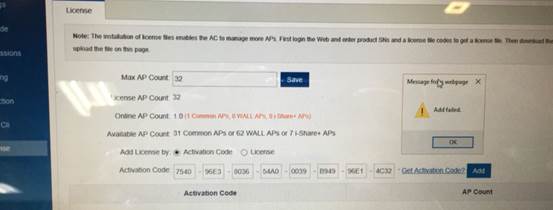
Solution:
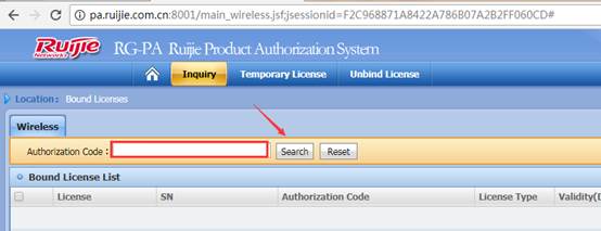
1. Confirm whether the SN is correct via the official website.

After login successfully, input authorization code, and then click “search” to check whether the relative device SN is consistent with the practical SN.
1. If the root case is the incorrect SN, unbind the License first
Step1:
Visit official website (http://www.ruijienetworks.com/service/License.aspx ), unbind License files.
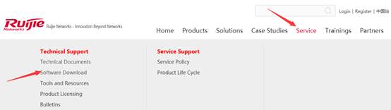
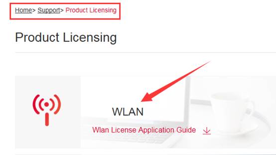
Click "Service" ->”Support” ->"Product Licensing" ->choose "WLAN" for wireless license unbinding. Choose “Unbind License”-> choose “Wireless”-> click “Unbind License”, then click ”Complete” after filling in product info.
Note: Before unbinding the license files, you should register first if you do not have an account for login.
Then in the pop-up dialog box, click “finish” to submit an application.
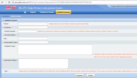
Step2: After completing the application, submitted it to TAC for application via e-mail account: service_rj@ruijienetworks.com. And then waiting for approval.
Click "Service" ->”Support” ->"Product Licensing" ->choose "WLAN" for wireless license unbinding. Choose “Unbind License”-> choose “Wireless”-> Check the approval status, if approved, customer can apply for a new license with the original S/N.
Warm prompt:
After unbind the license successfully, if you have the requirement of Wireless License Registration, please follow the following steps to apply for new license.
Step1: Obtain the license register number.
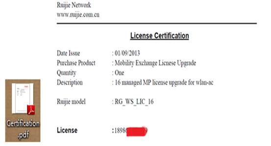
Open the attachment in the Authorization Letter to obtain the Authentication Code..

Or obtain the authentication code from the CD. There is a pdf file in the CD which is shown as follow:
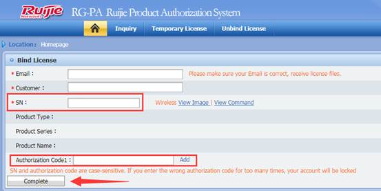
Step2: Visit the official website, bind License files.
Click "Service" ->”Support” ->"Product Licensing" ->choose "WLAN" for wireless license binding, after filling in the information, click “Complete”, it will jump to the download page of. lic file.
Step3: Install the authorization document
Note: If the license obtained by user is a. lic file, install the license with the following way
i) Upload the local license file to the wlc.
Configuration Example:
Ruijie#copy tftp://192.168.64.2/LIC-WLAN-AP-800000015692434.lic flash:/LIC-WLAN-AP- 800000015692434.lic
Press Ctrl+C to quit
!
Copy success.
ii) Install license file
Configuration Example:
Ruijie# license install flash:LIC-WLAN-AP-800000015692434.lic
Are you sure to install this license[y/n]:y
Success to install license file, service name: LIC-WLAN-AP-8.
Step3: Install the authorization document
Note: If the license obtained by user is a license key, install the license with the following way
i) The following shows the similar format of the license obtained by the user
XXXX-XXXX-XXXX-XXXX-XXXX-XXXX-XXXX-XXXX
Record the generated license key, connect to the wlan-ac device, and use the set license license command. If it prompts it is correct, the register application is successful. If it prompts the error, contact the Ruijie Customer Service center for the related consultation.
ii) Configure the License Basic Features
Configuration Example:
Ruijie# configure terminal
Enter configuration commands, one per line. End with CNTL/Z.
Ruijie(config)# set license AAAA-BBBB-CCCC-DDDD-EEEE-FFFF-GGGG-HHHH
Verification
Showing the License Configuration, you could find you have add new license successfully.
Ruijie# show license
1.7 FAQ
1.7.1 what traffic is need to be allowed to pass the firewall between the AC and the RADIUS server?
Interaction between the AC and the RADIUS server is generally based on the RADIUS protocol and SNMP. The ports to be opened are:
RADIUS port: Based on UDP. The default authentication port is 1812 and the default accounting port is 1813, which are both on the RADIUS server.
SNMP port: Based on UDP. The port is 161, which is on the AC.
1.7.2 How to kick a user offline
Check the user's MAC address:
WS#show ac-con client by-ap-name
Total Sta Num : 4
Cnt STA MACAP NAMEWlan Id Radio Id Vlan Id Valid
------ --------------- -------------------- --------- --------- --------- ---------
1.6a99.6c5aBF2_AP_031122091
2701a.04a9.a1b2BF2_AP_062123091
3 0026.c690.0a06 BF7_AP_011122091
4001f.3b3b.b435BF7_AP_011122091
Kick the user offline:
WS(config)#ac-controller
WS(config-ac)#client-kick H.H.H----->H.H.H is the user's MAC address.
Because the client will be automatically reconnected, when the show ac-con client by-ap-name command is run after the user is forced offline, the offline STA is still displayed.
1.7.3 Where is the ap-config file saved on the AC?
It’s saved in the ap-config.text file in AC flash.
1.7.4 Does the wireless network support VLAN-Group?
A VLAN-Group contains multiple VLANs. By associating with a VLAN-Group, a WLAN can map to multiple VLANs and VLANs can be flexibly allocated to STAs connected to the WLAN. The VLANs are allocated mainly in the following two modes:
After the STA passes the 802.1x authentication, the authentication server assigns a VLAN for the STA. The STA must be deployed in the 802.1x authentication mode and the authentication mode must be supported by the authentication server.
The server assigns the VLAN for the STA according to the idle status of the address pool.
1.7.5 How to view the wireless terminal type and operating system information on the AC?
Enable ip dhcp snooping and run the following command on AC:
ruijie#sh terminal-identify user
User entry list: 3
mac-address aging-time terminal-type
-----------------------------------------
68df.ddc7.de5a --:-- XIAOMI Phone Android 4.2
3859.f98b.658b --:-- PC Windows 7
a844.8130.c304 --:-- Nokia Phone Windows 8
Note: Due to terminal restrictions, the terminal may not be identified completely correct. When the terminal is connected to the wireless network, a DHCP packet is sent. The device reads the option 60 field in the packet. The field carries the terminal type information. However, not the DHCP packet of all the terminals carries the field, and thus the read success rate is not 100%.
1.7.6 Which of “ap-conf all” and “ap-config name” takes effect first?
The AP configuration under ap-config name takes effect first. If the AP under ap-config name is not configured, the ap-config all configuration takes effect.
1.7.7 How to fix when the device cannot ping the domain name?
Supplement the configuration AC(config)#ip name-server 8.8.8.8, which is used to set the DNS domain name for the device. You can modify the configuration based on the actual environment. Ensure that the AC normally communicates with the extranet.
1.7.8 How to delete an offline AP?
Perform the following operation:
Ruijie(config)#no ap-config ap-name1
Ruijie(config)#no ap-config all ----Delete the ap-config of all the offline APs.
Only configurations of offline APs can be deleted.
1.7.9 How to configure the location of a fit AP?
Refer to the following configuration:
Ruijie(config)#ap-config 001a.a9bf.ffdc
Ruijie(config-ap)#location meeting room
1.7.10 How to modify the address used by the AC to create the CAPWAP tunnel?
Ruijie(config)#ac-controller
Ruijie(config-ac)#capwap ctrl-ip 2.2.2.2
1.7.11 How to modify the SSID of the wireless network?
Go to the WLAN configuration mode:
Ruijie(config)#wlan-config 1 ( “1” is the wlan sequence)
Ruijie(config-wlan)#ssid yy (yy is the new SSID)
1.7.12 How to configure the static AP IP address in fit AP mode?
Refer to the command: (when this parameter is modified, a tunnel is re-created.)
(1) Log on to the AP through the Console or Telnet port, and enter the global mode (the password is apdebug) to configure the static AP IP address, default route, and AC IP address:
Ruijie(config)#acip ipv4 1.1.1.1 // Configure the IP address for the AC.
Ruijie(config)#apip ipv4 172.16.1.34 255.255.255.0 172.16.1.109
(2) After the tunnel between the AP and the AC is created, log on to the AC to configure a static IP address for the AP:
Ruijie(config)#ap-config 220e
Ruijie(config-ap)#acip ipv4 1.1.1.1 ---->Configure the IP address of the AC.
Ruijie(config-ap)#ip address 172.16.1.34 255.255.255.0 172.16.1.109 ---->Configure the IP address, mask, and gateway for the AP. After configuration, the capwap tunnel will be re-created.
The configurations retain even the AP is restarted.
1.7.13 How to disable a radio of the AP?
In fat mode, directly go to this radio and shut it down.
Ruijie(config)#interface dot11radio 1/0
Ruijie(config-if-dot11radio 1/0)#shutdown
In fit mode:
Ruijie(config)#ap-config ap-name ---->Go to the AP configuration mode
Ruijie(config-ap)#no enable-radio 1 ---->Disable the radio 1.
1.7.14 How to disable automatic adjustment for the RRM channel?
Ruijie(config)#advanced 802.11a channel global off
Ruijie(config)#advanced 802.11b channel global off
1.7.15 How to cancel AAA authentication for AC logon when AAA authentication is enabled on the AC?
You can cancel AAA authentication for AC logon by modifying the configurations.
Ruijie(config)#aaa new-model
Ruijie(config)#aaa authentication login no-login none ---->Create an AAA logon authentication list named "no-login" and set the configuration to none (no authentication).
Ruijie(config)#line con 0
Ruijie(config-line)#login authentication no-login ---->Apply the no-login to the console line, which indicates that the AAA authentication is not used.
Ruijie(config-line)#line vty 0 35
Ruijie(config-line)#login authentication no-login ---->No password is needed for logon through the Telnet port.
1.7.16 How to configure switchover of the AC/AP O/E multiplexing interface
1. On AP:
Ruijie(config)#interface gigabitEthernet0/1
Ruijie(config-if-GigabitEthernet 0/1)# media-type baset ---->Enable the electrical interface.
Ruijie(config-if-GigabitEthernet 0/1)#media-type basex ---->Enable the optical interface.
1. On AC:
Ruijie(config)#interface gigabitEthernet 0/1
Ruijie(config-if-GigabitEthernet 0/1)#medium-type copper
Ruijie(config-if-GigabitEthernet 0/1)#medium-type fiber
Ruijie(config-if-GigabitEthernet 0/1)#end
Ruijie#write
1.7.17 How to synchronize the AC time to the AP
Ruijie(config)# ap-config AP0001 //Enter the specified AP configuration mode.
Ruijie(config-ap)# timestamp /Configure AP0001 to synchronize the time of the local AC to the AP.
1.7.18 How to configure daily timed restart for the AP?
To prevent that the network connection is affected by too large load caused by long-time running of the AP, the daily timed restart can be set for the AP to ensure the network connection quality.
Configure Ruijie-AP1 to restart the AP at 1:00:00 each day on AC:
Ruijie(config)#ap-config Ruijie-AP1
Ruijie(config-ap)#reload at 1:00:00
1.7.19 How to close the LED indicator of the AP?
(1) Define a schedule session.
AC(config)#schedule session 1
AC(config)#schedule session 1 time-range 1 period Sun to Sat time 00:00 to 23:59
(2) Apply the schedule session on the AP
AC(config)#ap-config ap-name
AC(config-ap)#quiet-mode session 1
1.7.20 How to check the number of APs that can be supported by a device?
ruijie#sh ac-config
AC Configuration info:
max_wtp:32
sta_limit:1024
license wtp max:32
license sta max:1024
serial auth :Disable
password auth :Disable
certificate auth :Disable
Bind AP MAC :Disable
AP Priority :Disable
supp_psk_cer :Disable
ac_name:end
ac location :Ruijie_COM
1.7.21 How to view the MAC address of the AC?
WS6108#sh ac-config
AC State info:
sta_num :0
act_wtp :6
localIpAddr :1.1.1.1
localIpAddr6 :::
used wtp :6.0(6 normal 0 half 0 zero)
remain wtp :42 normal 84 half 634 zero
HW Ver :1.01
SW Ver :AC_RGOS 11.1(5)B7, Release(02231014)
Mac address :5869.6c20.726a
Product ID :WS6108
NET ID :9876543210012345
NAS ID :5869.6c20.726a
For VAC:
WS6108#show member
System description : WS6108
System Mac Address : 58:69:6C:20:72:6A
1.7.22 How to fix when the AP management address is forgotten?
The administrator forgets the management address of WALL-AP but does not want to modify the device configurations or the factory settings of the device cannot be restored. This method is also applicable for devices with a Console port but cannot be logged onto through the Console port.
1. Configuration Tips
1. Execute the packet capture software on a PC to capture packets from the interface of the wired network.
1. Connect the WALL-AP cable to the PC and power on the AP.
1. Configuration Steps
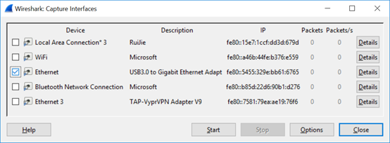
1. Execute the packet capture software (using Wireshark for an example) to capture packets from the wired interface.
(1) Select the interface.
(2) Select the wired interface of the AP and click Start to capture the packets.
(3) Connect the wired interface of the PC to the AP Ethernet port that is not powered on.
(4) Power on the AP to view packets output by the packet capture software on the PC. Pay attention to the ARP packets.
Because the PC is directly connected to the AP, all the ARP packets except those sent by the PC are ARP packets sent by the AP.
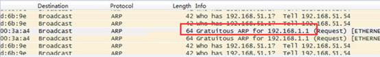
(5) After getting the AP IP address from the ARP packets, try to log on to the AP through the Telnet port.
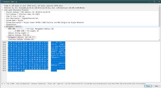
(6) The AP may not send the ARP resolution packets. In this case, you can use the LLDP packets to obtain the AP management address. The Management Address in the LLDP packets is the management address of the AP.
(7) If you still cannot log on to the AP, restore the factory settings of WALL-AP, which results in loss of all configurations. You can try to log on to APs with the Console port from a serial port.
It is found that during actual packet capture, the AP often does not send the ARP resolution packets. In this case, you can use the LLDP packets to obtain the AP management address.
1. The following is a packet capture screenshot:
1. Click to open the LLDP packet. The part in the red frame below is the management address of the AP:
1.7.23 How to fix when the system can output information but cannot be operated during CRT-based logon through the Console port?
1. Symptom
According to the AP320-I users, in case of logon through the Console port, there is information prompted, but no response is returned after Enter is pressed. Besides, no command can be entered.
1. Network Environment
The AP is new and just installed. It is logged onto through CRT.
1. Troubleshooting Steps
(1) Check whether the CRT or the HyperTerminal is used. If CRT is used, uncheck CTS/RTS.
(2) If an additional cable is used, confirm whether the driver is installed correctly.
(3) Change the baud rate. The baud rate for the version 1T8 is 115200 bps.
(4) Change the console cable and the PC.
1. Solution
Uncheck CTS/RTS.
1. Summary and Precautions
Summary: Other faults caused by the CRT traffic control function.
(1) You cannot use CRT to log on to the console.
(2) After CRT-based logon, the operation window is blank, the system outputs no information but the cursor flashes. The system has no response after you press Enter.
(3) After CRT-based logon, the operation window is blank, the system outputs no information but the cursor flashes. After you press Enter, the cursor moves but the system still outputs no information.
(4) After CRT-based logon, the system outputs information, but has no response after your press Enter and does not allow you to perform any operation.
(5) After HyperTerminal-based logon, the Data Traffic Control in COM attribute settings must be set to None.
1.7.24 How many APs can different AC Model manage?
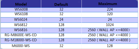
A WALL-AP occupies only 0.5 license. "<=4000" means up to4,000 WALL-APs are supported.
Run the show ac-c command in AC to display license occupation information. The meaning of four, normal, half, and zero is described below.
four: The AP occupies four licenses. Currently, only APs of the model AM5528 and AM5528(ES) occupy four licenses each. APs of the model AM5514 only occupy two licenses each.
normal: An ordinary AP occupies only one license, including AP220-E, AP320-I, and AP520.
half: A WALL-AP occupies only 0.5 license.
zero: The AP occupies no license. The AP is AP(MAP552(SR)) and APD-M.
1.7.25 How to view the number of licenses occupied by different AP model on AC?
AC#show ap-config product
Product ID Hardware Version Count Used Wtp
-------------------- ---------------- -------- --------
AM5528 1.00 245 980.0
AP520 1.00 906 906.0
AP630(IDA) 1.50 33 33.0
AP630(IODA) 1.00 83 83.0
1.7.26 How to migrate a wireless AC license to another device (unbinding license)
(1) Upgrade the device version to RGOS 11.1(5)B9 or a later version.
For authentication code:
Run the AC(config)#no set license activation-key command to unbind the authorized code. (The activation-key is a 32-bit activation code.)
For authentication file:
Run the AC#license unbind authorized file name command to unbind the authorized file to get the verification code.
You can run the show license unbind-code or show apmg debug unbind command to display the verification code.
Note: after activation code of the unbound license is deleted, the license cannot be installed on the device again.
(2) Submit the device serial number, the license activation code, and verification code on Ruijie authentication system(http://pa.ruijie.com.cn:8001/main_wireless.jsf) to unbind the license on the authorization system. Contact Ruijie TAC to approve the unbinding.
(3) To bind the license again, submit the serial number of the new device and authorization code to register the license. A new activation code is obtained.
(4) Install the new activation code to the new AC.
For More details, please refer to WLAN License Activation Guide:
1.7.27 Can multiple temporary licenses be imported to the same device?
You can apply for a temporary license for an AC three times. The application is automatically reviewed and approved. Only one temporary license of the same specifications can be imported into an AC. The second license overwrites the first. Multiple temporary licenses of different specifications can coexist in one AC. For example, when two temporary licenses can manage 32 APs are applied for the same AC, only one license can be imported to the AC. When a license can manage 32 APs and a license can management 128 APs are applied for the same AC, both licenses can be imported to the AC.
1.7.28 How to bind a license on VAC
(1) When VAC deployment is not finished yet, the procedure is same to that of normal AC
(2) When VAC deployment is finished, the procedure is basically the same. Bind the corresponding license authorization code to the device according to its serial number.
For authentication code, use set license command to bind the authentication code on main AC.
For authentication files, all the authorization files must be imported to the main AC and operated by running the following commands.
AC#license auto-install flash: LIC-WLAN-AP-51200000001765223.lic
The authorization files can be automatically uploaded.
If the authorization file is operated on the standby AC, the message "% Can’t execute this command in redundancy slave" is prompted.
(3) AC#license install means that the authorization file is only installed in this host.
1.7.29 Will APs go offline immediately if the license is unblind from AC?
No. The AP will not go offline unless it goes offline actively or the AC is restarted. As long as the current AP does not actively go offline and the AC is not restarted, the AP will always be online.
1.7.30 Will online Aps be kicked offline when the licenses are insufficient after temporary authorization expires?
No. APs will not be kicked offline due to deletion of temporary or formal authorization. The system judges whether the licenses are sufficient only when the AP is getting online. APs that go offline after authorization expire cannot go online again.
Basic Features
2.1 Fit AP Configuration
2.1.1 CAPWAP
Summarize
With the development of wireless LAN, WLAN technology has been widely used in various fields such as family, enterprise and public places etc. The transmission of wireless frame between access point and wireless terminations in the form of electromagnetic wave instead of wired medium, which makes the wireless terminals movable freely. WLAN technology is the integration of Ethernet and wireless technology and makes wireless terminals easy to access to the wireless local area network. Access point is the middle-transfer-device between wireless terminals and Access Controller in WLAN. When there are plenty of access points in WLAN, how to manage these Aps is key problem in operation.
FAT AP Architecture
In the traditional network architecture, the WTPs completely implement and terminate the 802.11 function so that frames on the wired LAN are 802.3 frames. Each WTP can be independently managed as a separate network entity on the network. The access point in such a network is often called a “Fat AP”.
FIT AP Architecture
The thin AP architecture is a hierarchical architecture that involves a WLAN controller that is responsible for configuration, control, and management of several WTPs. The WLAN controller is also known as the Access Controller (AC). The 802.11 function is split between the WTP and the AC. Because the WTPs in this model have a reduced function as compared to the fat AP architecture, they are called “Fit APs.”
Fit AP Architecture Advantages
Centralized management
Automatic software upgrade
High security and low interference
Since the distinct advantages of fit AP architecture, it’s generally adopted especially in large networks with many APs. The CAPWAP framework is used to define the interface and protocol between an AC and its controlled APs.
Currently, each manufacturer adopts their own private tunnel protocols to exchange messages between AC and AP and this leads to the problem that the AC and AP from different manufacturers cannot communicate with each other.
To solve this problem, IETFCAPWAP working group is set up in 2005 to standardize the tunnel protocols between AC and AP (RFC5415).
2 Terms Explanation
CAPWAP Control and Provisioning of Wireless Access Points
Local MAC Local Medium Access Control
Split MAC Split Medium Access Control
DTLS Datagram Transport Layer Security
WTP Wireless Terminal Point
AC Access Control
AP Access Point
3 CAPWAP Overview
CAPWAP (Control and Provisioning of Wireless Access Points) is a generic protocol that enables a controller to manage a collection of Wireless Terminal Point (WTP). The CAPWAP protocol is described in RFC 5415 which does not include specific wireless technologies; instead, it relies on a binding specification to extend the technology to a particular wireless technology. The binding specifications for the IEEE 802.11 wireless protocol are defined in RFC5416.
CAPWAP is an application layer protocol over UDP. It uses the Datagram Transport Layer Security (DTLS) encryption mechanism which is standard IETF protocol based on TLS.
CAPWAP Main Functions
To centralize the authentication and policy enforcement functions for a wireless network. The AC may also provide centralized bridging, forwarding and encryption of user traffic.
To enable shifting of the higher-level protocol processing from the WTP. This leaves the time-critical applications of wireless control and access in the WTPs, which are subject to severe cost pressure.
To provide an extensible protocol that is not bound to a specific wireless technology.
The CAPWAP tunnel is divided into:
Control tunnel: to transport the CAPWAP control messages
Data tunnel: to transport the CAPWAP data messages
See the figure below for CAPWAP tunnel:
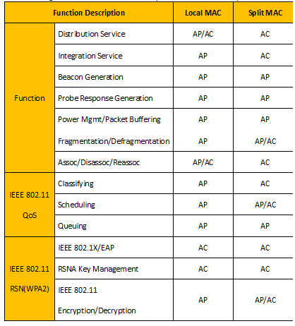
2.1 Local MAC and Split MAC
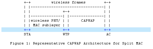
In the split MAC mode, all the layer 2 wireless data and management frames will be encapsulated by CAPWAP protocol and exchanged between AC and WTP.
As shown in figure 1, the wireless frames received from the station will be directly encapsulated and forwarded to AC.
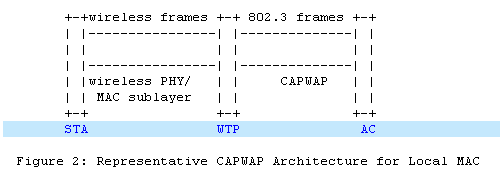
In the local MAC mode, the data frames can be forwarded through local bridge or 802.3 frames as shown in figure 2. In this mode, layer 2 management frames is encapsulated to802.3 frames on WTP and then forwarded to AC.
The functionassignment of Local MAC and Split MAC in CAPWAP protocol is listed in the table below:
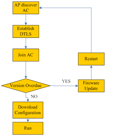
2.2 CAPWAP Working Process
Once one WTP is connected to the network, it will enter the state of AC discovery. WTP sends “discovery request” by means of broadcast, multicast or unicast. When unicast is used, WTP needs to obtain the IP address table of AC through DHCP or DNS. The ACs that receive “discovery request” will send “discovery response” to WTP.WTP will then select one among all responding ACs to establish DTLS connection. After DTLS is established successfully, WTP will send “john request” and AC will reply “john response” to confirm. If the firmware’s version on the WTP is overdue, the firmware update process is started and the WTP will download the latest firmware from AC. After firmware updating successfully, the WTP will restart and enter the discovery process again. If the firmware is the latest, the WTP will download the configuration parameters from AC and then enter the “run” process.
The whole process is illustrated in the figure below:
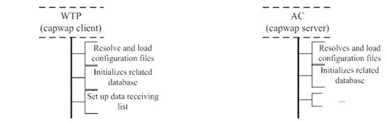
2.3 CAPWAP Session Establishment Process
The ladder diagram below illustrates the CAPWAP session establishment and message exchanges process between a WTP and AC.
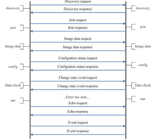
2. WTP sends “discovery request” by means of broadcast, multicast or unicast to discover the available ACs in the network.
2. After receiving the “discovery request” from WTP, AC responds a “Discovery Response” message to WTP to tell the supported service.
2. When the DTLS connection is established, WTP sends the “Join Request” to the AC to request service.
2. AC responds “Join Response” message to inform the WTP that AC can provide service to it.
2. WTP sends “Image data request” message to AC.
2. AC responds “Image data response” message to WTP and WTP can download firmware from AC.
2. WTP sends the current configuration information in “Configuration Status Request” message to AC.
2. AC provides the configuration parameters by responding “Configuration Status Response” message to WTP and WTP request configuration is covered.
2. WTP informs AC that WTP radio state is changed by sending “Change State Event Request” message to AC.
2. AC responds “Change State Event Response” message to WTP.
2. WTP sends “Echo Request” to keep the connection alive when other messages are not exchanged.
2. AC responds “Echo Response” to WTP.
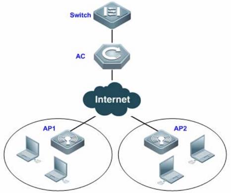
2.4 FIT AP Network Topology
In this topology, SKG1000 (AC) is responsible to manage a number of ACs and the communication between AC and AP is realized through CAPWAP tunnels.
As a powerful and high performance AC developed by SKSpurce, SKG1000 can support up to 20000APs and 220K users.
2.1.2 Basic Configuration
Scenario
With fit APs, a network consists of a wired switch, access controllers (ACs) and fit APs. APs are simple wireless access points without management and control functions. The AC manages all APs and sends control policies, which are not configured on each AP, to specified APs, as shown in the following figure. The AC is connected with multiple APs via the wired network, and users only need to configure and manage associated APs with the AC.
I. Requirements
a. AC distribute the configuration to all APs, and manage all Aps
b. All APs emit radio signals and connect STA
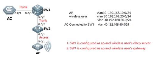
II. Network Topology
III. Configuration Tips
1) Make sure that AC and AP's firmware should be consistent, using command in CLI "Ruijie>show version"
2) Make sure AP is working on fit mode, using command in CLI "Ruijie>show ap-mode " to check. If it shows fat mode, please modify as follow step:
Ruijie>enable ------>enter the previlege mode
Ruijie#configure terminal ------>enter the config mode
Ruijie(config)#ap-mode fit ------>modify to fit-mode
Ruijie(config)#end ------>exit the config mode
Ruijie#write ------>save the config
IV. Configuration Steps
1) Configure AC
Step1: config Vlan, include user vlan and interconnect vlan,
Ruijie>enable
Ruijie#configure terminal
Ruijie(config)#vlan 20 ------>user vlan
Ruijie(config-vlan)#name sta
Ruijie(config-vlan)#exit
Ruijie(config)#vlan 30 ------>user vlan
Ruijie(config-vlan)#name sta
Ruijie(config-vlan)#exit
Ruijie(config)#vlan 40 ------>interconnect vlan for ac and sw1
Ruijie(config-vlan)#exit
Ruijie(config)#interface vlan 20 ------>user interface vlan(must config)
Ruijie(config-int-vlan)#ip add 192.168.20.2 255.255.255.0 ----->(optional config), in this case, user gateway is configured on sw1, so ip address for this
interface can be configured or not.
Ruijie(config)#interface vlan 30 ------>user interface vlan(must config)
Ruijie(config-int-vlan)#ip add 192.168.30.2 255.255.255.0 ----->(optional config), in this case, user gateway is configured on sw1, so ip address for this
interface can be configured or not.
Ruijie(config-int-vlan)#exit
Step2:Config ssid (multi ssid)
Ruijie(config)#wlan-config 1 Ruijie1
Ruijie(config-wlan)#enable-broad-ssid ------->enable broadcast ssid
Ruijie(config-wlan)#exit
Ruijie(config)#wlan-config 2 Ruijie2
Ruijie(config-wlan)#enable-broad-ssid ------->enable broadcast ssid
Ruijie(config-wlan)#exit
Step3:Config ag-group
Ruijie(config)#ap-group default
Ruijie(config-ap-group)#interface-mapping 1 20 ------->associate wlan-config 1 with user vlan 30
Ruijie(config-ap-group)#interface-mapping 2 30 ------->associate wlan-config 2 with user vlan 30
Ruijie(config-ap-group)#exit
Note:If config ag-goup default, then all AP will asscociate to " ap-group default" group
Step4:Config svi and routing
Ruijie(config)#ip route 0.0.0.0 0.0.0.0 192.168.40.1 ------->default routing to sw1
Ruijie(config)#interface vlan 40 ------->interconnect vlan with sw1
Ruijie(config-int-vlan)#ip address 192.168.40.2 255.255.255.0
Ruijie(config-int-vlan)#exit
Ruijie(config)#interface loopback 0
Ruijie(config-int-loopback)#ip address 1.1.1.1 255.255.255.0 ------->AC initialize CAPWAP tunnel setup from loopback 0 interface
Ruijie(config-int-loopback)#exit
Ruijie(config)#interface GigabitEthernet 0/1
Ruijie(config-int-GigabitEthernet 0/1)#switchport mode trunk ------->connect to sw1, trunk port, allow user vlan、AP vlan、AC-to-SW1 vlan
Step5:Save config
Ruijie(config-int-GigabitEthernet 0/1)#end
Ruijie#write
2) Configure core switch(SW1)
Step1:Vlan config, config user vlan, ap vlan and interconnect vlan
Ruijie>enable
Ruijie#configure terminal
Ruijie(config)#vlan 10 ------>ap vlan
Ruijie(config-vlan)#exit
Ruijie(config)#vlan 20 ------>user vlan
Ruijie(config-vlan)#exit
Ruijie(config)#vlan 30 ------>user vlan
Ruijie(config-vlan)#exit
Ruijie(config)#vlan 40 ------>interconnect vlan with AC
Ruijie(config-vlan)#exit
Step2:Config interface and svi
Ruijie(config)# interface GigabitEthernet 0/1
Ruijie(config-int-GigabitEthernet 0/1)#switchport mode trunk ------->uplink port, connect to AC, trunk port,allow user vlan、AP vlan、AC-to-SW1 vlan
Ruijie(config-int-GigabitEthernet 0/1)#exit
Ruijie(config)#interface GigabitEthernet 0/2
Ruijie(config-int-GigabitEthernet 0/2)#switchport mode trunk ------->downlink port, connect to SW2,trunk port,allow user vlan、AP vlan
Ruijie(config-int-GigabitEthernet 0/2)#exit
Ruijie(config)#interface vlan 10 ------>ap gateway
Ruijie(config-int-vlan)#ip address 192.168.10.1 255.255.255.0
Ruijie(config-int-vlan)#interface vlan 20 ------->sta gateway
Ruijie(config-int-vlan)#ip address 192.168.20.1 255.255.255.0
Ruijie(config-int-vlan)#interface vlan 30 ------->sta gateway
Ruijie(config-int-vlan)#ip address 192.168.30.1 255.255.255.0
Ruijie(config-int-vlan)#interface vlan 40 ------->interconnect with ac
Ruijie(config-int-vlan)#ip address 192.168.40.1 255.255.255.0
Ruijie(config-int-vlan)#exit
Step3:Conifg ip dhcp server
Ruijie(config)#service dhcp
Ruijie(config)#ip dhcp pool ap_ruijie ------->create dhcp pool for ap,pool name is ap_ruijie
Ruijie(config-dhcp)#option 138 ip 1.1.1.1 ------->config option 138, assign ac loopaback 0 ip address
Ruijie(config-dhcp)#network 192.168.10.0 255.255.255.0 ------->assign these address to ap
Ruijie(config-dhcp)#default-route 192.168.10.1 ------->assign the gateway to ap
Ruijie(config-dhcp)#exit
Ruijie(config)#ip dhcp pool user_ruijie1 ------->create dhcp pool for sta,pool name is user_ruijie
Ruijie(config-dhcp)#network 192.168.20.0 255.255.255.0 ------->assign these address to sta
Ruijie(config-dhcp)#default-route 192.168.20.1 ------->assign the gateway to sta
Ruijie(config-dhcp)#dns-server 8.8.8.8 ------->assign the dns to sta
Ruijie(config-dhcp)#exit
Ruijie(config)#ip dhcp pool user_ruijie2 ------->create dhcp pool for sta,pool name is user_ruijie
Ruijie(config-dhcp)#network 192.168.30.0 255.255.255.0 ------->assign these address to sta
Ruijie(config-dhcp)#default-route 192.168.30.1 ------->assign the gateway to sta
Ruijie(config-dhcp)#dns-server 8.8.8.8 ------->assign the dns to sta
Ruijie(config-dhcp)#exit
//Note: when there is no dhcp pool for AP, You could also excute command to assign acip and apip for ap. configuration example is as follow:
Ruijie(config)#acip ipv4 x.x.x.x
Ruijie(config)#apip ipv4 x.x.x.x
Step4:Config static routing
Ruijie(config)#ip route 1.1.1.1 255.255.255.255 192.168.40.2 ------->config static route, route to AC loopback0
Step5:Save configuration
Ruijie(config)#exit
Ruijie#write
3) Configure access switch (SW2)
Step1:Config vlan, create ap vlan
Ruijie>enable
Ruijie#configure terminal
Ruijie(config)#vlan 10
Ruijie(config-vlan)#exit
Step2:Config interface
Ruijie(config)#interface GigabitEthernet 0/1
Ruijie(config-int-GigabitEthernet 0/1)#switchport access vlan 10 ------->connect to AC, access port, allow ap vlan
Ruijie(config-int-GigabitEthernet 0/1)#exit
Ruijie(config)#interface GigabitEthernet 0/2
Ruijie(config-int-GigabitEthernet 0/2)#switchport mode trunk ------->connect to SW1, trunk port
Step3:Save configuration
Ruijie(config-int-GigabitEthernet 0/2)#end
Ruijie#write
V. Verification
1) STA connect to the ssid
2) Check ap config on AC
Ruijie#show ap-config summary
========= show ap status =========
Radio: E = enabled, D = disabled, N = Not exist
Current Sta number
Channel: * = Global
Power Level = Percent
Online AP number: 1
Offline AP number: 0
AP Name IP Address Mac Address Radio 1 Radio 2 Up/Off time State
---------------------------------------- --------------- -------------- ------------------- ------------------- ------------- -----
1414.4b13.c248 192.168.10.2 1414.4b13.c248 E 1 6* 100 E 0 153* 100 0:09:04:28 Run
3) Check sta information on AC
Ruijie#show ac-config client by-ap-name
========= show sta status =========
AP : ap name/radio id
Status: Speed/Power Save/Work Mode, E = enable power save, D = disable power save
Total Sta Num: 1
STA MAC IPV4 Address AP Wlan Vlan Status Asso Auth Net Auth Up time
-------------- --------------- ---------------------------------------- ---- ---- -------------- --------- --------- -------------
2.27b0.169f 192.168.20.2 1414.4b13.c248/1 1 20 58.0M/D/bn WPA2_PSK 0:00:11:21
8ca9.829a.b1ea 192.168.30.2 1414.4b13.c248/1 2 30 58.0M/D/bn WPA2_PSK 0:03:22:31
What if it don’t work?
Use the following steps while aps cannot go online:
1) Confirm whether the versions of AC and AP are consistent, if not, recommend to upgrade first, the latest firmware could be download from our official website: http://www.ruijienetworks.com/service/download.aspx
2) Confirm whether the AP obtain ip address and ACIP successfully or not with command below:
AP# Show ip int br
AP#show capwap client sta
3) Confirm the connectivity between AP and ACIP, if disconnected, check the ip routes on AP:
AP# show ip route
If there is not ip route pointing to ACIP, add an ip route,examples are as follows
AP(config)# ip route 1.1.1.1 255.255.255.0 192.168.1.2
4) Confirm whether the license is not enough.
Examples are as follows:
WS5302#sh ac-config
AC Configuration info:
max_wtp :32 // configure wtp limit on ac-con mode to limit the AP number.
sta_limit :1024
license wtp max :32 //ap numbers can be supported on ac.
license sta max :1024
serial auth :Disable
password auth :Disable
certificate auth:Disable
supp_psk_cer :Disable
r_mac :Enable
da_dtls :Disable
ac_name :Ac_001aa917151c
udp_lite :UDP
ECN_Sup :Disable
mtu :1500
ap_sw_ver :
ac location :Ac_COM
ac_ipv4_num :0
ac_namewp_num :0
AC State info:
sta_num :0
act_wtp :1
WS5302#show license //check the license
Serial Number : 9071FH4280024
No. Activation Key AP Number
-------------------------------------------------------
-------------------------------------------------------
Total 32 access points are supported.
WS5302#show ap-config summary
========= show ap status =========
Radio: E = enabled, D = disabled, N = Not exist
Current Sta number
Channel: * = Global
Power Level = Percent
Online AP number: 1 //online AP number
Offline AP number: 0
AP Name IP Address Mac Address Radio 1 Radio 2 Up/Off time State
---------------------------------------- --------------- -------------- ------------------- ------------------- ------------- -----
001a.a94e.d529 192.168.100.3 001a.a94e.d529 E 0 11* 100 E 0 157* 100 0:03:09:17 Run
5) If the AP still could not go online successfully after checking the infomation above, collect the info with the following command list and submit a case to our case portal http://case.ruijienetworks.com/login_page.php for further checking:
1) collect info on AC:
show version
show running
show ac-config
show license
show ap-config summary
show capwap sta
show cpu
show memory
show ip route
show ip interface brief
2)Collect info on AP:
show version
show ap-mode
show capwap sta
show ip route
show log
show ap-statistic aclist (confirm whether ap obtains option 138 address)
show capwap client state (11.x)
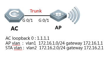
2.1.3 AC Directly Connect to AP
I. Requirements
1) AC connect to AP directly
2) This scene is usually used in the lab in usual.
II. Network Topology
III. Configuration Tips
1) Make sure that AC and AP's firmware should be consistent, using command in CLI "Ruijie>show version"
2) Make sure AP is working on fit mode, using command in CLI "Ruijie>show ap-mode " to check. If it shows fat mode, please modify as follow step:
Ruijie>enable ------>enter the previlege mode
Ruijie#configure terminal ------>enter the config mode
Ruijie(config)#ap-mode fit ------>modify to fit-mode
Ruijie(config)#end ------>exit the config mode
Ruijie#write ------>save the config
IV. Configuration Steps
Step1: config vlan, create user vlan and ap vlan
Ruijie>enable
Ruijie#configure terminal
Ruijie(config)#vlan 1
Ruijie(config-vlan)#exit
Ruijie(config)#vlan 2
Ruijie(config-vlan)#exit
Step2: config AP, STA gateway and loopback 0
Ruijie(config)#interface vlan 1 ------>ap gateway
Ruijie(config-int-vlan)#ip address 172.16.1.1 255.255.255.0
Ruijie(config-int-vlan)#exit
Ruijie(config)#interface vlan 2 ------>sta gateway
Ruijie(config-int-vlan)#ip address 172.16.2.1 255.255.255.0
Ruijie(config-int-vlan)#exit
Ruijie(config)#interface loopback 0
Ruijie(config-int-loopback)#ip address 1.1.1.1 255.255.255.0
Ruijie(config-int-loopback)#exit
Step3: config SSID
config Wlan-config
Ruijie(config)#wlan-config 1 Ruijie-test ------->config ssid named Ruijie-test
Ruijie(config-wlan)#enable-broad-ssid ------->enable brocast ssid
Ruijie(config-wlan)#exit
config ap-group
Ruijie(config)#ap-group default
Ruijie(config-ap-group)#interface-mapping 1 2 ------->associate with wlan-config 1 and vlan2
Ruijie(config-ap-group)#exit
Step4: config AC interface
Ruijie(config-int-loopback)#interface GigabitEthernet 0/1
Ruijie(config-int-GigabitEthernet 0/1)#switchport access vlan 1 ------->connect to ap, allow ap vlan
Step5: config ip dhcp server for AP
Ruijie(config)#service dhcp
Ruijie(config)#ip dhcp pool ap_ruijie ------->config dhcp pool, named ap_ruijie
Ruijie(config-dhcp)#option 138 ip 1.1.1.1
Ruijie(config-dhcp)#network 172.16.1.0 255.255.255.0 ------->assign the address to ap
Ruijie(config-dhcp)#default-route 172.16.1.1 ------->assign the gateway to ap
Ruijie(config-dhcp)#exit
Note: When there is no dhcp for AP, you could also excute command to assign acip and apip for ap. configuration example is as follow:
Ruijie(config)#acip ipv4 x.x.x.x
Ruijie(config)#apip ipv4 x.x.x.x
Step6: config ip dhcp server for STA
Ruijie(config)#ip dhcp pool user_ruijie ------->config dhcp pool, named user_ruijie
Ruijie(config-dhcp)#network 172.16.2.0 255.255.255.0 ------->assign the address to STA
Ruijie(config-dhcp)#default-route 172.16.2.1 ------->assign the gateway to STA
Ruijie(config-dhcp)#dns-server 8.8.8.8 ------->assign the dns to STA
Ruijie(config-dhcp)#exit
Step7: save configuration
Ruijie(config)#exit
Ruijie#write
V. Verification
1) STA connect to the ssid.
2) Check ap config on AC
Ruijie#show ap-config summary
========= show ap status =========
Radio: E = enabled, D = disabled, N = Not exist
Current Sta number
Channel: * = Global
Power Level = Percent
Online AP number: 1
Offline AP number: 0
AP Name IP Address Mac Address Radio 1 Radio 2 Up/Off time State
---------------------------------------- --------------- -------------- ------------------- ------------------- ------------- -----
1414.4b13.c248 172.16.1.2 1414.4b13.c248 E 1 6* 100 E 0 153* 100 0:06:03:00 Run
3) Check sta information on AC
Ruijie#show ac-config client by-ap-name
========= show sta status =========
AP : ap name/radio id
Status: Speed/Power Save/Work Mode, E = enable power save, D = disable power save
Total Sta Num: 1
STA MAC IPV4 Address AP Wlan Vlan Status Asso Auth Net Auth Up time
-------------- --------------- ---------------------------------------- ---- ---- -------------- --------- --------- -------------
2.27b0.169f 172.16.2.2 1414.4b13.c248/1 1 2 30 0.0M/D/bn WPA2_PSK 0:00:01:01
Note: Recommand upgrade the AP&AC to the latest and more stable version, to avoid the compatibility issues
2.1.4 Wall AP Front Port VLAN Assignment
I. Requirements
Assign the front ports of AP110-W & AP120-W to different vlan
II. Network Topology
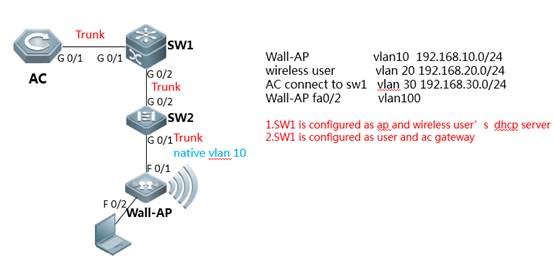
III. Configuration Tips
1) Make sure that AC and AP's firmware should be consistent, using command in CLI "Ruijie>show version"
2) Make sure AP is working on fit mode, using command in CLI "Ruijie>show ap-mode " to check. If it shows fat mode, please modify as follow step:
Ruijie>enable ------>enter the previlege mode
Ruijie#configure terminal ------>enter the config mode
Ruijie(config)#ap-mode fit ------>modify to fit-mode
Ruijie(config)#end ------>exit the config mode
Ruijie#write ------>save the config
Note: If the version of AP is earlier than B8, you should execute command “no bridge-l2-isolation” on global mode in case the PC can not access to the network
Ruijie(config)#no bridge-l2-isolation
IV. Configuration Steps
1) AC configuration
Step1: configuring Vlan, include user vlan and interconnect vlan,
Ruijie>enable
Ruijie#configure terminal
Ruijie(config)#vlan 20 ------>user vlan
Ruijie(config-vlan)#name sta
Ruijie(config-vlan)#exit
Ruijie(config)#vlan 30 ------>interconnect vlan for ac and sw1
Ruijie(config-vlan)#exit
Ruijie(config)#interface vlan 20 ------>user interface vlan(must config)
Ruijie(config-int-vlan)#ip add 192.168.20.2 255.255.255.0 ----->(optional config), in this case, user gateway is configured on sw1, so ip address for this interface can be configured or not.
Ruijie(config-int-vlan)#exit
Step2:Configuring ssid
Ruijie(config)#wlan-config 1 Ruijie
Ruijie(config-wlan)#enable-broad-ssid ------->enable broadcast ssid
Ruijie(config-wlan)#exit
Step3:Configuring ag-group
Ruijie(config)#ap-group b8fd.3200.3aa3 ------->enter ap-group with ap's mac-address
Ruijie(config-ap-group)#interface-mapping 1 20 ------->associate wlan-config id with vlan
Ruijie(config)#ap-config ap120-w
Ruijie(config-ap)#ap-group b8fd.3200.3aa3
Ruijie(config-ap)#wired-vlan 100 port 1 ------>assign fa0/2 to vlan 100
Ruijie(config-ap)#exit
Note:If config ag-goup default, then all AP will asscociate to "ap-group default" group
Step4: Configuring svi and routing
Ruijie(config)#ip route 0.0.0.0 0.0.0.0 192.168.30.1 ------->default routing to sw1
Ruijie(config)#interface vlan 30 ------->interconnect vlan with sw1
Ruijie(config-int-vlan)#ip address 192.168.30.2 255.255.255.0
Ruijie(config-int-vlan)#exit
Ruijie(config)#interface loopback 0
Ruijie(config-int-loopback)#ip address 1.1.1.1 255.255.255.0 ------->AC initialize CAPWAP tunnel setup from loopback 0 interface
Ruijie(config-int-loopback)#exit
Ruijie(config)#interface GigabitEthernet 0/1
Ruijie(config-int-GigabitEthernet 0/1)#switchport mode trunk ------->connect to sw1, trunk port, allow user vlan、AP vlan、AC-to-SW1 vlan
Step5:Save configurations
Ruijie(config-int-GigabitEthernet 0/1)#end
Ruijie#write
2) Config core switch (SW1)
Step1:Configuring user vlan,ap vlan and interconnect vlan
Ruijie>enable
Ruijie#configure terminal
Ruijie(config)#vlan 10 ------>ap vlan
Ruijie(config-vlan)#exit
Ruijie(config)#vlan 20 ------>user vlan
Ruijie(config-vlan)#exit
Ruijie(config)#vlan 30 ------>interconnect vlan with AC
Ruijie(config-vlan)#exit
Step2:Configuring interfaces and svi
Ruijie(config)# interface GigabitEthernet 0/1
Ruijie(config-int-GigabitEthernet 0/1)#switchport mode trunk ------->uplink port, connect to AC, trunk port,allow user vlan、AP vlan、AC-to-SW1 vlan
Ruijie(config-int-GigabitEthernet 0/1)#exit
Ruijie(config)#interface GigabitEthernet 0/2
Ruijie(config-int-GigabitEthernet 0/2)#switchport mode trunk ------->downlink port, connect to SW2,trunk port,allow user vlan、AP vlan
Ruijie(config-int-GigabitEthernet 0/2)#exit
Ruijie(config)#interface vlan 10 ------>ap gateway
Ruijie(config-int-vlan)#ip address 192.168.10.1 255.255.255.0
Ruijie(config-int-vlan)#interface vlan 20 ------->wireless user gateway
Ruijie(config-int-vlan)#ip address 192.168.20.1 255.255.255.0
Ruijie(config-int-vlan)#interface vlan 30 ------->interconnect with ac
Ruijie(config-int-vlan)#ip address 192.168.30.1 255.255.255.0
Ruijie(config-int-vlan)#interface vlan 100 ------->gateway for ap120-w front port fa0/2
Ruijie(config-int-vlan)#ip address 192.168.100.1 255.255.255.0
Ruijie(config-int-vlan)#exit
Step3:Conifguring ip dhcp server
Ruijie(config)#service dhcp
Ruijie(config)#ip dhcp pool ap_ruijie ------->create dhcp pool for ap,pool name is ap_ruijie
Ruijie(config-dhcp)#option 138 ip 1.1.1.1 ------->config option 138, assign ac loopaback 0 ip address
Ruijie(config-dhcp)#network 192.168.10.0 255.255.255.0 ------->assign these address to ap
Ruijie(config-dhcp)#default-route 192.168.10.1 ------->assign the gateway to ap
Ruijie(config-dhcp)#exit
Ruijie(config)#ip dhcp pool user_ruijie ------->create dhcp pool for sta,pool name is user_ruijie
Ruijie(config-dhcp)#network 192.168.20.0 255.255.255.0 ------->assign these address to sta
Ruijie(config-dhcp)#default-route 192.168.20.1 ------->assign the gateway to sta
Ruijie(config-dhcp)#dns-server 8.8.8.8 ------->assign the dns to sta
Ruijie(config-dhcp)#exit
Step4:Configuring static routing
Ruijie(config)#ip route 1.1.1.1 255.255.255.255 192.168.30.2 ------->config static route, route to AC loopback0
Step5:Save configuration
Ruijie(config)#exit
Ruijie#write
3) Configuring access switch (SW2)
Step1:Configuring vlan, create ap vlan
Ruijie>enable
Ruijie#configure terminal
Ruijie(config)#vlan 10
Ruijie(config-vlan)#exit
Step2:Configuring interface
Ruijie(config)#interface GigabitEthernet 0/1 ------->connect to AP120-W
Ruijie(config-int-GigabitEthernet 0/1)#switchport mode trunk
Ruijie(config-int-GigabitEthernet 0/1)#switchport trunk native vlan 10 ---->config ap vlan as native vlan
Ruijie(config-int-GigabitEthernet 0/1)#exit
Ruijie(config)#interface GigabitEthernet 0/2
Ruijie(config-int-GigabitEthernet 0/2)#switchport mode trunk ------->connect to SW1, trunk port
Step3:Save configuration
Ruijie(config-int-GigabitEthernet 0/2)#end
Ruijie#write
V. Verification
1) login ap120-w,look into the interface configuration, it shows as follow:
interface FastEthernet 0/1.100
encapsulation dot1Q 100
!
interface FastEthernet 0/2
encapsulation dot1Q 100
2.1.5 CAPWAP tunnel is established via NAT
I. Requirements
1) AC and AP located in different site
2) The CAPWAP tunnel is established through NAT
II. Network Topology
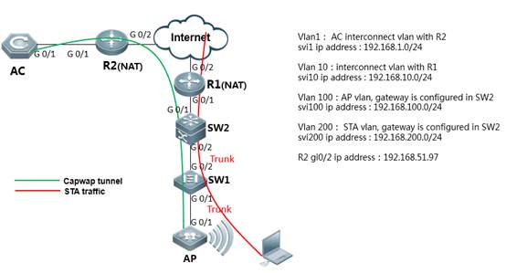
III. Configuration Tips
1) Make sure that AC and AP's firmware should be consistent, using command in CLI "Ruijie>show version"
2) Make sure AP is working on fit mode, using command in CLI "Ruijie>show ap-mode " to check. If it shows fat mode, please modify as follow step:
Ruijie>enable ------>enter the previlege mode
Ruijie#configure terminal ------>enter the config mode
Ruijie(config)#ap-mode fit ------>change to fit-mode
Ruijie(config)#end ------>exit the config mode
Ruijie#write ------>save the config
3) configuration guide summarize:
a. On AC site, configure AC to make sure it can connect to Internet;
b. Map AC's loopback0 ip into public ip, so that AP could establish capwap tunnel with AC by using public ip;
c. On AP site, translate the AP IP and User IP into public ip, so that AP could establish capwap tunnel with AC by using public ip, also user could access to internet resource.
IV. Configuration Steps
1) AC
Step1: configure vlan
Ruijie>enable
Ruijie#configure terminal
Ruijie(config)#vlan 1 ------>the vlan using for AC interconnect with uplink device
Ruijie(config-vlan)#exit
Ruijie(config)#vlan 200 ------>wireless user vlan
Ruijie(config-vlan)#
Step2: configure svi.
Ruijie(config)#interface vlan 200 ------>sta svi ( must config)
Ruijie(config-int-vlan)#exit
Step3: configure wlan-config, create ssid.
Ruijie(config)#wlan-config 1 NAT ------->wlan-config, id=1,SSID named NAT
Ruijie(config-wlan)#enable-broad-ssid ------->enable brocast ssid
Ruijie(config-wlan)#tunnel local ------->enable local forwarding,recommend config under NAT scene
Ruijie(config-wlan)#exit
Step4: configure ap-group, associate wlan-config id with vlan.
Ruijie(config)#ap-group default
Ruijie(config-ap-group)#interface-mapping 1 200 ------->“1”implied wlan-config,“200”implied sta vlan
Ruijie(config-ap-group)#exit
Step5: configure ip addree of ac uplink port and loopback 0
Ruijie(config)#ip route 0.0.0.0 0.0.0.0 192.168.1.254 ------->default route,192.168.1.254 is address of uplink device
Ruijie(config)#interface vlan 1 ------->config svi, layer3 communicate with uplink device
Ruijie(config-int-vlan)#ip address 192.168.1.253 255.255.255.0
Ruijie(config-int-vlan)#interface loopback 0 ------->config loopback0, using for capwap tunnel establish
Ruijie(config-int-loopback)#ip address 1.1.1.1 255.255.255.255 ------->1.1.1.1 should be translate to a public ip addree on egress router
Ruijie(config-int-loopback)#interface GigabitEthernet 0/1
Ruijie(config-int-GigabitEthernet 0/1)#switchport mode trunk ------->connect to uplink device
Step6: Save changes
Ruijie(config-int-GigabitEthernet 0/1)#end
Ruijie#write
Other equipment of AC site
Configure the route to make sure AC can communicate with internet. AC loopback0 address could be forwarded (using NAT) on egress router.
Configuration guide:
a. Correctly config routing、vlan、interface and so on, each equipment could communicate wit
h each other;
b. Egress router config NAT, translate udp port 5246 & 5247 of ac loopback 0 address ( capwap address ) into public port, so that AP can establish capwap tunnel with AC successfully
2) SW1 (access switch, on AP site)
Ruijie>enable
Ruijie#configure terminal
Ruijie(config)#vlan 100 ------>config AP vlan
Ruijie(config-vlan)#vlan 200 ------>config sta vlan
Ruijie(config)#interface gigabitEthernet 0/1 ------>connect to ap
Ruijie(config-int-GigabitEthernet 0/1)#poe enable ------->enable poe (optional config, should be poe switch)
Ruijie(config-GigabitEthernet 0/1)#switchport mode trunk ------>trunk port,transmit ap vlan and sta vlan
Ruijie(config-GigabitEthernet 0/1)#switchport trunk native vlan 100 ------>config ap vlan as native vlan
Ruijie(config-GigabitEthernet 0/1)#interface gigabitEthernet 0/2 ------>connect to core-switch
Ruijie(config-GigabitEthernet 0/2)#switchport mode trunk ------>trunk port,transmit ap vlan and sta vlan
Ruijie(config-int-GigabitEthernet 0/2)#end
Ruijie#write
3) SW2 (core switch, on AP site)
Step1: config vlan, include sta vlan, interconnec vlan with egress router, ap vlan
Ruijie>enable
Ruijie#configure terminal
Ruijie(config)#vlan 10
Ruijie(config-vlan)#exit
Ruijie(config)#vlan 100 ------>ap vlan
Ruijie(config-vlan)#exit
Ruijie(config)#vlan 200 ------>sta vlan
Ruijie(config-vlan)#exit
Step2: config svi
Ruijie(config)#interface VLAN 10 ------->interconnect address with egress router
Ruijie(config-int-vlan)#ip address 192.168.10.254 255.255.255.0
Ruijie(config-int-vlan)#exit
Ruijie(config)#interface vlan 100 ------->AP gateway
Ruijie(config-int-vlan)#ip address 192.168.100.254 255.255.255.0
Ruijie(config-int-vlan)#exit
Ruijie(config)#interface vlan 200 ------->user gateway
Ruijie(config-int-vlan)#ip address 192.168.200.254 255.255.255.0
Ruijie(config-int-vlan)#exit
Step3: config interface
Ruijie(config)# interface GigabitEthernet 0/1 ------->connect to egress router
Ruijie(config-int-GigabitEthernet 0/1)#switchport access vlan 10
Ruijie(config-int-GigabitEthernet 0/1)#interface GigabitEthernet 0/2
Ruijie(config-int-GigabitEthernet 0/2)#switchport mode trunk ------->connect to sw1,transmit ap vlan and sta vlan
Ruijie(config-int-GigabitEthernet 0/2)#exit
Step4: config dhcp service, assign ip address to AP
Ruijie(config)#service dhcp ------->enable dhcp service
Ruijie(config)#ip dhcp pool AP_vlan ------->enable dhcp pool with name AP_vlan
Ruijie(dhcp-config)# option 138 ip 192.168.51.97 ----assign the capwap tunnel address, which is public address of AC loopback0
Ruijie(dhcp-config)# network 192.168.100.0 255.255.255.0 ------->assign the ip address to AP
Ruijie(dhcp-config)# default-router 192.168.100.254 ------->assign the gateway to AP
Ruijie(dhcp-config)#exit
Step5: config dhcp service, assign ip address to STA
Ruijie(config)#ip dhcp pool user_ruijie ------->enable dhcp pool with name user_ruijie
Ruijie(config-dhcp)#network 192.168.200.0 255.255.255.0 ------->assign the ip address to STA
Ruijie(config-dhcp)#default-route 192.168.200.254 ------->assign the gateway to STA
Ruijie(config-dhcp)#dns-server 218.85.157.99 218.85.152.99 ------->assign the dns to STA
Ruijie(config-dhcp)#exit
Step6: config routing
Ruijie(config)#ip route 0.0.0.0 0.0.0.0 192.168.10.1 ------->config static routing,route to egress router.
Step7: save routing
Ruijie(config)#exit
Ruijie#write
4) Configure R1 (Egress router on AP site)
a. configure routing, include default routing、static routing for AP and STA.
b. configure NAT, translate AP address into public address and route to R2 ( egress router on AC site);translate STA address into public address and could connect to internet.
V. Verification
1) STA connect to AP:
Ruijie#sh ac-config client by-ap-name
========= show sta status =========
AP : ap name/radio id
Status: Speed/Power Save/Work Mode, E = enable power save, D = disable power save
Total Sta Num: 1
STA MAC IPV4 Address AP Wlan Vlan Status Asso Auth Net Auth Up time
-------------- -------------- --------------------- ---------------- ----------- --------- ------------------ -------------
2.27b0.169f 192.168.200.1 1414.4b13.c248/1 1 200 65.0M/D/bn WPA2_PSK 0:00:02:06
2) Check AP config on AC:
Ruijie#sh ap-config summary
========= show ap status =========
Radio: E = enabled, D = disabled, N = Not exist
Current Sta number
Channel: * = Global
Power Level = Percent
Online AP number: 1
Offline AP number: 0
AP Name IP Address Mac Address Radio 1 Radio 2 Up/Off time State
AP name AP address AP mac-address 2.4G 5.8G AP connect time AP running state
---------------------------------------- --------------- -------------- ------------------- ------------------- -----------------
1414.4b13.c248 192.168.100.1 1414.4b13.c248 E 1 1* 100 E 0 149* 100 0:01:05:50 Run
2.1.6 FAQ
2.1.6.1 Does the CAPWAP tunnel support cross-NAT networking?
Yes, it supports.
If the AP is on the NAT intranet,
You do not need to configure the static IP address mapping or port mapping for the AP. You just need to configure the source IP address conversion to ensure the connectivity between the AP and the AC.
If the AC is on the NAT intranet,
2. On the egress router, configure mapping for UDP ports 5246 (control channel) and 5247 (data channel) with an AC address indicated by option 138.
2. The IP address of the AC (optional 138 IP address) on the AP is the public network address of the AC after mapping.
If the AP and the AC are on its own NAT intranet, the above three configurations must be met.
2.1.6.2 The CAPWAP tunnel cannot be created.
(1) Communication between the AP and the AC is abnormal.
The AP fails to get the IP address.
The AP fails to get the Option 138 field.
The AP fails to ping the AC to create the tunnel.
The CAPWAP UDP ports 5246 and 5247 are discarded or filtered out by an intermediate device.
(2) The AC and AP are in abnormal status.
The AP cannot go online due to a high AC CPU usage.
show cpu
The AC license is insufficient.
show ac-config
show license
show ap-config summary
The AC and AP version span is large (recommend to use same version for AP and AC).
The AP name is not unique.
19 16:37:19: CD-AC4 %APMG-6-AP_ADD: Add AP(1414.4b5d.03af) fail. Online-AP(1414.4b5d.097f) with same name(XS10A4-1) has exist in this AC
Modifies name of online AP.
Collect the following information and contact Ruijie TAC.
(1) Collect the following information on the AC:
show version
show running
show ac-config
show license
show ap-config summary
show capwap sta
show cpu
show memory
show ip route
show ip interface brief
(2) Collect the following information on the AP:
show version
show ap-mode
show capwap sta
show ip route
show log
show capwap client state
2.1.6.3 How to check the reason why the AP is rejected from going online.
When the link is normal and the AC has received the packet from the AP but the capwap tunnel cannot be established between the AP and the AC, run the show ap-config summary deny-ap command to display the specific cause or in combination with the logs displayed on the AC.
Ruijie#show ap-config summary deny-ap
Deny ap num: 1
Mac Address AP Name Reason
-------------- ---------------------------------------- -----------------
2.4b71.98a1 By conflict
By bind-ap-mac //The AP-MAC binding is rejected. The MAC whitelist bind-ap-mac is enabled on the AC but the MAC of this AP does not exist in ap-config.
By wtp-limit //Indicates that the maximum number of online APs has reached. A common cause is that the license is insufficient or the maximum number of online APs has reached. It is rarely caused by the wtp-limit configuration.
By conflict //Indicates that the AP name conflicts with the MAC name. It is because the AP name has already existed on the AC or other APs of this MAC are online or configured.
By deny-flag //The AC denies the AP to join it. A common cause is that deny-join is configured during networking and debugging.
By ap-auth //Indicates that the AP certification is restricted. Certification by the certificate, serial number or password is enabled on the AC but the AP does not carry any certification information.
By user-class //Indicates the APs belong to different classes. For example, SMB-AP can only access SMB-AC but cannot access ordinary ACs.
By overdue-ap //Indicates the AC has an expired AP. This problem is temporary generally. The AC will automatically clears expired APs and then the expired APs can join the AC again.
By master-ap-mac //Indicates that the satellite AP does not carry the master AP MAC. This problem is temporary generally and is caused by quick AP join during startup of the satellite AP.
By unknown //Indicates an unknown cause.
By radio num //Indicates that interconnection is not supported because the AP has too many RF interfaces. For example, the B7-version AC does not support AM5528.
By vendor id //Indicates that the interconnection is not supported because the AP of another vendor is used.
By new-ap-limit //Indicates that the number of the new APs reaches the upper limit. For example, WS5708 supports up to 100 B9-version APs of wave 2.
By local-limit //Indicates that the number of APs connected to the AC is limited due to the AC protection in VAC scenario. It is possibly because the switch load is unbalanced or the working ACs are insufficient.
By hot-backup //Indicates a hot-backup limit. For example, the AP uses the AP virtualization technology which does not support the hot-backup function. But hot-backup is enabled for this AP in the configuration.
By total-ap-num //The total number of APs (online + offline) and AP tunnels has reached the upper limit. Delete unwanted offline APs.
By none-radio //The AP is rejected because it does not carry radio. This problem is temporary generally and is caused by quick AP join during startup.
When the packet interaction between the AP and the AC is abnormal, capture packets from the intermediate line to locate the packet loss point and troubleshoot the wired network.
2.1.6.4 The AC cannot distribute the configuration to the AP.
[Symptom]
The AC cannot distribute the configuration to the AP.
[Environment]
The AP goes online to the AC across the public network.
[Possible Causes]
(1) The AP does not go online.
(2) The software version conflicts.
(3) The extranet is restricted.
(4) The software has a fault (due to causes such as large version span).
[troubleshooting Steps]
(1) Remotely view whether the AP version is consistent with the AC version and whether the AP has gone online successfully.
(2) Run the show ap-conf run command to check whether the AP has joined the group and whether the active/standby configurations are consistent.
(3) Ping the AP to the AC. If the package size is 1500 bytes, the AC cannot be pinged. The dichotomic test result shows that the maximum package size that can be pinged is 1410 bytes. Modify the control tunnel MTU to 1410 to solve the problem:
ac-controller
capwap ctrl-mtu 1410
[Summary and Precautions]
In the cross-NAT go-online environment, the following problems may occur: the AC configuration cannot be issued, the tunnel cannot be established or is repeatedly established, and the terminal cannot be accessed. After troubleshooting, check whether the large-package communication between the AP and the AC is normal. For repeated tunnel establishment, check whether the NAT entry aging time of the egress is too short by testing the tunnel keepalive time.
2.1.6.5 In the cross-public-network scenario, only part of APs can go online on the AC.
[Symptom]
In cross-public-network mode, only part of APs can go online on the AC.
[Troubleshooting Steps]
(1) Check the network topology, wireless configuration and version.
A. Deploy the APs and the AC (a single AC, no active-standby ACs) across the public network. In hot-backup mode, check whether configurations of the active and standby ACs are the same. Configurations of normal APs and failed APs are exactly the same and the bind-ap-mac configuration is not set.
B. Requests of local users are locally forwarded, and gateway of APs and wireless users and the DHCP address pool are on the local aggregation switch. Troubleshot the local device.
C. The AC, normal APs and abnormal APs are all of the latest version, and online APs are of the same model. It means that the problem is not caused by the version and public network line of the carrier.
(2) Log on to the failed AP to check the AP mode and confirm whether any IP address is obtained. Check whether the large packet can be communicated on the tunnel used for the AP to ping the AC.
Onsite check finds that the failed APs are in fit mode, the IP address can be obtained, and the large packet can be communicated on the tunnel.
(3) After check, we do not find any configuration difference between the access switch and the normal and failed AP interfaces, and the switch is in normal status.
(4) Collect logs and debugs on the failed APs and the AC.
The failed APs are always sending discovery request packets. However, after the show capwap statistics command is run on the AC, the number of received discovery request packets does not increase. It is suspected that the discovery request packets are discarded by intermediate link. Since the APs go online cross the public network and there are normal and failed APs, the problem is not caused by the public network line. It may be caused by the local device.
(5) Check the local device topology, egress EG, aggregation switch, access AC, and APs and capture packets at the uplink interface of the aggregation switch. Discovery request packets of failed APs are found. It is suspected that the packets are discarded at the egress EG device. Because we cannot directly capture packets for analysis at the egress, it is suspected that the application cannot identify the packets or the packets are discarded because traffic of packets from the APs to the AC is too large, and thus some tunnels between APs and the AC cannot be created.
(6) Add the AP network segment to the egress device free of auditing and flow control, and place resources of users at this segment to the EG key channel for preferential forwarding. The test result shows that the failed APs can go online normally. After the resources are moved out of the key channel, the APs go offline after a period of time and cannot go online again.
[Cause]
Traffic on the key channel of the egress traffic control device is too large and thus the interaction packet for creating a tunnel between the AP and the AC is discarded.
[Solution]
Add traffic in the AP IP address segment to the key channel of EG egress, to ensure that the AP packets are preferentially forwarded.
[Other Operation Commands]
Ø On the AC, run the debug apmg join command to check whether the discovery request packet is received.
Ø On the AP, run the debug capwap client fsm command to check whether the packet is successfully sent.
Ø On the AP, run the debug capwap packet command to check whether the discover response packet is received. The prompt is displayed later.
If no response packet is received, run the following command on the AC:
debug efmp packet filter ipv4_sport range 5246 5247 counter 30
Ø If the AP tunnel cannot be created, run the following command on the AC to see whether a prompt is displayed:
debug efmp packet filter ipv4_sip host AP IP address ipv4_sport eq
10000 counter 10
run-system-shell
dmesg
Ø On the AC, run the show capwap ap tunnel id detail command to see the following information:
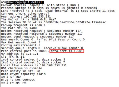
If the data port changes frequently, the traffic table is aging. You are recommended to adjust the channel keepalive time to a smaller value.
ap-config xxx
echo-interval xx (default: 30s; minimum: 5s; maximum: 255s)
2.1.6.6 The AC and AP versions are the same but the AP cannot go online on the AC and the progress stops at Join.
[Symptom]
The AC and AP versions are the same but the AP cannot go online on the AC.
[Analysis]
2. View the log to check the CAPWAP tunnel status of the AP. The result shows the AP has communicated with the AC and its status after the join status is:
DTLS Teardown;
*Jan1 00:01:10: %CAPWAP-6-STATE_CHANGE: (peer - 1) [1.1.1.1] capwap state changed, from <DTLS Setup> to <Join>
*Jan1 00:01:10: %CAPWAP-6-STATE_CHANGE: (peer - 1) [1.1.1.1] capwap state changed, from <Join> to <DTLS TearDown>
2. After confirming the link between the AC and the AP is normal, run the show ap-config summary deny-ap command. The result shows that the fault reason is "By conflict", which means the AP name is not unique in the system and thus the AP cannot join the AC.
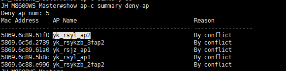
2. After you restore the default settings of the AP or change its name, the AP goes online successfully.
[Summary]
During the go-online process of the AP, the CAPWAP tunnel status is idle-->discover-->DTLS Setup-->Join-->config-->Data Check-->Run respectively. When the CAPWAP tunnel reaches the Run status, the AP has gone online successfully.
If the progress stops when the CAPWAP tunnel reaches the Join status, run the show ap-config summary deny-ap command to display the reason for access denying (the reason is not displayed when the AC version is 11.x and the AP version is 10.x due to a large version span).
The following are common causes for that the progress stops when the CAPWAP tunnel reaches the Join status:
(1) The AP name conflicts.
(2) The versions are inconsistent.
(3) The license is incorrect.
(4) The line has a fault.
(5) The AC has security restrictions, for example, bind-ap-mac.
2.1.6.7 An offline AP is still displayed as "Online" on the AC.
[Symptom]
An offline AP is still displayed as "Online" on the AC.
[Analysis]
(1) Run the show run and show ap-configrun commands to display the configuration and check whether echo-interval is changed. (The default value is 30s.)
2. The result shows that the parameter value is still the default value. On the AC, run the show capwap index detail command several times. The keepalive value remains unchanged. It is suspected that the AP status is not updated on the AC because the keepalive function is disabled. Run the show capwap [ip addr] detail | inc Echo command. The result shows that the echo-interval is 0s.
AC-branch(config-ap)#show capwap 10.121.121.129 detail | in Echo
Echo interval is 0 secs, Dead interval is 0 secs Expire 4294967237 secs
2. Run the show cli record command to display the AC historical command records. The result shows that echo-interval disable is set for the AP-Group of the AP. Delete the configuration, the problem is solved.
[Summary]
This fault is caused by incorrect configuration of the hidden command. echo-interval disable is used to disable the echo function of the CAPWAP tunnel. After configuration, the AP echo function is disabled and the status of the AP is still displayed as "Run" after the AP goes offline. Besides, echo-interval disable is not displayed in the show run command.
The default echo interval between an AP and an AC is 30s. If the AC does not receive any echo packet from the AP within 30s, the AP goes offline.
The AP keeps alive the tunnel by sending an echo request every 30s. After receiving the echo request, the AC sends an echo response. If receiving no echo response within a certain period of time, the AP resends the echo request. The first retransmit starts at the 3rd second. When the time reaches the half of the echo interval, the AP deems that the tunnel is disconnected. The AP performs five retransmits within the 30s echo interval, that is, the 3rd second, 6th second, 12th second, 15th second, and 15th second.
Even if the echo interval is changed to another value, the calculation method for the retransmit time and count is still the same. The echo interval range is 5-255s, which is configured by the echo-interval *command in AP or AP group configuration mode.
2.1.6.8 Most APs cannot go online, online APs often go offline and the tunnel status frequently changes.
I. Symptom
Most APs cannot go online, online APs often go offline and the tunnel status frequently changes.
II. Troubleshooting Steps
(1) Check the network topology, wireless configuration, version, and log.
The version configurations are consistent.
Oct 16 00:24:27: %CAPWAP-5-RETRANS_MAX: (*2) (peer - 47) [172.17.6.30 : 10000] reach maximum retransmit count [5], msg is [configuration update request], seq is [1], elem length is [34].
Oct 16 00:24:27: %CAPWAP-6-PEER_NOTIFY_DOWN: (*2) Peer <172.17.6.30 : 10000 : 5869.6cea.d18d> DOWN, reason <Retransmit MAX>.
The intermediate line may have a fault.
(2) Log on to the failed AP to check the AP mode and confirm whether any IP address is obtained. Check whether the large packet can be communicated on the tunnel used for the AP to ping the AC.
Packet loss is rare during AC ping on the AP. The intermediate line may have a loop or the broadcast traffic is too large.
(3) Log on to the AC and run the clear counters command to clear the interface traffic statistics. After show int counters summary is collected for three consecutive times, the broadcast packets at the interconnected interface increases quickly, as shown in the following figure:
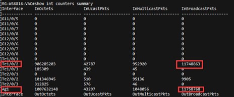
(4) Log on to the interconnected core devices and run the clear counters command to clear the interface traffic statistics. After show int counters summary is collected for three consecutive times, the following figures are displayed:
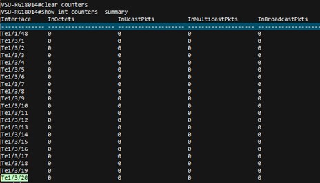
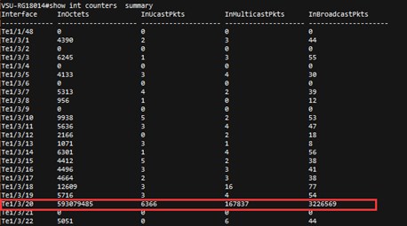
A great amount of broadcast packets increase at the Te1/3/20, indicating that a loop may exist.
(5) After confirming that the device connected to the Te1/3/20 interface is the AP of the access switch, down the Te1/3/20 interface to check whether all the APs under the Te1/3/20 interface go online one after another and the network is recovered.
(6) Log on to the access switch and enable RLDP. It is found that one interface is in down state. Check connection status of the associated device. The result shows that the switch is a private switch and has a loop.
III. Cause
The switch connected to the access switch has a loop at a single port.
IV. Solution
shutdown the loop interface.
V. Summary
(1) When a tunnel cannot be established or is established repeatedly for some APs, a loop may exist. Even if no loop exists, packet loss is impossible when you ping the AC on the AP.
(2) After a similar fault occurs, check the fault scope and active-standby configuration consistency.
(3) If the load balancing policy is incorrectly configured in VAC, the AP may often go online and offline frequently or cannot go online.
(4) In case a loop exists, enable the tree generation or RLDP function and query the switch logs to check the information of the failed port having the loop.
2.1.6.9 Troubleshooting Method and Fault Information Collection for Tunnel Establishment Failure Due to the AP Fault
Troubleshooting Method and Fault Information Collection for Tunnel Establishment Failure Due to the AP Fault
(1) Check the module and version of the AP and AC, and networking topology and solution.
(2) Run the following command to check whether the communication on loopback0 (or capwap ctrl-ip x.x.x.x) between the AP and the AC is normal:
(3) Check the logs on the AP and AC and collect the debug information about the AP and AC.
Log on to the AP:
show log //Collects the AP logs.
more ap_down.txt //Displays the cause for AP offline.
show capwap statistic //Collects the AP tunnel establishment status information. The information can be collected for multiple times, up to consecutive three times.
show capwap client state
//When the AP does not identify efmp, enable debug efmp for the run-system-shell configuration.
run-system-shell cd sbin
./efmp_demo &
exit
Collect the Debug Information
terminal monitor
debug capwap client fsm
debug capwap packet
debug efmp packet filter ipv4_sport range 5246 5247 count 30
Log on to the AC:
show log
show ap-config summary deny-ap
terminal monitor
debug capwap [apip] packet
debug apmg join
debug efmp packet filter ipv4_sport eq 5247 ipv4_sip host [apip] count 10
(4) If no log or debug information is returned from the device end, troubleshoot the intermediate line. Run the traceroute ip tunnel ip source [apip] command to trace the tunnel IP address record route on the AP to view which devices the AP packet has passed.
(5) Perform segmented packet capturing in the dichotomic method to check the sending and receiving of the packet that is used for establishing a tunnel between the AP and the AC and locate the packet loss point.
2.1.6.10 Can the AP and the user be in the same VLAN in the fit AP local forwarding mode?
Yes. The following configurations must be set:
Ruijie(config)# ap-config ap-name
Ruijie(config-ap)# ap-vlan vlan-id (The vlan-id must be the ID of VLAN of the AP and wireless user and must be configured; otherwise, the wireless user cannot obtain the IP address.)
ap-vlan command parsing: In local forwarding mode, the vlan-id configured by this command must be same to that allocated by STA. The actual VLAN of STA is assigned by the access switch of the AP instead of the VLAN configured by this command or assigned by the vlan-group. If the ap-vlan command is not configured, VLAN 1 is used by default.
Note: In local forwarding mode, even when the wireless user resides on VLAN 1, ap-vlan id must be configured on the AP. Otherwise, the wireless user can obtain the IP address of the AP network segment but cannot obtain the IP address of VLAN 1.
2.1.6.11 How to check whether the forwarding mode is local forwarding on the AP?
Run the following command on AP 11.x:
Ruijie#debug fwd dump-mode
wlan 1 tunnel local
Besides, you can query the MAC address table of the connected AP interface on the access switch of the AP. In local forwarding mode, the MAC address table of the wireless user is displayed.
2.1.6.12 When the wireless user resides on VLAN 1 while the AP resides on another VLAN in local forwarding mode, the IP address of the AP VLAN is obtained by the wireless user?
When the wireless user resides on VLAN 1 in local forwarding mode, the ap-vlan of the AP must be configured on the AC.
Ruijie(config)#ap-config 5869.6c84.b278 ---5869.6c84.b278 is the AP name.
Ruijie(config-ap)#ap-vlan 11 ---11 is the AP VLAN ID.
2.2 Fat AP Configuration
2.2.1 FAT AP (General)
Scenario
The APs independently complete the conversation between 802.11 fames and 802.3 frames for communication between the wired and the wireless networks.
Advantage:No need to change the current wired network architecture, simple configuration
Disadvantage:Non-unified management and configuration
I. Requirements
Add a new AP to amplify the coverage of wireless network.
Fat AP brocast 2 ssids, STA can connect to each ssid
II. Network Topology
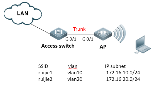
III. Configuration Tips
2.1 Connect console
2.2 Set AP mode fat
2.3 Create Vlan
2.4 Configure Dot1Q
2.5 Configure SSID
2.6 Configure Radio interface
2.7 Associate SSID
2.8 Configure MGMT IP and routing
2.9 Enable Broadcast
2.10 Configure Telnet
2.11 Configure switches
2.12 Other features of AP, like dhcp server、authentication of wireless and encapsulation method, and so on.
IV. Configuration Steps
Step1: Connect console
Default password:ruijie
Step2: Set AP mode fat
Default mode:fit
Ruijie>ap-mode fat
Step3:Create VLAN and dhcp server (ignore dhcp configuration when using other dhcp server)
Ruijie>enable
Ruijie#configure terminal
Ruijie(config)#vlan 1
Note:VLAN 1 is only of local meaning
Ruijie(config-vlan)#vlan 10 ------>create user vlan10
Ruijie(config-vlan)#vlan 20 ------>create user vlan20
Ruijie(config)#service dhcp ------>enable dhcp service
Ruijie(config)#ip dhcp excluded-address 172.16.10.253 172.16.10.254 ------>these address will not assign to user
Ruijie(config)#ip dhcp excluded-address 172.16.20.253 172.16.20.254
Ruijie(config)#ip dhcp pool test_10 ------>config dhcp pool named with test_10
Ruijie(dhcp-config)#network 172.16.10.0 255.255.255.0
Ruijie(dhcp-config)#dns-server 218.85.157.99
Ruijie(dhcp-config)#default-router 172.16.10.254
Ruijie(dhcp-config)#exit
Ruijie(config)#ip dhcp pool test_20 ------>config dhcp pool named with test_20
Ruijie(dhcp-config)#network 172.16.20.0 255.255.255.0
Ruijie(dhcp-config)#dns-server 218.85.157.99
Ruijie(dhcp-config)#default-router 172.16.20.254
Step4: Configure dot1q
Ruijie(config)#interface GigabitEthernet 0/1
Ruijie(config-if)#encapsulation dot1Q 1
Ruijie(config)#interface GigabitEthernet 0/1.10
Ruijie(config-if)#encapsulation dot1Q 10
Ruijie(config)#interface GigabitEthernet 0/1.20
Ruijie(config-if)#encapsulation dot1Q 20
Step5: Configure SSID
Ruijie(config)#dot11 wlan 10
Ruijie(dot11-wlan-config)#broadcast-ssid
Ruijie(dot11-wlan-config)#ssid ruijie1
Ruijie(config)#dot11 wlan 20
Ruijie(dot11-wlan-config)#broadcast-ssid
Ruijie(dot11-wlan-config)#ssid ruijie2
Step6: Configure Radio interface
Ruijie(config)#interface Dot11radio 1/0.1
Ruijie(config-if-Dot11radio 1/0.1)#encapsulation dot1Q 1
Ruijie(config)#interface Dot11radio 1/0.10
Ruijie(config-if-Dot11radio 1/0.10)#encapsulation dot1Q 10 ------>encapsulation vlan 10
Ruijie(config)#interface Dot11radio 1/0.20
Ruijie(config-if-Dot11radio 1/0.20)#encapsulation dot1Q 20 ------>encapsulation vlan 20
Ruijie(config)#interface Dot11radio 2/0.10
Ruijie(config-if-Dot11radio 2/0.10)#encapsulation dot1Q 10 ------>encapsulation vlan 10
Ruijie(config)#iinterface Dot11radio 2/0.20
Ruijie(config-if-Dot11radio 2/0.20)#encapsulation dot1Q 20 ------>encapsulation vlan 20
Step7:Associate SSID
Ruijie(config)#interface Dot11radio 1/0
Ruijie(config-if-Dot11radio 1/0)#channel 1
Ruijie(config-if-Dot11radio 1/0)#power local 100
Ruijie(config-if-Dot11radio 1/0)#wlan-id 10
Config interface wlan id:10, SSID:ruijie1 // success log
Ruijie(config)#interface Dot11radio 1/0.1
Ruijie(config-if-Dot11radio 1/0.1)#wlan-id 20
Config interface wlan id:20, SSID:ruijie2 // success log
Ruijie(config)#interface Dot11radio 2/0
Ruijie(config-if-Dot11radio 2/0)#channel 149
Ruijie(config-if-Dot11radio 2/0)#power local 100
Ruijie(config-if-Dot11radio 2/0)#wlan-id 10
Config interface wlan id:10, SSID:ruijie1 // success log
Ruijie(config)#interface Dot11radio 2/0.1
Ruijie(config-if-Dot11radio 2/0.1)#wlan-id 20
Config interface wlan id:20, SSID:ruijie2 // success log
Note:Must follow up step 5、6、7 sequences exactly,check wifi signal after step 7
Step8:Configure MGMT IP and routing
Ruijie(config)#interface BVI 1 ------>configure MGMT IP address,vlan 1 map bvi 1
Ruijie(config-if)#ip address 172.16.1.253 255.255.255.0
Ruijie(config)#interface bvi 10
Ruijie(config-if-BVI 10)#ip address 172.16.10.253 255.255.255.0
Ruijie(config)#interface bvi 20
Ruijie(config-if-BVI 20)#ip address 172.16.20.253 255.255.255.0
Ruijie(config)#ip route 0.0.0.0 0.0.0.0 172.16.1.254
Ruijie(config)#end
Ruijie#write
Step9:Enable Broadcast
Ruijie(config)#data-plane wireless-broadcast enable
Note:If dhcp server is configured on uplink equipment, please enable wireless brocast function on AP, otherwise, STA obtain dhcp address in unstable situation.
Step10:Config telnet
Ruijie(config)#line vty 0 4
Ruijie(config-line)#password ruijie
Ruijie(config-line)#exit
Ruijie(config)#enable password ruijie
Step11:Config switch
Access_switch:
Aggregate_switch(config)#vlan 1
Aggregate_switch(config-vlan)#exit
Aggregate_switch(config)#interface vlan 1
Aggregate_switch(config-VLAN 1)#ip address 172.16.1.254 255.255.255.0
Aggregate_switch(config)#interface vlan 10
Aggregate_switch(config-VLAN 10)#ip address 172.16.10.254 255.255.255.0
Aggregate_switch(config)#interface vlan 20
Aggregate_switch(config-VLAN 20)#ip address 172.16.20.254 255.255.255.0
Aggregate_switch(config-VLAN 20)#exit
Aggregate_switch(config)#interface gigabitEthernet 0/1 // downlink to AP
Aggregate_switch(config-GigabitEthernet 0/1)#switchport mode trunk
Access_switch(config)#interface gigabitEthernet 0/2 //access switch uplink
Access_switch(config-GigabitEthernet 0/2)#switchport mode trunk
Tip:
Vlan 10, “10”represent vlan-id 10; dot11 wlan 10, “10”represent wlan-id 10.
Vlan 20, “20”represent vlan-id 20; dot11 wlan 20, “20”represent wlan-id 20.
V. Verification
1) Check whether WIFI signal has been broadcasted or not with command “show dot mb” on AP.
2) Check WIFI signal strength with command “show dot a a” on AP.
3) Check ip address and ping gateway
2.2.2 FAT AP (for wall AP)
Scenario
The APs independently complete the conversation between 802.11 fames and 802.3 frames for communication between the wired and the wireless networks.
Advantage:No need to change the current wired network architecture, simple configuration
Disadvantage: Non-unified management and configuration
I. Requirements
Add a new AP to amplify the coverage of wireless network.
Tip:Only applicable for AP110-W and AP120-W
II. Network Topology
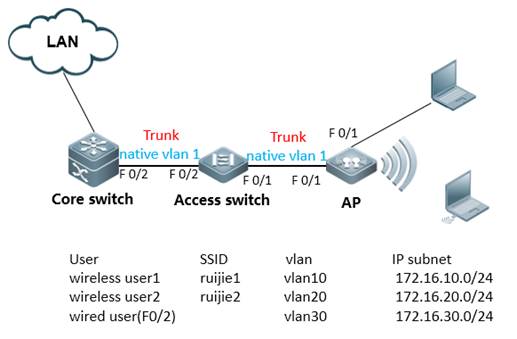
Tip:Access switch should support to set trunk port and native vlan
III. Configuration Tips
2. AP telnet management
2. Enter privileged mode
2. Set AP to fit mode
2. Set enable pwd
2. Save config file
2. Reconnect telnet
2. Create Vlan
2. Config Wan interface Dot1Q
2. Create SSID
2. Create radio sub-interface
2. Associate SSID
2. Enable wireless Broadcast
2. IP setting and routing
2. Configure switches
IV. Configuration Steps
AP configure
Port indexing:
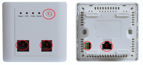
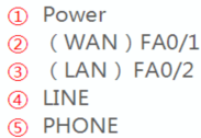
Note:AP130-W default mode: Fit.
Default IP: 192.168.110.1
Default PWD: ruijie
Firmware version: From 10.4(1b19)p2 173487 to the latest version
Fa0/1(locate in the back of panel) default IP:2.168.110.1/24
Fa0/2(locate in the front of panel) default IP:2.168.111.1/24
Firmware version: prior to 10.4(1b19)p2 173487
Fa0/1(locate in the back of panel) default IP:2.168.1.1/24
Fa0/2(locate in the front of panel) default IP:2.168.2.1/24
IV. Configuration Steps
Step1. AP telnet management (take the latest firmware for example)
1) Power on AP, connect PC to FA0/1(in the back)
:PC---POE---(FA0/1)AP
2) PC IP address: 192.168.110.2
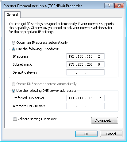
3) Telnet to AP
telnet 192.168.110.1
User Access Verification
Password:ruijie
2. Enter privilege mode
Ruijie>enable
Password:apdebug
Ruijie#
2. Set ap to fat mode
Ruijie#ap-mode fat
apmode will change to FAT.
Note:after mode change,FA0/1、FA0/2 change to layer 3 port,FA0/1 IP address:2.168.110.1/24,FA0/2 IP address:2.168.111.1/24
2. Set enable password
Ruijie(config)#enable password ruijie
2. Save config file
Ruijie#write
2. Create vlan
Ruijie(config)#vlan 10 ------>wireless user1 vlan
Ruijie(config-vlan)#vlan 20 ------>wireless user2 vlan
Ruijie(config-vlan)#vlan 30 ------>wired user vlan
Note:VID 10 is only of local meaning
Ruijie(config-vlan)#exit
2. IP setting
Ruijie(config)#interface BVI 30 ------>bvi 30 map to vlan 30
Ruijie(config-if-bvi)#ip address 172.16.30.100 255.255.255.0
Ruijie(config-if-bvi)#interface Fastethernet 0/2
Ruijie(config-if- Fastethernet )#encapsulation dot1Q 30 ------>port 1 (in the front of panel) encapsulation vlan30
Ruijie(config-if- Fastethernet )#line vty 0 4 ------>configure telnet password
Ruijie(config-line)#password ruijie
Ruijie(config-line)#login
2. Reconnect
1) PC connect to FA0/2 (front panel)
PC-(FA0/2) AP
2) PC IP address 172.16.30.10
3) Telnet AP
telnet 172.16.30.100
User Access Verification
Password:ruijie
Ruijie>enable
Password:Ruijie
2. Configure interface fa0/1
Ruijie(config)#interface fastEthernet 0/1
Ruijie(config-if-FastEthernet 0/1)#encapsulation dot1Q 30 ------>should be consistent with fa0/2 vlan
Ruijie(config-if-FastEthernet 0/1)#interface fastEthernet 0/1.10
Ruijie(config-if-FastEthernet 0/1.2)#encapsulation dot1Q 10 ------> encapsulate sub-interface
Ruijie(config-if-FastEthernet 0/1.2)#interface fastEthernet 0/1.20
Ruijie(config-if-FastEthernet 0/1.3)#encapsulation dot1Q 20
2. Define SSID
Ruijie(config)#dot11 wlan 1
Ruijie(dot11-wlan-config)#ssid ruijie1 ------>SSID “ruijie1”
Ruijie(dot11-wlan-config)#vlan 10 ------>wireless user1 vlan
Ruijie(config)#dot11 wlan 2
Ruijie(dot11-wlan-config)#ssid ruijie2
Ruijie(dot11-wlan-config)#vlan 20
2. Create radio sub-interface
Ruijie(config)#interface dot11radio 1/0.10
Ruijie(config-subif)#encapsulation dot1Q 10 // encapsulte radio sub-interface
Ruijie(config-subif)#mac-mode fat
Ruijie(config-subif)#interface dot11radio 1/0.20
Ruijie(config-subif)#encapsulation dot1Q 20 // encapsulte radio sub-interface
Ruijie(config-subif)#mac-mode fat
2. Associate SSID
Ruijie(config)#interface dot11radio 1/0
Ruijie(config-if-Dot11radio 1/0)#wlan-id 1
Ruijie(config)#interface dot11radio 1/0.1
Ruijie(config-if-Dot11radio 1/0.1)#wlan-id 2
Note: MUST follow step 9,10,11,12 sequences exactly. check wifi signal after step 12
2. Enable wireless broadcast
Ruijie(config)#data-plane wireless-broadcast enable
2. Configure routing
Ruijie(config)#ip route 0.0.0.0 0.0.0.0 172.16.30.1
2. Configure DHCP service (optional feature)
Ruijie(config)#service dhcp ------>enable dhcp service
Ruijie(config)#ip dhcp excluded-address 172.16.10.1
Ruijie(config)#ip dhcp excluded-address 172.16.20.1
Ruijie(config)#ip dhcp excluded-address 172.16.30.1
Ruijie(config)#ip dhcp excluded-address 172.16.30.100
Ruijie(config)#ip dhcp pool ruijie1
Ruijie(dhcp-config)#network 172.16.10.0 255.255.255.0
Ruijie(dhcp-config)#dns-server 218.85.157.99
Ruijie(dhcp-config)#default-router 172.16.10.1
Ruijie(dhcp-config)#exit
Ruijie(config)#ip dhcp pool ruijie2
Ruijie(dhcp-config)#network 172.16.20.0 255.255.255.0
Ruijie(dhcp-config)#dns-server 218.85.157.99
Ruijie(dhcp-config)#default-router 172.16.20.1
Ruijie(dhcp-config)#exit
Ruijie(config)#ip dhcp pool ruijie3
Ruijie(dhcp-config)#network 172.16.30.0 255.255.255.0
Ruijie(dhcp-config)#dns-server 218.85.157.99
Ruijie(dhcp-config)#default-router 172.16.30.1
Ruijie(config)#interface bvi 10
Ruijie(config-if-BVI 1)#ip address 172.16.10.253 255.255.255.0
Ruijie(config-if-BVI 1)#interface bvi 20
Ruijie(config-if-BVI 2)#ip address 172.16.20.253 255.255.255.0
2. Save config file
Ruijie(dhcp-config)#end
Ruijie#write
Access switch:
2. configure interface
Ruijie>enable
Ruijie#configure terminal
Ruijie(config)#interface fastEthernet 0/1
Ruijie(config-if-FastEthernet 0/1)#switchport mode trunk
Ruijie(config-if-FastEthernet 0/1)#interface fastEthernet 0/2
Ruijie(config-if-FastEthernet 0/2)#switchport mode trunk
2. Create vlan
Ruijie(config)#vlan 10
Ruijie(config-vlan)#vlan 20
Ruijie(config-vlan)#vlan 30
Ruijie(config-vlan)#exit
2. Save config file
Ruijie(config)#end
Ruijie#write
Core switch:
2. Configure interface
Ruijie>enable
Ruijie#configure terminal
Ruijie(config)#interface fastEthernet 0/2
Ruijie(config-if-FastEthernet 0/2)#switchport mode trunk
Ruijie(config-if-FastEthernet 0/2)#exit
2. Create vlan
Ruijie(config)#vlan 10
Ruijie(config-vlan)#vlan 20
Ruijie(config-vlan)#vlan 30
Ruijie(config-vlan)#exit
2. Configure gateway
Ruijie(config)#interface vlan 10
Ruijie(config-if-vlan 10)#ip address 172.16.10.1 255.255.255.0
Ruijie(config-if-vlan 10)#interface vlan 20
Ruijie(config-if-vlan 20)#ip address 172.16.20.1 255.255.255.0
Ruijie(config-if-vlan 20)#interface vlan 30
Ruijie(config-if-vlan 30)#ip address 172.16.30.1 255.255.255.0
Ruijie(config-if-vlan 30)#exit
2. DHCP service (optional feature)
Note: dhcp service can be configured in ap or core switch, reference to ap config in step 15
2. save config file
Ruijie(config)#end
Ruijie#write
V. Verification
1) Check WIFI signal strength
2) Check ip address and ping gateway
2.3 Rate Limit
2.3.1 Fit AP
I. Requirements
To make limited network resources serve more users, ensure that the device supports the traffic rate limit function. When the data traffic accords with the committed rate, data packets are allowed to pass. When the data traffic does not accord with the committed rate, data packets are discarded.
II. Configuration Steps
Configuring Rate Limit on AC for Fit AP
AP based Rate Limit
Ruijie(config)#ap-config ap-name
Ruijie(config-ap)#ap-based { per-user-limit | total-user-limit } {down-streams | up-streams } average-data-rate average-data-rate burst-data-rate burst-data-rate
Assign 800KBps average data rate and 1600KBps burst data rate to each wireless user connected to AP RJAP.
Ruijie(config)#ap-config RJAP
Ruijie(config-ap)#ap-based per-user-l
imit down-streams average-data-rate 800 burst-data-rate 1600
Attention: The unit is 8K Bit = 1K Byte.
Wlan based Rate Limit
AC(config)#wlan-config wlan-id
AC(config-wlan)#wlan-based { per-user-limit | total-user-limit | per-ap-limit } {down-streams | up-streams } average-data-rate average-data-rate burst-data-rate burst-data-rate
Assign 800KBps average data rate and 1600KBps burst data rate to each wireless user connected to WLAN "1".
AC(config)#wlan-config 1 RL
AC(config-wlan)#wlan-based per-user-limit down-streams average-data-rate 800 burst-data-rate 1600
MAC based Rate Limit
AC(config)#ac-controller
AC(config-ac)#netuser mac-address { inbound | outbound } average-data-rate average-data-rate burst-data-rate burst-data-rate
Assign 800KBps average data rate and 1600KBps burst data rate to a single wireless user whose MAC address is 0001-0001-0001.
AC(config)#ac-controller
AC(config-ac)#netuser 0001.0001.0001 inbound average-data-rate 800 burst-data-rate 1600
Notes
The priority of Rate Limit
(1) Netuser
(2) wlan-based peruser
(3) ap-based peruser
III. Verification
2. Connect to wlan and have speed test
2. Display QOS status on AC, execute commands "show dot11 ratelimit"
AC#show dot11 ratelimit wlan
Wlan Id TT_up-a-rt TT_up-b-rt TT_dw-a-rt TT_dw-b-rt PU-up-a-rt PU-up-b-rt PU-dw-a-rt PU-dw-b-rt PA_up-a-rt PA_up-b-rt PA_dw-a-rt PA_dw-b-rt
------- ---------- ---------- ---------- ---------- ---------- ---------- ---------- ---------- ---------- ---------- ---------- ----------
1 0 0 0 0 0 0 800 1600 0 0 0 0
AC#show dot11 ratelimit user
MAC Address up-a-rate up-b-rate down-a-rate down-b-rate
-------------- ------------ ------------ ------------ ------------
2.0001.0001 800 1600 0 0
AC#show dot11 ratelimit ap
AP name:test123, ratelimit info(unit:8kbps):
Upstream : average rate - 0, burst rate - 0
Downstream: average rate - 800, burst rate - 1600
Total-user-limit:
Upstream : average rate - 0, burst rate - 0
Downstream: average rate - 0, burst rate �C 0
2. Total speed limit will be devided equally among all online users when configuring "wlan-based perap" or "ap total-user" on ap.
2.3.2 Fat AP
I. Requirements
To make limited network resources serve more users, ensure that the device supports the traffic rate limit function. When the data traffic accords with the committed rate, data packets are allowed to pass. When the data traffic does not accord with the committed rate, data packets are discarded.
II. Configuration Steps
Configuring Rate Limit on Fat AP
AP based Rate Limit
Format: FatAP(config)#wlan-qos ap-based { per-user-limit | total-user-limit } { down-streams | up-streams } average-data-rate average-data-rate burst-data-rate burst-data-rate
Assign 800KBps average data rate and 1600KBps burst data rate to each wireless user connected to this AP.
FatAP(config)#wlan-qos ap-based per-user-limit down-streams average-data-rate 800 burst-data-rate 1600
Attention: The unit is 8K Bit = 1K Byte.
Wlan based Rate Limit
Format: FatAP(config)#wlan-qos wlan-based {wlan-id |ssid } { per-user-limit | total-user-limit } {down-streams | up-streams } average-data-rate average-data-rate burst-data-rate burst-data-rate
Assign 800KBps average data rate and 1600KBps burst data rate to each STA connected to Wlan ID 1.
FatAP(config)#wlan-qos wlan-based 1 per-user-limit down-streams average-data-rate 800 burst-data-rate 1600
MAC based Rate Limit
Format: FatAP(config)#wlan-qos netuser mac-address { inbound | outbound } average-data-rate average-data-rate burst-data-rate burst-data-rate
Assign 800KBps average data rate and 1600KBps burst data rate to a certain wireless user whose MAC address is 0001-0001-0001
Ruijie(config)#wlan-qos netuser 0001.0001.0001 inbound average-data-rate 800 burst-data-rate 1600
III. Verification
2. Connect to wlan and have speed test.
2. Display QOS status on Fat AP, execute commands "show dot11 ratelimit"
FatAP#show dot11 ratelimit wlan
Wlan Id TT_up-a-rt TT_up-b-rt TT_dw-a-rt TT_dw-b-rt PU-up-a-rt PU-up-b-rt PU-dw-a-rt PU-dw-b-rt PA_up-a-rt PA_up-b-rt PA_dw-a-rt PA_dw-b-rt
------- ---------- ---------- ---------- ---------- ---------- ---------- ---------- ---------- ---------- ---------- ---------- ----------
1 0 0 0 0 0 0 800 1600 0 0 0 0
FatAP#show dot11 ratelimit user
MAC Address up-a-rate up-b-rate down-a-rate down-b-rate
-------------- ------------ ------------ ------------ ------------
2.0001.0001 800 1600 0 0
FatAP#show dot11 ratelimit ap
AP name: test123, ratelimit info (unit:8kbps):
Upstream: average rate - 0, burst rate - 0
Downstream: average rate - 800, burst rate - 1600
Total-user-limit:
Upstream: average rate - 0, burst rate - 0
Downstream: average rate - 0, burst rate - 0
2.3.3 FAQ
2.3.3.1 How to display the rate limit configuration
If the AC configuration is as follows:
wlan-config 1 ruijie
wlan-based per-user-limit down-streams average-data-rate 10 burst-data-rate 10
Method is shown as follow: (same for the AC and the AP)
Command description:
show dot11 ratelimit {wlan | ap | user }
wlan: Indicates displaying all rate limit information of all WLANs.
ap: Indicates displaying all rate limit information of all APs.
user: Indicates displaying all rate limit information of all users.
2.3.3.2 What is the unit of the rate limit parameter in the rate limit command?
8 kbps.
For example, to set the download rate to 80 kbps, the command is
Ruijie(config-wlan)#wlan-based per-user-limit down-streams average-data-rate 10 burst-data-rate 10.
2.3.3.3 Precautions for Rate Limit in Local Forwarding Mode
In local forwarding mode, you can only limit the download traffic but cannot limit the upload traffic from STA to STA, because the traffic from STA to STA passes through the express forwarding path only once.
2.3.3.4 Can rate limit be set for WLAN-based users in local forwarding mode?
No. Because rate limit configured by the wlan-based total-user-limit command is realized on the AC, the configuration is only applicable for WLAN-based users in centralized forwarding mode.
2.3.3.5 Does the AP support multiple rate limits?
AP supports multiple rate limits.
When wlan-based per-ap, ap�Cbased total-user, and netuser are configured simultaneously, the final rate limit is the effect when these three configurations take effect at the same time.
2.3.3.6 Which rate limit mode has a higher priority on the AC?
The AC supports AP-based, STA-based, and WLAN-based rate limit modes. The modes are described as follows:
(1) The rate limit modes wlan-based per-user-limit, wlan-based per-ap-limit intelligent, ap-based per-user-limit, ap-based total-limit intelligent, and netuser all function on STA but only one of them can work on STA at a time. The priority is wlan-based per-user-limit > wlan-based per-ap-limit intelligent > wlan-based per-user-limit > ap-based total-limit intelligent > ap-based per-user-limit.
(2) The rate limit modes wlan-based total-limit, wlan-based per-ap-limit, and ap-based total-limit and the STA-based rate limit modes function on different objects and thus can take effect simultaneously,
2.3.3.7 What’s intelligent rate limit?
AP in 11.x version supports intelligent rate limit. When wlan-based per-ap or ap-based total-user intelligent rate limit is configured, the AP intelligently assigns the total rate to all online users on average.
Command:
wlan-based per-ap-limit { down-streams | up-streams } intelligent
ap-based total-user-limit{ down-streams | up-streams } intelligent
Configuration Method:
Before configuring intelligent rate limit of a certain range, you need to configure the total rate limit in the range. Currently, the following two intelligent rate limit modes are supported:
In wlan-based per-ap-limit mode, the wlan-based total rate limit is configured for the WLAN of all the APs in the AC. If wlan-based per-ap-limit is configured and intelligent rate limit is enabled, all the APs intelligently allocate the total bandwidth to all the STAs in the WLAN on average.
In ap-based total-user-limit mode, a total rate limit is configured to the specified AP. If ap-based total-user-limit is configured and intelligent rate limit is enabled, this AP intelligently allocates the total bandwidth to all the STAs in this AP.
Example:
(1) When the per-ap-limit downlink rate limit of WLAN 1 on the AC is set to 1000 kbps and the intelligent rate limit is enabled, all the APs associated with WLAN 1 allocate 1000 kbps to all STAs of WLAN 1 on average. If five STAs are associated with WLAN 1, then the downlink rate limit is 200 kbps.
Ruijie(config)#wlan-config 1
Ruijie(config-wlan)#wlan-based per-ap-limit down-streams average-data-rate 1000 burst-data-rate 1000
Ruijie(config-wlan)#wlan-based per-ap-limit down-streams intelligent
(2) When the ap-based total-user-limit upload rate limit of AP 320 is set to 500 kbps on the AC and the intelligent rate limit is enabled, AP 320 allocates the 500 kbps to all STAs of AP 320. If five users are associated with AP 320, the upload rate limit of each user is 100 kbps.
Ruijie(config)#ap-config ap320
Ruijie(config-ap)#ap-based total-user-limit up-streams average-data-rate 500 burst-data-rate 500
Ruijie(config-ap)#ap-based total-user-limit up-streams intelligent
2.4 Wireless Security
2.4.1 Wireless Encryption (WPA/WPA2)
I. Requirements
Wireless user need to input password when connect to wireless network.
II. Network Topology
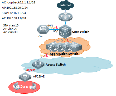
III. Configuration Tips
2. Configure wireless encryption
2. Configure wireless encryption type
2. Configure wireless password
IV. Configuration Steps
2. WPA configuration
WS5708(config)#wlansec 1
WS5708(config-wlansec)#security wpa enable ---->enable wpa
WS5708(config-wlansec)#security wpa ciphers aes enable ---->enable aes encryption
WS5708(config-wlansec)#security wpa akm psk enable ---->psk key management
WS5708(config-wlansec)#security wpa akm psk set-key ascii 1234567890 ---->wifi password, no less than 8 digits
2. WPA2 configuration【recommand】
WS5708(config)#wlansec 1
WS5708(config-wlansec)#security rsn enable ---->enable wpa2
WS5708(config-wlansec)#security rsn ciphers aes enable ---->enable aes encryption
WS5708(config-wlansec)#security rsn akm psk enable ---->psk key management
WS5708(config-wlansec)#security rsn akm psk set-key ascii 1234567890 ---->wifi password, no less than 8 digits
Note: One SSID can support both WPA and WPA2, but two passwords MUST match.
V. Verification
2. Connect to ssid
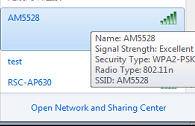
2. Type the key
3. Check Wi-Fi association
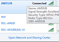

2.4.2 Blacklist&Whitelist
2.4.2.1 STA Whitelist
Scenario
Frame filtering involves the configuration of white list, static blacklist and dynamic blacklist. When AP receives a data frame. It will check the MAC address of this data frame. The process of frame filtering is shown below:
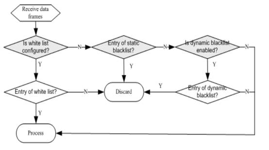
Figure flow of frame filtering
I. Requirements
Configure white list in WIDS configuration mode. When an entry exists in the white list, the corresponding client will pass frame filtering.
II. Network Topology
III. Configuration Tips
Configure whitelist (When an entry exists in the white list, the corresponding client will pass frame filtering)
Cofnigure blacklist (When an entry exists in the black list, the corresponding client will be denied to pass)
IV. Configuration Steps
configure whitelist, sta mac-address:2.27b0.169f, 8ca9.829a.b1ea
WS5302(config)#wids
WS5302(config-wids)#whitelist mac-address 6809.27b0.169f -----> 6809.27b0.169f is allowed to access
WS5302(config-wids)#whitelist max 1024 ----->adjust whitelist capacity (range from 1-1024, optional config)
configure blacklist,sta mac-address:2.27b0.169f, 8ca9.829a.b1ea
WS5302(config)#wids
WS5302(config-wids)#static-blacklist mac-address 6809.27b0.169f ----->6809.27b0.169f is denied to pass
WS5302(config-wids)#static-blacklist max 1024 ----->adjust blacklist capacity (range from 1-1024, optional config)
V. Verification
2. When an entry exists in the white list, the corresponding client will pass frame filtering, STA MAC:2.27b0.169f、 8ca9.829a.b1ea
WS5302#show wids whitelist
------------------ Whitelist Information ------------------
num Mac-address
1 6809.27b0.169f
WS5302#show ac-config client by-ap-name
========= show sta status =========
AP : ap name/radio id
Status: Speed/Power Save/Work Mode, E = enable power save, D = disable power save
Total Sta Num: 1
STA MAC IPV4 Address AP Wlan Vlan Status Asso Auth Net Auth Up time
-------------- --------------- ---------------------------------------- ---- ---- -------------- --------- --------- -------------
2.27b0.169f 192.168.20.1 1414.4b13.c248/1 1 20 52.0M/E/bn WPA2_PSK 0:00:10:02
2. When an entry exists in the black list, the corresponding client will be denied to pass,STA MAC:(6809.27b0.169f、 8ca9.829a.b1ea)
WS5302#show wids blacklist static
------------------ Static Blacklist Information ------------------
num Mac-address
1 6809.27b0.169f
WS5302#show ac-config client by-ap-name
========= show sta status =========
AP : ap name/radio id
Status: Speed/Power Save/Work Mode, E = enable power save, D = disable power save
Total Sta Num: 1
STA MAC IPV4 Address AP Wlan Vlan Status Asso Auth Net Auth Up time
-------------- --------------- ---------------------------------------- ---- ---- -------------- --------- --------- -------------
8ca9.829a.b1ea 192.168.20.2 1414.4b13.c248/1 1 20 58.5M/D/bn WPA2_PSK 0:00:00:24
2.4.2.2 SSID Whitelist
Scenario
Frame filtering involves the configuration of white list, static blacklist and dynamic blacklist. When AP receives a data frame, it will check the MAC address of this data frame. The process of frame filtering is shown below:

Figure flow of frame filtering
I. Requirements
Configure white list in WIDS configuration mode. When an entry exists in the white list, the corresponding client will pass frame filtering.
II. Configuration Tips
Configure whitelist based on SSID (When an entry exists in the white list, the corresponding client will access to ssid)
Configure blacklist based on SSID (When an entry exists in the black list, the corresponding client will be denied to access to ssid)
IV. Configuration Steps
Configure whitelist based on ssid:
WS5302(config)#wids
WS5302(config-wids)#ssid-filter whitelist mac-address 6809.27b0.169f in ruijie ----->6809.27b0.169f is allowed to access to SSID:ruijie
WS5302(config-wids)#ssid-filter whitelist max 256----->adjust whitelist capacity (range from 1-256, optional config)
Configure blacklist based on ssid:
WS5302(config)#wids
WS5302(config-wids)#static-blacklist ssid-mac 6809.27b0.169f in ruijie ----->6809.27b0.169f is denied to access to SSID:ruijie
WS5302(config-wids)#ssid-filter blacklist max 256 ----->adjust blacklist capacity (range from 1-256, optional config)
V. Verification
SSID:ruijie
2. When an entry exists in the white list, the corresponding client will access to ssid,STA MAC:(6809.27b0.169f、 8ca9.829a.b1ea)
WS5302#show wids ssid-filter whitelist in-ssid wireless ---check whitelist
------------------ filter white-mac List Information ------------------
num mac SSID
1 6809.27b0.169f wireless
WS5302#show ac-config client by-ap-name
========= show sta status =========
AP : ap name/radio id
Status: Speed/Power Save/Work Mode, E = enable power save, D = disable power save
Total Sta Num: 1
STA MAC IPV4 Address AP Wlan Vlan Status Asso Auth Net Auth Up time
-------------- --------------- --------------------------- ----- ----- ---- ---- -------------- --------- --------- -------------
2.27b0.169f 192.168.20.1 1414.4b13.c248/1 1 20 58.5M/E/bn WPA2_PSK 0:01:42:11
2. When an entry exists in the black list, the corresponding client will be denied to access to ssid,STA MAC:(6809.27b0.169f, 8ca9.829a.b1ea)
WS5302#show wids ssid-filter blacklist in-ssid wireless ---check blacklist
------------------ filter black-mac List Information ------------------
num mac SSID
1 6809.27b0.169f wireless
WS5302#show ac-config client by-ap-name
========= show sta status =========
AP : ap name/radio id
Status: Speed/Power Save/Work Mode, E = enable power save, D = disable power save
Total Sta Num: 1
STA MAC IPV4 Address AP Wlan Vlan Status Asso Auth Net Auth Up time
-------------- --------------- ---------------------------------------- ---- ---- -------------- --------- --------- -------------
8ca9.829a.b1ea 192.168.20.2 1414.4b13.c248/1 1 20 58.5M/D/bn WPA2_PSK 0:00:10:24
2.4.3 Association Control
2.4.3.1 Association Control Working Principle
Overview
The association control is a method of controlling wireless STA's association behaviors. By grouping STAs, define one of the STAs as the master STA and others as secondary-STAs which must follow the master STA's method, and make the associated wireless network of secondary-STAs be the same as that of the master STA. Therefore, the associated behaviors of wireless terminals can be controlled.
Association control is usually used in the e-bag scenario.
Basic Concept
1) The association control zone: it can be understood as the wireless network made up of one or one group of APs. For a STA group, it can only successfully associate with a certain AP in an association control zone at one time.
2) The terminal package: it's made up of a group of STAs, including the master STA and secondary-STAs. Secondary-STAs cannot be separated from the master STA, associating with certain AP in the control zone alone. It can only follow the master STA; it can only associate with certain AP in the control zone with which the master STA associate.
Working Principle
Divide the scope of the wireless network into several association control zones, and arrange one or several APs in every association control zone, then group the wireless terminal to strictly control the control zones that the terminal can associate with. Take the application of the school e-bag for instance, a school has many classrooms in which wireless APs are installed and the wireless signal travels in the space. When two neighboring classrooms are using the e-bag, the ideal situation is that teachers' and students' computers all associate with local APs, therefore, every class can proceed without interruption. This requires each classroom to be an association control zone, and students' and teachers' computers all associate with local wireless APs.
I. Network Topology
The figure below shows the fit AP framework of the association control application.
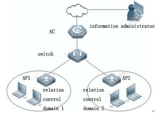
Fit AP networking topology
Premise
The purpose of the association control is to prevent the terminal to perform random associations when there are many wireless networks. The premise of the network configuration is as below:
・ Set each association control zone as a WLAN subnet and allocate a VLAN for each subnet. By this measure, the broadcast or the multicast report is limited in the local control zone,.Thus, the application fluency of the association control zone is ensured.
・ Use different SSIDs for all WLAN subnets. For example, use the association control zone's name as SSID for easier differentiation. It's easier for the master STA and secondary-STAs in the terminal to associate with designate APs in the association control zone.
Working Principle
・ The AC sends all information of the master STA in the terminal package to all APs in the association control zone as per the pre-configured information of the association control zone and the terminal package.
・ Since all the information of the master STA in the terminal package is on the AP's white list, when applying the association control function, the master STA needs to associate with corresponding SSIDs in the control zone first; after the master STA completes the association, the AC will send all secondary-STAs to all APs in the association control zone as per the configuration of the terminal package where the master STA stays, and create the white list, thus, secondary-STAs are allowed to be associated with the local control zone.
・ When the master STA releases association and log off, all corresponding secondary-STAs will be offline and be deleted from the APs'white list in the association control zone.
・ The above process can be briefly summarized as that secondary-STAs follow the master STA; With whichever APs the master STA associates, secondary-STAs must follow and associate with the APs in the association control zone. The corresponding white list is only on the APs of the association zone, and since the list doesn't exist on APs in other association control zones. It ensures that STAs will not perform random associations.
Note: In the fit AP framework, the master STA and secondary-STAs might be distributed to several APs in certain control zones.
2.4.3.2 Association Control Configuration
Overview
The association control is a method of controlling wireless STA's association behaviors. By grouping STAs, define one of the STAs as the master STA and others as secondary-STAs which must follow the master STA's method, and make the associated wireless network of secondary-STAs be the same as that of the master STA. Therefore, the associated behaviors of wireless terminals can be controlled.
Association control is usually used in the e-bag scenario.
Only a wireless client access to the wireless network, and other wireless terminals can access the radio. Generally used in school teaching environment, such as students can access the wireless client only after a teacher connect to the wireless
Advantages: increase wireless security, ensure the use of the wireless network.
Disadvantages: a waste of radio resources, the need for additional configuration, can only be used in Fit mode.
I. Requirements
Secondary-sta will connect to wireless network if primary-sta is connected.
II. Network Topology
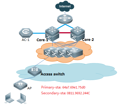
III. Configuration Tips
2. Configure the termination package
2. Configure the control zone
2. Enable the association control
IV. Configuration Steps
2. Configure termination package
AC-1(config)#package 5-2
AC-1(config-package)#primary-sta 64a7.69e1.75d0 ----->configure primary-STA
AC-1(config-package)#secondary-sta 0811.9692.244c ----->configure secondary-STA,add all secondary sta.
2. Configure control zone
AC-1(config)#control-zone js1----->control zone name is js1
AC-1(config-czone)#ap ap220-e ----->add relevant ap to the control zone
AC-1(config-czone)#ap ap220-i ----->add relevant ap to the control zone
AC-1(config)#control-zone js2
AC-1(config-czone)#ap ap320-1
AC-1(config-czone)#ap ap320-2
2. Enable associationg control
AC-1(config)#assoc-control
2. Save config file
AC-1(config)#end
AC-1#write
V. Verification
2. Secondary-sta will connect to the wireless network if Primary-sta is connected.
2. AC show ac-config client, check sta online or not.

2. Use command "show run" on AP, check the whitelist

2.4.4 DHCP Snooping + ARP-Check
Overview
ARP check function filters all ARP packets on the logic interface and drops all illegal ARP packets, avoiding the ARP spoofing in the network and improving the network stability.
Ruijie switches support multiple IP security application (such as IP Source Guard, global IP+MAC binding, port security) which effectively filter the user IP packets and avoid the illegal user to use the network resources. The ARP check function generates the corresponding ARP filtering information according to the legal user information (IP or IP+MAC), implementing the illegal ARP packet filtering in the network.
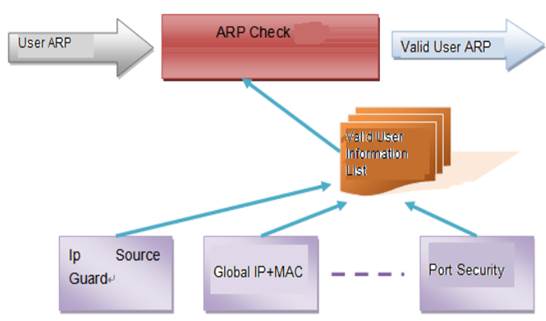
ARP check and other security function
ARP check function is enabled or disabled according to the current security function running state on the switch. Enabling/disabling the following functions may trigger to enable/disable the ARP Check function:
Global IP+MAC binding
802.1X IP authorization
IP Source Guard
GSN binding
Adding the legal user for the first time or removing the last legal user may trigger to enable/disable the ARP check function:
IP+MAC binding mode for the port security
IP-only mode for the port security
Note: ARP check is enabled no matter whether there is security configuration. If there is no legal user on the port, all the ARP packets from this port will be discarded.
DHCP Snooping and ARP Check
As with ARP Inspection, ARP Check checks all the ARP messages travelling through the switch. DHCP Snooping needs to offer the database information for ARP Check to use. After receiving an ARP message, the ARP Check-enabled switch queries the database bound by the DHCP Snooping. The ARP message is learned and forwarded only when its source MAC, source IP and port are matched or otherwise it is dropped.
II. Network Topology
III. Configuration Tips
2. AC-1 enable dhcp snooping, configure uplink port as trust port
2. Configure arp-check
2. Clear arp and proxy arp table
IV. Configuration Steps
2. AC-1 enable dhcp snooping and configure trust port
AC-1(config)#ip dhcp snooping ----->enable dhcp snooping on config mode
AC-1(config)#interface gigabitEthernet 0/1
AC-1(config-if-GigabitEthernet 0/1)#ip dhcp snooping trust ----->set trust port
2. Configure arp-check (note: sta reconnect to ap when arp-check enable)
1) Scene1: Without web-auth
AC-1(config)#wlansec 1
AC-1(config-wlansec)#ip verify source port-security ----->enable ip source-guard
AC-1(config-wlansec)#arp-check ----->enable arp-check
2) Scene2: enable web-auth
AC-1(config)#web-auth dhcp-check ----->enable dhcp-check when enable web-auth
AC-1(config)#http redirect direct-arp 192.168.51.1 ------>must exclude STA's gateway arp packets
AC-1(config)#wlansec 1
AC-1(config-wlansec)#arp-check ----->enable arp-check
Note:when enable web-auth, configure anti-arp gateway spoofing to filter gateway arp spoofing:
1. Upgrade to RGOS11.x;
2. Config anti-arp gateway spoofing in wlansec mode.
AC-1(config)#wlansec 1
AC-1(config-wlansec)#anti-arp-spoofing ip 172.29.6.254 (172.29.6.254 represent user's gataway)
note: anti-arp-spoofing capacity is 64
2. Clear arp and proxy_arp table
AC-1#clear arp-cache
AC-1#clear proxy_arp
V. Verification
2. Wireless user ARP hardware binding info.

2. Try manually ip setting, fails to ping gateway.
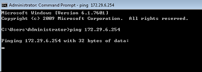
2.4.5 Countermeasure against Rogue AP
Overview
Compared with wired network, WLAN is convenient to deploy, flexible to use, cost-efficient and easy to expand, and is thus applied more and more widely. However, due to the openness of WLAN channel, the wireless networks are susceptible to a wide array of threats such as unauthorized APs, ad-hoc networks and different kinds of protocol attacks.
Therefore, security has become an important factor inhibiting the development of WLAN.
WIDS (Wireless Intrusion Detection System) provides early detection of malicious attacks and intrusions and helps the network administrator to proactively discover the hidden defects of network and take necessary countermeasures.
Currently, WIDS mainly provides the following features:
Rogue device detection, countermeasure
IDS attack detection
Frame filtering (black list and white list)
User isolation
Basic concept of rogue device countermeasure:
Rogue device: Unauthorized or malicious device on the network. It can be an illegal AP, illegal bridge or unauthorized Ad-hoc device.
Rogue AP: An unauthorized or malicious AP on the network, such as an unauthorized AP, misconfigured AP or an attacker operated AP.
Rogue AP Countermeasure is used to attack fake authentication release frame sent by rogue AP address in the list to countermeasure rogue AP.
I. Requirements
Monitor Rogue AP and configure countermeasures.
II. Network Topology
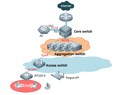
III. Configuration Tips
2. Configure device mode
2. Configure countermeasure
IV. Configuration Steps
2. Configure AP as monitor or hybrid mode
AC(config)# ap-config ap220-e
AC(ap-config)# device mode monitor or AC(ap-config)# device mode hybrid
Note:
Monitore mode: monitor/attack rogue AP only
Hybrid mode: monitor/attack rogue AP and forward user date as normal AP (less monitor performance)
2. Configure countermeasure rogue ap static list
Firmware version 11.X:
AC (config)#ap-config AP220-I ----->enter ap-config mode
AC(config-ap)#device mode monitor
AC(config-ap)#scan-channels 802.11b channels 1 2 3 4 5 6 7 8 9 10 11 12 13 --->configure the scanning channel of 2.4G
AC(config-ap)#scan-channels 802.11a channels 149 153 157 161 165 --->configure the scanning channel of 5G
AC(config)#wids ----->enter wids mode
AC(config-wids)#countermeasure enable ----->enable countermeasure
AC(config-wids)#countermeasures channel-match ----->enable channel-based containment
AC(config-wids)#countermeasures mode config ----->choose the countermeasures mode
AC(config-wids)#device attack mac-address 061b.b120.700c ----->add static list of attack, add rogue AP bssid:061b.b120.700c. you can scan rogue AP with wirelessmon to confirm the bssid.
Appendix:
Base on the circumstance that AP740-I has three RF cards, we can use radio 1 and radio 2 for wifi service, and use radio 3 to countermeasure other rouge aps. The graphic configurations are shown below:
AC (config)#ap-config AP740-I ----->entwe into the specific ap
AC (config-ap)#radio-type 3 802.11b ----->config the third RF card to be 2.4g
AC (config)#ap-config AP740-I ----->enter ap-config mode
AC(config-ap)#device mode monitor radio 3 ----->choose the radio 3 to be the countermeasure role
AC(config-ap)#scan-channels 802.11b channels 1 2 3 4 5 6 7 8 9 10 11 12 13 --->configure the scanning channel of 2.4G
AC(config-ap)#scan-channels 802.11a channels 149 153 157 161 165 --->configure the scanning channel of 5G
AC(config)#wids ----->enter wids mode
AC(config-wids)#countermeasure enable ----->enable countermeasure
AC(config-wids)#countermeasures channel-match ----->enable channel-based containment
AC(config-wids)#countermeasures mode config ----->choose the countermeasures mode
AC(config-wids)#device attack mac-address 061b.b120.700c ----->add static list of attack, add rogue AP bssid:061b.b120.700c. you can scan rogue AP with wirelessmon to confirm the bssid.
Countermeasure mode concept:
Use this command to configure the device countermeasures mode. Use the no form of this command to restore the default setting.
countermeasures mode { all | adhoc | config | rogue | ssid }
no countermeasures mode { all | adhoc | config | rogue | ssid }
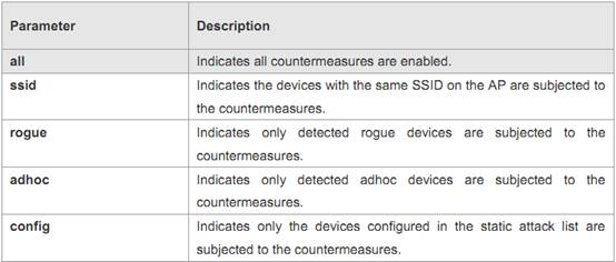
Optional configuration:(You can use below commands when countermeasure is inefficient)
2. Unknown STA Detection (unicast countermeasure).
Ruijie#configure terminal
Ruijie(config)#wids
Ruijie(config-wids)#device unknown-sta dynamic-enable ----->enable the unknown STA detection and containment function
Ruijie(config-wids)#device unknown-sta mac-address 1234.1234.1234----->configure the unknown STA list entry
2. Add an entry to the permissible list
Ruijie#configure terminal
Ruijie(config)#wids
Ruijie(config-wids)# device permit mac-address 1234.1234.1236----->configure the permissible MAC list 1234.1234.1236
Ruijie(config-wids)# device permit ssid test----->configure the permissible SSID list test
Ruijie(config-wids)# device permit vendor bssid 1234.1234.1236----->configure the permissible vendor list
2. Configure countermeasure parameters
Ruijie#configure terminal
Ruijie(config)#wids
Ruijie(config-wids)#countermeasures interval 2000-----> configure countermeasures interval 2000ms
Ruijie(config-wids)#countermeasures ap-max 256---> configure the maximum number of contained devices once,ranging from 1 to 256. The default maximum number of countered devices is 30.
Ruijie(config-wids)#countermeasures rssi-min 5 --->configure the minimum containment RSSI,ranging from 0 to 75(This value is not recommended to set too small)
Ruijie(config-wids)#device detected-ap-max 100 --->configure the maximum number of detected APs,ranging from 1 to 4096.
Ruijie(config-wids)#device aging duration 1000 --->configure the aging duration of the detected devices,ranging from 500 to 5000 seconds.
V. Verification
Wireless users can not connect to rogue APs or packets loss.
2.4.6 User Isolation
Overview
Enable the isolation function in the wireless device (the AP or the AC). When the device receives a certain user's report, it will judge if it's the same device according to the resource port and the destination port in the information it forwards. If the resource port and the destination port are on the same device, then discard the report; Otherwise, normally forward the report.
The user can also add the permitted interflow user table entry through configuring isolation permit list. If the MAC address of two users on the same AP or AC is added into the user isolation permit list, then these two users can visit each other.
The process of enabling the user isolation function is showed in the picture below:
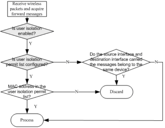
I. Requirements
To protect user data, network administrator usually isolate traffic between STA connected to the same AP/AC/SSID
II. Network Topology
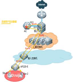
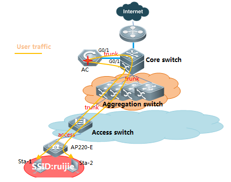
III. Configuration Tips
1) Enable user isolation
2) Define isolation mode
3) Define permit-mac
IV. Configuration Steps
Fit AP configuration
1. Isolation types: per-AC isolation, per-AP isolation, per AC-SSID isolation, per AP-SSID isolation:
1) Isolate user associated to the same AC
AC(config)#wids
AC(config-wids)#user-isolation ac enable
2) Isolate user associated to the same AP
AC(config)#wids
AC(config-wids)#user-isolation ap enable
3) isolate user associated to the same AC+SSID
AC(config)#wids
AC(config-wids)#user-isolation ssid-ac enable
4) isolate user associated to the same AP+SSID
AC(config)#wids
AC(config-wids)#user-isolation ssid-ap enable
2. Configure permit mac, user in permit-mac list, will be unrestricted.
AC(config)#wids
AC(config-wids)#user-isolation permit-mac 0811.9692.244c
Note:User Isolation feature is only for L2 user isolation
Fat AP configuration
2. Isolation types: per-AP isolation, per AP-SSID isolation
1) Isolate user associated to the same AP
Ruijie(config)#wids
Ruijie (config-wids)#user-isolation ap enable
2) Isolate user associated to the same AP+SSID
Ruijie (config)#wids
Ruijie (config-wids)#user-isolation ssid-ap enable
2. Configure permit mac, user in permit-mac list, will be unrestricted.
AP(config)#wids
AP(config-wids)#user-isolation permit-mac 0811.9692.244c
Note:User Isolation feature is only for L2 user isolation
V. Verification
2. WIFI users are isolated from other local STA
2. User in permit-MAC list is allowed to communicate with others.
2.4.7 Conceal SSID (Disable SSID Broadcast)
Overview
On the WLAN, the AP periodically broadcasts the SSID information to notify other entities of the existence of the wireless network. Wireless users use the wireless network interface cards (NICs) to search SSIDs and detect the wireless network. The SSID broadcasting function can be enabled to prevent the wireless network from being searched and connected by unauthorized users based on the SSID.
Configure Conceal SSID:
For Fit AP, configuring on AC
AC(config)#wlan-config 1 conceal
AC(config-wlan)#no enable-broad-ssid ---> disable SSID broadcast
AC(config)#ap-group default
AC(config-group)#no interface-mapping 1 1 --->online user will be forced offline
AC(config-group)#interface-mapping 1 1 ---> map wlan-id to vlan-id again
AC(config-group)#end
AC#write
For Fat AP, configuring on AP
FatAP(config)#dot11 wlan 1
FatAP(dot11-wlan-config)#no broadcast-ssid ---> disable SSID broadcast
FatAP(config)#interface dot11radio 1/0
FatAP(config-if-Dot11radio 1/0)#no wlan-id 1 --->online user will be forced offline
FatAP(config-if-Dot11radio 1/0)#wlan-id 1 ---> map wlan-id to vlan-id again
Verification:
Your wireless client should unable to search this wlan, and you need to join this wlan manually.
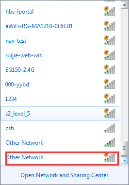
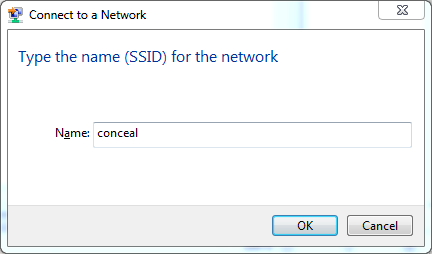
2.4.8 FAQ
2.4.8.1 Will own Ruijie APs be countered if the wireless AP countering is enabled?
No in fit mode but yes in fat mode.
The becon frame contains a friendly flag which is used to judge whether the AP is a friendly AP. If the APs are all associated with the Ruijie AC, the friendly flags are the same by default, and Ruijie APs are not countered. When the friendly flags are modified to be different, countering is enabled for APs on Ruijie AC. By default, the friendly flag for all Ruijie APs is the same and thus Ruijie APs are not deemed as rogue APs. The configuration method of the friendly flag is as follows:
![]()
2.4.8.2 How to display rogue APs?
Run the show wids detected rogue ap command.
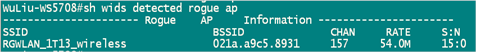
2.4.8.3 How to display all SSID in the environment?
Run the show wids detected all command.
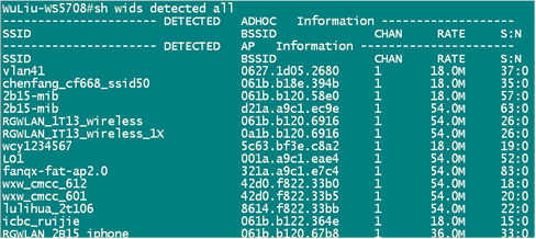
2.4.8.4 How to judge whether an AP is under countering?
2. Symptom
Users in Building 12 in old campus cannot be associated with China UNICOM-WLAN SSID. Users associated with this SSID are often disconnected and cannot visit the Internet.
Onsite Problem Locating:
In the dormitory with poor user experience, we found that after the computer is connected to China UNICOM-WLAN SSID, the SSID signal often disappears, the ping packet loss rate is high, and the computer is often disconnected from the Internet.
2. Possible Cause
The AP countering function is configured.
2. Troubleshooting Steps
We used a professional tool (Ominpeek) to capture packets in the corridor on the second floor. A great amount of deauthentication (Deauth) packets were found, as shown in Figure 1. We located the AP (MAC address: 9614 4B1B 34FA) of the broadcast Deauth packet and found that it is an AP of China Unicom. After searching on the AC, we found that the i-Share AP was deployed here, covering the surrounding six rooms. But the log shows that the AP does not send any Deauth packet. Then it is confirmed that it is not this AP that sends the invalid Deauth packet.
After analysis, we suspected that there was a rogue AP. The rogue AP sent dissociated Deauth packets to the associated users in the name of China UNICOM AP, as shown in Figure 2. According to signal strength comparison, the signal strength of normal packet was about 26%, while that of the Deauth packet sent by the rogue AP was 100%, as shown in Figure 3. Therefore, we confirmed the existence of the rogue AP and knew that the rogue AP was close to the test place, resulting in frequent disconnection of users within the coverage of this rogue AP from the WLAN.
Figure 1: Too many Deauth packets
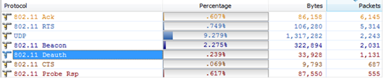
Figure 2: The rogue AP broadcasting Deauth packets in the name of China UNICOM MAC
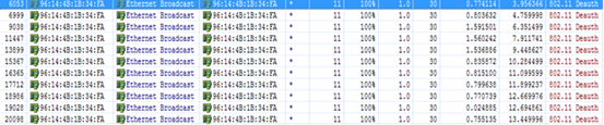
Figure 3: Signal length of normal packets lower than that of Deauth packets
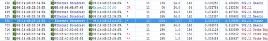
2. Collecting the Fault Information
Locating the Rogue AP
During onsite survey, we found an AP of another carrier near the test place and the data light of this AP flashed very fast, indicating transmission of a great amount of data. This AP was suspected to be a rogue AP.
To confirm it, we powered off this AP and captured packets at the air interface on site. The result showed that the percentage of deauth packets decreased immediately from 0.239% to 0.031%, as shown in Figure 4.
Figure 4: Decreasing of deauth packets after the rogue AP is powered off
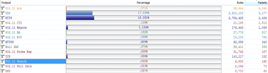
Then, the users can be associated with the AP and access the WLAN. No ping packet is lost.
After the carrier's AP is restored, the problem occurs again. Therefore, it can be confirmed that the carrier's AP is a rogue AP and the AP countering function is enabled.
2.5 WLAN Roaming
2.5.2 Layer-2 Inter-AC Roaming Configuration
Scenario
When a STA (station, wireless workstation) roams to the coverage edge of two adjacent APs, STA will associate with the new AP and disconnect from the original AP, and uninterrupted network connection is maintained during this process. Inter-AC Roaming need to establish mobility group between two AC in order to interaction data and ensure that users roam without perception.
I. Requirements
AP1 and AP2 establish CAPWAP with different AC in fit mode. STA need roaming from 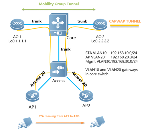
AP1 to AP2.
II. Configuration Steps
Before configure roaming, please make sure that the network deployment has been completed, the data communication is normal.
2. Configure ip route and make AC-1 and AC-2 are reachable
Core Switch:
core(config)#ip route 1.1.1.1 255.255.255.255 192.168.30.2
core(config)#ip route 2.2.2.2 255.255.255.255 192.168.30.3
AC-1:
AC-1(config)#ip route 0.0.0.0 0.0.0.0 192.168.30.1 ---->192.168.30.1 is the address of core switch
AC-2:
AC-2(config)#ip route 0.0.0.0 0.0.0.0 192.168.30.1
2. Configure mobility group
AC-1:
AC-1(config)#mobility-group mgroup_name ---->configure mobility group,named mgroup_name
AC-1(config-mobility)#member 2.2.2.2 ---->configure mobility group members(Peer AC's loopback0)
AC-2:
AC-2(config)#mobility-group mgroup_name
AC-2(config-mobility)#member 1.1.1.1
2. Log shows tunnel built successfully
AC-2#*Feb 25 19:59:35: %LINEPROTO-5-UPDOWN: Line protocol on Interface Mobile-Tunnel 1, changed state to up
III. Verification
2. Use "show mobility summary" to check mobility state on AC

2. Use ping to confirm the roaming process when STA connects to AP1 and moves to AP2
1) Use "show ac-config client detail" on AC-1 to check STA state before roaming (local means non-roaming).
AC1#show ac-config client detail 54ae.2781.d498
Mac Address :54ae.2781.d498
IP Address :192.168.10.2
Wlan Id :1
Vlan Id :10
Roam State :Local ---->non-roaming user
Security Attribute :Normal
Associated Ap Information:
AP Name :b8fd.3200.3aa3
AP IP :192.168.20.3
2) Use ping to confirm the roaming process when STA connects to AP1 and moves to AP2
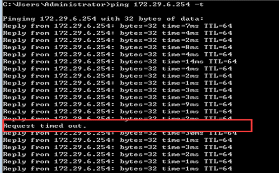
(only one packet loss during roaming)
3) Use "show ac-config client detail" on AC-2 after roaming to confirm roaming state.(Roam means roaming successfully)
AC2#show ac-config client detail 54ae.2781.d498
Mac Address :54ae.2781.d498
IP Address :192.168.10.2
Wlan Id :1
Vlan Id :10
Roam State :Roam ---->roaming user
Security Attribute :Normal
Associated Ap Information:
AP Name :1414.4b65.3cf0
AP IP :192.168.20.2

Ruijie Networks – Innovation Beyond Networks
Advanced Features
3.1 Band Select
3.1.1 Understanding Band Select
Overview
The major communication band of IEEE802.11 is divided into two parts:
3.4GHz (2.4 to 2.4835 GHz), where the 802.11b/g/n band is at;
5GHz (5.15 to 5.35 and 5.725 to 5.825 GHz), where the 802.11a/n band is at.
With the popularity of WLAN, there come more and more wireless users, many of whom use dual-band STAs which can simultaneously support the 2.4G band and the 5G band. However, 802.11b/g enjoys more popularity than 802.11a so that many dual-band STAs unanimously us e the 2.4 G band, resulting in a crowded 2.4 G band and a wasted 5G band. In fact, the 5G band has a higher access capacity while the 2.4G band can only have a maximum of three non-overlapping communication channels; moreover, the 5G band is able to provide more non-overlapping communication channels, five in China, and up to 24 in North America.
Band Select uses technical means to guide the dual-band STAs to be connected to the 5G band which has higher access capacity so as to reduce the pressure on the 2.4G band and enhance the user experience.
Band Select workflow
Commonly, without Band Select, STAs send probe frames (broadcast) on all the communication channels of all its supporting bands, and the probe frame contains the information such as the wireless access speed that STAs support and etc.; once APs which provide WLAN access services received the probe frame, APs will send out probe responses, providing some information of the WLAN that they provide to STAs; STAs usually aggregate all responses they receive and present a list of accessible WLANs to the users so that they could choose which WLAN to access.
The following figure shows the process of an STA detecting the accessible WLANs that provided by a dual-band AP. After the process is finished, the STA would detect two BSSIDs with two bands belonging to the same WLAN, but the user is unable to discern between them since their SSIDs are the same. If the user selects this WLAN for access, then the choice of two bands depends on the user's wireless driver and it is an uncontrollable factor for both the user and the AP.
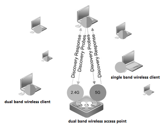
With Band Select, it guides STAs to select the 5G band in priority. As shown in below diagram, in comparison with above diagram, AP doesn't response to the 2.4G band.
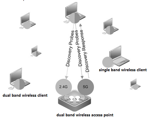
Attention:The Band Select can only work on dual-band APs; it is meaningless to use it on single-band APs.
Band Select Side Effect
Because APs do not respond to the probe request on the 2.4G band before recognizing STAs, this will lead to the fact that STAs with single-band 2.4G are unable to detect WLAN before being recognized by APs. This period of time is 20 seconds, which means that STAs with single-band 2.4G STA may not detect the accessible WLAN within 20 seconds.
Assuming the time it takes to refresh a WLAN list is 7 seconds, then the worst case is that users of STAs with single-band 2.4G are unable to see the accessible WLAN until the third time of refreshing the WLAN list; generally, if a user of STAs with single-band 2.4G STA will be able to see the WLAN after trying for a second time if the first time of refreshing the WLAN list fails to achieve that result.
3.1.2 Configuring Band Select
I. Requirements
All Ruijie AP supports "Band Select" feature except for AP110-W、AP220-E v2.x、AP220-E(C) v3.0、AP220-E(M) v2.x、AP220-I 1.x、AP220-SI v1.x、AP220-SH v 2.x、AP220-SH (C)v3.0、AP220-SH(C) v2.99、AP220-E(C) v2.99、AP620-H(C) v2.x
II. Network Topology
None
III. Configuration Steps
3. Enabling Band Select
Method 1. Enabling Band Select in all WLAN
Ruijie>enable
Ruijie#configure terminal
Ruijie(config)#band-select enable
Method 2. Enabling Band Select in a specified WLAN
Ruijie>enable
Ruijie#configure terminal
Ruijie(config)#wlan-config 520
Ruijie(config-wlan)#band-select enable
Configuring Band Select on Fat AP
Ruijie(config)#dot11 wlan 520
Ruijie(dot11-wlan-config)#band-select enable
3. For additional optional parameters, see AC& AP configuration guide, you may download it at http://www.ruijienetworks.com
IV. Verification
3. Display Band Select status, execute commands "show wlan-config cb 520". 520 is the WLAN-ID
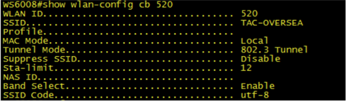
3. Display wireless clients status, execute commands "show ac-config client",
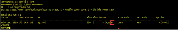
3.1.3 FAQ
3.1.3.1 How to check whether the band-select function is enabled
Run the show band-select configuration command to see whether 5G preferential access is enabled.
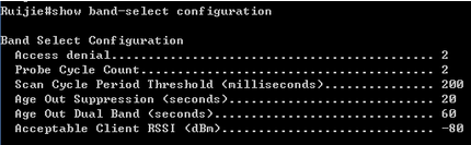
3.1.3.2 What are the influences when band-select is configured for AP?
AP does not respond to request from 2.4G frequency band before identifying STA. Thus, single-band 2.4G STA cannot detect WLAN in two second.
After AP identifies STA, dual-band STA does not respond to request of 2.4G frequency band but STA can still detect WLAN passively. In other words, some dual-band STAs can detect WLAN of 2.4G frequency band.
After AP identifies STA, dual-band STA responds to only one of N (which can be configured) authentication requests of 2.4G frequency band. Generally, if a dual-band STA detects that WLAN has the BSSID at both the 2.4G frequency band and 5G frequency band, when re-authentication request at one frequency band is not responded, it will try another frequency band. However, some dual-band STAs may always send authentication request to the same frequency band. Assuming that a dual-band STA sends M authentication requests to 2.4G frequency band before trying 5G frequency band, when N is larger than M, the STA can connect to 5G frequency band; otherwise, the STA connects to 2.4G frequency band. Whichever frequency band is used, if the dual-band STA try the 2.4G frequency band first, there is always min (M,N) requests are neglected, resulting in prolonged STA connection time. The prolonged STA connection time depend on the STA driver. For example, if STA sends authentication requests at an interval of 00 ms and four authentication requests are neglected, the STA connection time is prolonged by 400 ms.
3.1.3.3 What is the AP action when Band Select (5G preferential access) is enabled?
Before STA is identified:
AP does not respond to request of 2.4G frequency band.
AP responds to request of 5G frequency band.
After STA is identified:
Single-band 2.4G STA responds to only one of multiple requests and can connect to the WLAN.
Single-band 5G STA responds to all requests and can connect to the WLAN.
Dual-band STA does not respond to request of 2.4G frequency band but responds to 5G frequency band. It can connect to WLAN of 5G frequency band. It responds to only one of multiple requests from 2.4G frequency band and can connect to the WLAN.
3.1.3.4 Default 5G Preferential Access Parameters
| Parameter |
Default Value |
| Band Select |
Disabled |
| Acceptable lower limit of STA RSSI |
-80 dBm |
| Count of denies request of associating dual-band STA with 2.4G frequency band |
4 |
| Count of restrained STA |
2 |
| Aging scanning period of STA information |
500 ms |
| Aging time of dual-band STA information |
60s |
| Aging time of restrained STA information |
20s |
3.1.3.5 How to adjust 5G Preferential Access Parameters
Ruijie(config)# band-select acceptable-rssi value //Indicates acceptable lower limit of STA RSSI.
Ruijie(config)# band-select probe-count value //Indicates count of restrained STA.
Ruijie(config)# band-select scan-cycle period //Indicates aging scanning period of STA information.
Ruijie(config)# band-select age-out dual-band value //Indicates aging time of dual-band STA information.
Ruijie(config)# band-select age-out suppression value //Indicates aging time of restrained STA information.
3.2 AC Virtualization (VAC)
3.2.1 Implementation Preparation
3.2.1.1 Outline
The following figure shows the VAC network topology. Spare ports on the core switch (or an extra switch) can be used to establish VSL links to ACs.
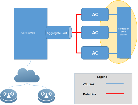
3.2.1.2 Prerequisites
l The device types of all member ACs must be the same. For example, multiple WS6108 devices can form a VAC and multiple N18K-WS devices can form a VAC. In contrast, WS6108 devices and WS6816 devices cannot form a VAC, and WS6108 devices and WS6008 devices cannot form a VAC.
l If more than two box-type ACs form a VAC, spare ports on the uplink switch (core switch in the preceding figure) or an extra switch is required to establish VSL links to ACs. The number of ports is determined based on the number of VSL links planned for each AC. If the number of ports is sufficient, it is recommended that two VSL links be planned for each AC.
![]() If two box-type ACs form a VAC, direct connections between ACs can be used as VSL links. Multiple VSL links can be planned for each AC (including box-type and card-type ACs) and serve as backups for each other.
If two box-type ACs form a VAC, direct connections between ACs can be used as VSL links. Multiple VSL links can be planned for each AC (including box-type and card-type ACs) and serve as backups for each other.
l The ports on the switch used to establish VSL links must support giant frame forwarding, and the layer-2 MTU is set to 9216.
l The ports used to connect to data links on the switch must support port aggregation. In addition, the load-sharing of the aggregation port is based on the source IP address or source and destination IP addresses.
![]() Currently, most low-end, middle-range, and high-end switches support giant frame forwarding and load-sharing over the aggregation port.
Currently, most low-end, middle-range, and high-end switches support giant frame forwarding and load-sharing over the aggregation port.
l Service links of box-type ACs need to be connected to the same uplink switch (core switch in the preceding figure).
l Card-type ACs need to be configured in the same subrack or the VSU formed by different subracks.
l Check the functions required by the customer. For details about supported and unsupported functions in the current VAC version, see chapter 3.2.5 "Service Deployment."
l Check whether cross-WLAN roaming in centralized forwarding mode is required. This function is not supported currently. Communicate with the customer about this function in advance.
3.2.2 Fast Implementation
3.2.2.1 Preparations
Before implementation, make the following preparations:
3. Plan IP addresses of ACs. A VAC is regarded as an AC and only one CAPWAP control IP address is required.
3. Compared with a standalone AC, a VAC has VSL links. Plan the ports on the switch to connect VSL links and data links.
3. If the deployed environment is reconstructed, wireless configurations on multiple ACs, including WLAN, AP group, and AP configurations, need to be combined.
3. VAC configurations and standalone AC configurations cannot be multiplexed. It is recommended that after ACs be combined to form a VAC, perform configuration again. Upon mode switching, the VAC will store standalone AC configurations. It is recommended that the standalone AC configurations be manually backed up.
Note: If a wireless network is newly deployed or the live wireless network is reconstructed, it is recommended that the VAC be configured before cable connection or the shutdown operation on corresponding ports. In this case, loops occurring before VAC configuration can be prevented.
3.2.2.2 Configuration Implementation
This section describes how to deploy a VAC, excluding wireless service deployment. The deployment differences between box-type ACs and card-type ACs are described in corresponding steps.
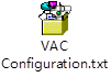
In the following configuration steps, ports 0/1 and 0/2 on the ACs are used as the service ports and ports 0/4 and 0/5 on the ACs are used as VSL ports.
3. Check the AC boot version.
M18000-WS-ED: The boot version needs to be upgraded to 1.2.10 or later.
![]() The boot version needs to be upgraded because the three rear ports on the M18000-WS-ED card are in the UP state during startup. As a result, when the M18000-WS-ED card connects to the uplink switch, traffic will be forwarded to this AC at an earlier time, resulting in packet loss. By default, the two front ports on the M18000-WS-ED card are in the DOWN state. If the two front ports are used as the service ports, the boot version does not need to be upgraded.
The boot version needs to be upgraded because the three rear ports on the M18000-WS-ED card are in the UP state during startup. As a result, when the M18000-WS-ED card connects to the uplink switch, traffic will be forwarded to this AC at an earlier time, resulting in packet loss. By default, the two front ports on the M18000-WS-ED card are in the DOWN state. If the two front ports are used as the service ports, the boot version does not need to be upgraded.
3. Upgrade the AC version to B9.
Run the upgrade download tftp command to upgrade the AC versions to a version that supports VAC (that is, B9 or later).
3. Perform VAC configuration on the ACs.
VAC configurations and standalone AC configurations are not multiplexed. Before VAC deployment, export and save standalone AC configurations. After the VAC is deployed, import the standalone AC configurations. (Before the import, modify port-related configurations. For example, the original te0/1 port is a service port, to cut configurations of the te0/1 port over to the aggregation port, add the te1/0/1 port to the aggregation port first. If the wireless-related configurations on each AC are different, the wireless-related configurations need to be integrated before being imported.)
Configurations on the first AC:
Ruijie>enable AC(config)#virtual-ac domain 100 # The domain ID is a digit. The same domain ID must be configured for each AC.
AC(config-vac-domain)#device 1 # Specify the device ID of the AC.
AC(config-vac-domain)#device 1 priority 200 # A higher priority indicates a higher probability of being selected as the active AC.
AC(config-vac-domain)#device 1 description switch1-slot3 # Define description to facilitate AC location query.
AC(config-vac-domain)#exit
AC(config)# vac-port
AC(config-vac-port)#port-member interface gigabitEthernet 0/4 # Specify VSL ports. On the WS card, specify TE ports as VSL ports.
AC(config-vac-port)#port-member interface gigabitEthernet 0/5
Configurations on the second AC:
AC(config)#virtual-ac domain 100
AC(config-vac-domain)#device 2 # Specify the device ID of the AC.
AC(config-vac-domain)#device 2 priority 100
AC(config-vac-domain)#device 2 description switch1-slot4
AC(config-vac-domain)#exit
AC(config)# vac-port
AC(config-vac-port)#port-member interface gigabitEthernet 0/4
AC(config-vac-port)#port-member interface gigabitEthernet 0/5
Configurations on other ACs are similar to the preceding ones. Specify the device ID and VSL ports.
![]() The domain ID is used to identify a VAC, which ranges from 1 to 255. ACs within the same VAC must be specified with the same domain ID. The device ID is used to identify an AC within a VAC. The device IDs of ACs within one VAC are numbered by 1, 2, 3, 4, and 5. The AC priority is used for active AC selection during VAC startup. The AC with the highest priority is selected as the active AC. In normal cases, for ease of identifying the active and standby ACs, device 1 is configured with the highest priority and device 2 is configured with the second highest priority.
The domain ID is used to identify a VAC, which ranges from 1 to 255. ACs within the same VAC must be specified with the same domain ID. The device ID is used to identify an AC within a VAC. The device IDs of ACs within one VAC are numbered by 1, 2, 3, 4, and 5. The AC priority is used for active AC selection during VAC startup. The AC with the highest priority is selected as the active AC. In normal cases, for ease of identifying the active and standby ACs, device 1 is configured with the highest priority and device 2 is configured with the second highest priority.
3. Configure the aggregation port on the uplink switch.
Service ports on ACs used to connect to the uplink switch need to be added to the aggregation port, and the load-sharing of the aggregation port is based on the source and destination IP addresses.
The uplink switch may not be provided by Ruijie, and therefore, needs to be configured based on the actual commands.
ruijie (config)#interface aggregateport 1 # The aggregation port ID is configured based on the actual switch condition.
ruijie (config-if-AggregatePort 1) # switchport mode trunk # The aggregation port is configured based on the actual network deployment requirements.
ruijie (config-if-AggregatePort 1) #exit
ruijie (config)#interface gigabitEthernet 0/1
ruijie(config-if- GigabitEthernet 0/1)#port-group 1 # Add service ports to the aggregation port.
ruijie (config-if- GigabitEthernet 0/1)#interface gigabitEthernet 0/2
ruijie(config-if- GigabitEthernet 0/2)#port-group 1
ruijie(config-if- GigabitEthernet 0/2)#exit # Add all service ports on the switch to the aggregation port using the same method.
ruijie (config)#aggregateport load-balance src-dst-ip # (Mandatory) Configure the load-sharing policy.
![]() If a port on the M18000-WS-ED card is not used as the service port or VSL port, it is recommended that unused internal ports on the 18K are shut down.
If a port on the M18000-WS-ED card is not used as the service port or VSL port, it is recommended that unused internal ports on the 18K are shut down.
3. Set the MTU value of the VSL port on the uplink switch to 9216 and configure an independent VLAN for the VSL ports. (The MTU does not need to be configured on ACs.)
ruijie(config-if-xxx)#mtu 9216
ruijie(config-if-xxx)#switchport access vlan 2024 # Obtain an unused VLAN based on actual conditions.
![]() The VSL ports of all member ACs must belong to the same layer-2 LAN and be configured with the same VLAN. It is recommended that non-VSL ports be removed from the VLAN, that is, an independent VLAN be planned only for VSL links.
The VSL ports of all member ACs must belong to the same layer-2 LAN and be configured with the same VLAN. It is recommended that non-VSL ports be removed from the VLAN, that is, an independent VLAN be planned only for VSL links.
3. Switch ACs to the VAC mode.
For box-type ACs, connect VSL ports on the ACs to VSL ports on the uplink switch. Then, switch the ACs to the VAC mode.
AC#write # Before restarting the VAC, save the VAC configurations.
AC#device convert mode virtual
Convert mode will backup and delete config file, and reload the switch. Are you sure to continue[yes/no]:yes
Do you want to recover config file from backup file in virtual mode (press 'ctrl + c' to cancel) [yes/no]:yes
![]() Configurations in independent mode and VAC mode cannot be multiplexed. After ACs are switched to the VAC mode, there is no AC configuration. The standalone AC configurations are backed up. The back files are standalone.text and ap-standalone.text.Wireless configurations of the VAC needs to be configured after the ACs are switched to the VAC mode.
Configurations in independent mode and VAC mode cannot be multiplexed. After ACs are switched to the VAC mode, there is no AC configuration. The standalone AC configurations are backed up. The back files are standalone.text and ap-standalone.text.Wireless configurations of the VAC needs to be configured after the ACs are switched to the VAC mode.
3. Configure service ports on the active AC.
After the ACs are started, run the show virtual-ac command to query member ACs of the VAC. After the ACs form a VAC normally, service ports on the active AC can be configured and added to the aggregation port.
AC(config)#interface aggregateport 1
AC(config-if-AggregatePort 1)#switchport mode trunk # Configure the aggregation port based on actual conditions.
AC(config-if-AggregatePort 1)#exit
AC(config)#interface gigabitEthernet 1/0/1 # On the M18K-WS-ED card, the service ports are TE ports.
AC(config-if-GigabitEthernet 1/0/1)#port-group 1
AC(config-if-GigabitEthernet 1/0/1)# interface gigabitEthernet 1/0/2
AC(config-if-GigabitEthernet 1/0/2)# port-group 1 # 同样的方法将其他口加入聚合口# Add other ports to the aggregation port using the same method.
After service ports are configured, connect service ports on box-type ACs to service ports on the uplink switch.
In this case, the VAC environment is set up.
3.2.2.3 Acceptance
show virtual-ac
Query the device ID, priority, and role information about each AC. If an AC is not displayed, the AC is not added to the VAC.
Device_id Domain_id Priority Position Status Role Description
-------------------------------------------------------------------------------------------
1(1) 90(90) 100(100) LOCAL OK ACTIVE switch1-slot3
2(2) 90(90) 90(90) REMOTE OK STANDBY switch1-slot4
4(4) 90(90) 50(50) REMOTE OK CANDIDATE switch1-slot5
show virtual-ac topology
Query the role and MAC address of each AC. (The MAC address is not the actually used MAC address.)
Switch[1]: ACTIVE, MAC: 5869.6c1c.43f7, Description:
Switch[2]: STANDBY, MAC: 5869.6c75.0002, Description:
Switch[4]: CANDIDATE, MAC: 003a.b64e.2500, Description:
show virtual resource
Query the CPU usage, memory usage, and flash usage of member ACs.
Device_id CPU(5s) CPU(1m) CPU(5m) Memory Flash
--------------------------------------------------
1 2.80% 4.00% 3.10% 48% 87% (34963KB free)
2 2.40% 4.60% 3.70% 48% 95% (12111KB free)
4 10.40% 7.40% 6.00% 52% 81% (52776KB free)
show interface status
Query the port status. If the ports are normal, the VSL and service ports are in the UP state.
Interface Status Vlan Duplex Speed Type
-------------------------------- -------- ---- ------- --------- ------
GigabitEthernet 1/0/5 up Full 100M copper
GigabitEthernet 1/0/8 up 201 Full 100M copper
GigabitEthernet 2/0/5 up Full 100M copper
GigabitEthernet 2/0/8 up 201 Full 100M copper
GigabitEthernet 4/0/5 up Full 100M copper
GigabitEthernet 4/0/8 up 201 Full 100M copper
AggregatePort 2 up 201 Full 100M copper
show virtual-ac balance-info
After APs go online, use this command to query APs and STA association on ACs.
Dev ID AP Num AP License STA Num
-------- -------- ---------- ----------
1 1 1.0 0
2 3 6.0 1
4 0 0.0 0
show interface counters rate
After APs go online, use this command to query the traffic over each port. In normal cases, each service port has uplink and downlink traffic.
3.2.3 Fast Implementation in VSU Scenarios
3.2.3.1 Preparations
This section describes how to implement the VAC when multiple subracks form the VSU and WS cards in different subracks form a VAC. The following figure is used as an example. In this figure, there are two subracks and each subrack has two WS cards. The two subracks form a VSU, and the four WS cards form a VAC.
Plan the AC priorities. The ACs with the highest priority and third highest priority connect to the 18K-1 and ACs with the second highest priority and lowest priority connect to the 18K-2. This prevents the active and standby ACs connect to the same 18K.
The two internal ports in the front on the WS cards are used as service ports, and port 0/5 is used as the VSL port.
3.2.3.2 Configuration Implementation
This section describes how to deploy a VAC under the VSU, excluding wireless service deployment.
In the following configuration steps, ports 0/1 and 0/2 on the ACs are used as the service ports and port 0/5 on the ACs is used as the VSL port.
3. Check the AC boot version.
If ports 0/3, 0/4, and 0/5 are used as the service ports and the traffic interruption time during hot AC addition or removal is sensitive, perform this step. Otherwise, skip this step.
M18000-WS-ED: The boot version needs to be upgraded to 1.2.10 or later.
![]() The boot version needs to be upgraded because the three rear ports on the M18000-WS-ED card are in the UP state during startup. As a result, when the M18000-WS-ED card connects to the uplink switch, traffic will be forwarded to this AC at an earlier time, resulting in packet loss. By default, the two front ports on the M18000-WS-ED card are in the DOWN state. Therefore, it is recommended that the two front ports be used as service ports. Normal use is not affected if the boot version is not upgraded. However, packet loss of several seconds occurs during hot AC addition or removal.
The boot version needs to be upgraded because the three rear ports on the M18000-WS-ED card are in the UP state during startup. As a result, when the M18000-WS-ED card connects to the uplink switch, traffic will be forwarded to this AC at an earlier time, resulting in packet loss. By default, the two front ports on the M18000-WS-ED card are in the DOWN state. Therefore, it is recommended that the two front ports be used as service ports. Normal use is not affected if the boot version is not upgraded. However, packet loss of several seconds occurs during hot AC addition or removal.
3. Upgrade the AC version to B9.
Run the upgrade download tftp command to upgrade the AC versions to a version that supports VAC.
3. Perform VAC configuration on WS cards.
Specify the ID of the device to which each AC belongs. The device ID starts from 1. Specify VSL ports.
VAC configurations and standalone AC configurations are not multiplexed. Before VAC deployment, export and save standalone AC configurations. After the VAC is deployed, import the standalone AC configurations. (Before the import, modify port-related configurations. For example, the original te0/1 port is a service port, to cut configurations of the te0/1 port over to the aggregation port, add the te1/0/1 port to the aggregation port first. If the wireless-related configurations on each AC are different, the wireless-related configurations need to be integrated before being imported.)
Configurations on WS1:
AC(config)#virtual-ac domain 100 # The domain ID is a digit. The same domain ID must be configured for each AC.
AC(config-vac-domain)#device 1 # Specify the device ID of the AC.
AC(config-vac-domain)#device 1 priority 200 # A higher priority indicates a higher probability of being selected as the active AC.
AC(config-vac-domain)#device 1 description switch1-slot3
AC(config-vac-domain)#exit
AC(config)# vac-port
AC(config-vac-port)#port-member interface te 0/5
Configurations on the second AC:
AC(config)#virtual-ac domain 100
AC(config-vac-domain)#device 2 # Specify the device ID of the AC.
AC(config-vac-domain)#device 2 priority 190
AC(config-vac-domain)#device 2 description switch2-slot5
AC(config-vac-domain)#exit
AC(config)# vac-port
AC(config-vac-port)#port-member interface te 0/5
Configurations on other ACs are similar to the preceding ones. Specify the device ID and VSL ports.
![]() The domain ID is used to identify a VAC, which ranges from 1 to 255. ACs within the same VAC must be specified with the same domain ID. The device ID is used to identify an AC within a VAC. The device IDs of ACs within one VAC are numbered by 1, 2, 3, 4, and 5. The AC priority is used for active AC selection during VAC startup. The AC with the highest priority is selected as the active AC. In normal cases, for ease of identifying the active and standby ACs, device 1 is configured with the highest priority and device 2 is configured with the second highest priority.
The domain ID is used to identify a VAC, which ranges from 1 to 255. ACs within the same VAC must be specified with the same domain ID. The device ID is used to identify an AC within a VAC. The device IDs of ACs within one VAC are numbered by 1, 2, 3, 4, and 5. The AC priority is used for active AC selection during VAC startup. The AC with the highest priority is selected as the active AC. In normal cases, for ease of identifying the active and standby ACs, device 1 is configured with the highest priority and device 2 is configured with the second highest priority.
3. Configure the aggregation port on the 18K.
The 18K and WS card are connected through an internal port. Corresponding service ports on the 18K need to be added to the aggregation port, and the load-sharing of the aggregation port is based on the source and destination IP addresses. It is recommended to use the enhanced load-sharing policy, that is, the aggregateport load-balance enhanced command below.
18K(config)# load-balance-profile vac-load-balance-profile
18K(config-load-balance-profile)# ipv4 field src-ip dst-ip
18K (config)#interface aggregateport 1 # The aggregation port ID is configured based on the actual switch condition.
18K(config-if-AggregatePort 1)# aggregateport load-balance enhanced profile vac-load-balance-profile # Configure the load-sharing policy.
18K (config-if-AggregatePort 1) # switchport mode trunk # The aggregation port is configured based on the actual network deployment requirements.
18K (config-if-AggregatePort 1) #exit
18K (config)# interface TenGigabitEthernet 1/9/3
18K(config-if-TenGigabitEthernet 1/9/3)#port-group 1 # Add service ports to the aggregation port.
18K (config-if-TenGigabitEthernet 1/9/3)# interface TenGigabitEthernet 1/9/4
18K(config-if-TenGigabitEthernet 1/9/4)#port-group 1
18K (config-if-TenGigabitEthernet 1/9/4)# interface TenGigabitEthernet 1/9/5
18K(config-if-TenGigabitEthernet 1/9/5)#shutdown # Shut down unused internal ports.
18K (config-if-TenGigabitEthernet 1/9/5)# interface TenGigabitEthernet 1/9/6
18K(config-if-TenGigabitEthernet 1/9/6)#shutdown # Shut down unused internal ports.
18K(config-if-TenGigabitEthernet 1/9/6)#exit # Add service ports on the 18K for connecting other ACs to the aggregation port using the same method.
![]() If a port on the M18000-WS-ED card is not used as the service port or VSL port, it is recommended that unused internal ports on the 18K are shut down.
If a port on the M18000-WS-ED card is not used as the service port or VSL port, it is recommended that unused internal ports on the 18K are shut down.
3. Set the MTU value of the VSL ports on the 18K to 9216 and configure an independent VLAN for the VSL ports.
18K (config)# interface TenGigabitEthernet 1/9/7
18K(config-if-TenGigabitEthernet 1/9/7)#mtu 9216
18K(config-if-TenGigabitEthernet 1/9/7)#switchport access vlan 2024 # Obtain an unused VLAN based on actual conditions, and ensure that the obtained VLAN is different from the VLAN used by VSL ports on the 18K,.
![]() The VSL ports of all member ACs must belong to the same layer-2 LAN and be configured with the same VLAN. It is recommended that non-VSL ports be removed from the VLAN, that is, an independent VLAN be planned only for VSL links.
The VSL ports of all member ACs must belong to the same layer-2 LAN and be configured with the same VLAN. It is recommended that non-VSL ports be removed from the VLAN, that is, an independent VLAN be planned only for VSL links.
3. Switch ACs to the VAC mode.
AC#write # Before restarting the VAC, save the VAC configurations.
AC#device convert mode virtual
Convert mode will backup and delete config file, and reload the switch. Are you sure to continue[yes/no]:yes
Do you want to recover config file from backup file in virtual mode (press 'ctrl + c' to cancel) [yes/no]:yes
![]() Configurations in independent mode and VAC mode cannot be multiplexed. After ACs are switched to the VAC mode, there is no AC configuration. The standalone AC configurations are backed up. The back files are standalone.text and ap-standalone.text.Wireless configurations of the VAC needs to be configured after the ACs are switched to the VAC mode.
Configurations in independent mode and VAC mode cannot be multiplexed. After ACs are switched to the VAC mode, there is no AC configuration. The standalone AC configurations are backed up. The back files are standalone.text and ap-standalone.text.Wireless configurations of the VAC needs to be configured after the ACs are switched to the VAC mode.
3. Configure service ports on the active AC.
After the ACs are started, run the show virtual-ac command to query member ACs of the VAC. After the ACs form a VAC normally, service ports on the active AC can be configured and added to the aggregation port.
AC(config)#interface aggregateport 1
AC(config-if-AggregatePort 1)#switchport mode trunk # Configure the aggregation port based on actual conditions.
AC(config-if-AggregatePort 1)#exit
AC(config)#interface TenGigabitEthernet 1/0/1
AC(config-if- TenGigabitEthernet 1/0/1)#port-group 1
AC(config-if- TenGigabitEthernet 1/0/1)# interface TenGigabitEthernet 1/0/2
AC(config-if- TenGigabitEthernet 1/0/2)# port-group 1 # Add other ports to the aggregation port using the same method.
![]() For M8600E-WS-ED model, need to configure dynamic aggregation port(LACP) to prevent the delay of aggregation port member failure in static mode.
For M8600E-WS-ED model, need to configure dynamic aggregation port(LACP) to prevent the delay of aggregation port member failure in static mode.
AC
AC (config-if-GigabitEthernet 1/0/1)# port-group 1 mode active
AC (config-if-GigabitEthernet 1/0/1)# lacp short-timeout
AC (config-if-GigabitEthernet 2/0/1)# port-group 1 mode active
AC (config-if-GigabitEthernet 2/0/1)# lacp short-timeout
SWITCH
WS (config-if-GigabitEthernet 0/10)# port-group 1 mode active
WS (config-if-GigabitEthernet 0/10)# lacp short-timeout
WS (config-if-GigabitEthernet 0/10)# exit
WS (config)# interface gigabitEthernet 0/11
WS (config-if-GigabitEthernet 0/11)# port-group 1 mode active
WS (config-if-GigabitEthernet 0/11)# lacp short-timeout
3. Enable the standby AC preemption function on the active AC.
Ruijie>enable AC(config)#virtual-ac domain 100
AC(config-vac-domain)# slave preemptive enable # Enable the standby AC preemption function.
In this case, the VAC environment is set up. Read chapters 3.2.5 "Service Deployment" and 错误!未找到引用源。 "Key Configuration Check" to learn about wireless service deployment.
3.2.3.3 Acceptance
Same as that in section 3.2.2.3 "Acceptance."
3.2.4 Capacity Expansion Implementation
3.2.4.1 Preparations
Check the maximum number of member ACs supported in a VAC.
| AC Model |
Number of Member ACs |
| WS5708/M8600-WS/M12000-WS |
VAC is not supported. |
| M18000-WS-ED/M8600E-WS-ED |
8 |
| WS6008 |
4 |
| WS6108 |
4 |
| WS6812 |
8 |
| WS6816 |
8 |
Upgrade the version of new ACs to the same version as the current VAC.
3.2.4.2 Configuration Implementation
If WS cards are used, the switch in the following steps is the 18K.The following describes how to add an AC to a VAC.
3. Add service ports on the switch to the aggregation port.
ruijie (config)#interface gigabitEthernet 0/1 # Add service ports to the aggregation port based on actual conditions.
ruijie(config-if- GigabitEthernet 0/1)#port-group 1 # Configure the aggregation port ID based on actual conditions.
ruijie (config-if- GigabitEthernet 0/1)#interface gigabitEthernet 0/2
ruijie(config-if- GigabitEthernet 0/2)#port-group 1
3. Configure VSL ports on the switch to connect to ACs.
ruijie(config-if-xxx)#mtu 9216
ruijie(config-if-xxx)#switchport access vlan 2024 # Obtain an unused VLAN based on actual conditions.
3. Perform VAC configuration on ACs.
AC(config)#virtual-ac domain 100 # The domain ID must be the same as that of the current VAC.
AC(config-vac-domain)#device 3 # The device ID is an ID not used by the current VAC.
AC(config-vac-domain)#device 3 priority 80
AC(config-vac-domain)#exit
AC(config)# vac-port
AC(config-vac-port)#port-member interface gigabitEthernet 0/4 # Specify VSL ports. On the WS card, specify TE ports as VSL ports.
AC(config-vac-port)#port-member interface gigabitEthernet 0/5
3. Switch the ACs to the VAC mode.
For box-type ACs, connect VSL ports on the ACs to VSL ports on the uplink switch. Then, switch the ACs to the VAC mode.
AC#write # Before restarting the VAC, save the VAC configurations.
AC#device convert mode virtual
Convert mode will backup and delete config file, and reload the switch. Are you sure to continue[yes/no]:yes
Do you want to recover config file from backup file in virtual mode (press 'ctrl + c' to cancel) [yes/no]:yes
In this case, the new AC is automatically added to the VAC after being restarted.
3.2.4.3 Acceptance
Run the show virtual-ac command on the active AC to check whether the new AC is added to the VAC. In normal case, when the new AC is started up, the active AC can view the new AC, and the corresponding device ID can be queried from the show virtual-ac command output.
show virtual-ac
Device_id Domain_id Priority Position Status Role Description
-------------------------------------------------------------------------------------------
1(1) 90(90) 100(100) LOCAL OK ACTIVE
2(2) 90(90) 90(90) REMOTE OK STANDBY
4(4) 90(90) 50(50) REMOTE OK CANDIDATE
show interface status
Query the port status. In normal cases, the service port is DOWN and the VSL port is UP on the new AC. After all table entries are synchronized to the new AC, the service port is changed to the UP state and starts to work.
Interface Status Vlan Duplex Speed Type
-------------------------------- -------- ---- ------- --------- ------
GigabitEthernet 1/0/1 up 1 Full 100M copper
GigabitEthernet 1/0/2 up 1 Full 100M copper
GigabitEthernet 1/0/3 down 1 Unknown Unknown copper
GigabitEthernet 1/0/4 down 1 Unknown Unknown copper
GigabitEthernet 1/0/5 up Full 100M copper
GigabitEthernet 1/0/6 down 1 Unknown Unknown copper
GigabitEthernet 1/0/7 down 1 Unknown Unknown copper
GigabitEthernet 1/0/8 down 1 Unknown Unknown copper
GigabitEthernet 2/0/1 up 1 Full 100M copper
GigabitEthernet 2/0/2 up 1 Full 100M copper
GigabitEthernet 2/0/3 down 1 Unknown Unknown copper
GigabitEthernet 2/0/4 down 1 Unknown Unknown copper
GigabitEthernet 2/0/5 up Full 100M copper
GigabitEthernet 2/0/6 down 1 Unknown Unknown copper
GigabitEthernet 2/0/7 down 1 Unknown Unknown copper
GigabitEthernet 2/0/8 down 1 Unknown Unknown copper
GigabitEthernet 4/0/1 up 1 Full 100M copper
GigabitEthernet 4/0/2 up 1 Full 100M copper
GigabitEthernet 4/0/3 down 1 Unknown Unknown copper
GigabitEthernet 4/0/4 down 1 Unknown Unknown copper
GigabitEthernet 4/0/5 up Full 100M copper
GigabitEthernet 4/0/6 down 1 Unknown Unknown copper
GigabitEthernet 4/0/7 down 1 Unknown Unknown copper
GigabitEthernet 4/0/8 down 1 Unknown Unknown copper
After the new AC starts and table entries are synchronized, the service port is changed to the UP state and a large number of APs are migrated to the AC, which can be confirmed through syslogs.
3.2.5 Service Deployment
3.2.5.1 Services Not Supporting VAC
Currently, AC virtualization does not support the following functions:
IPv6
NAT (NAT enabled on ACs)
Wi-Fi connection via WeChat
Web first-generation authentication and authentication for MCP/WMC interworking
GSN
Hot backup between VACs
Roaming between 2 or more VAC instances
Zone control function
Intra-frequency networking
RPCAP(Remote Packet Capture system)
RF ping
RRM
RIPT
Proactive AP load-sharing on ACs is not supported, and AP load-sharing depends on load-sharing of the aggregation port on the uplink switch. When the AC and AP are deployed across networks of different ISPs (through NAT), the source IP addresses of APs may be the same, and APs with the same source IP address will be connected to the same member AC, resulting in a poor AP load-sharing effect.
Port mirroring is not supported. If port mirroring is enabled, packets are transmitted over the VSL ports, which may result in VAC splitting.
3.2.5.2 Configuration Operations
AC virtualization can be configured only on the active AC. If the AC connected through the serial port is not the active AC, run the session master command to connect to the active AC for configuration. You can run the show run command on ACs to query the AC configurations.
On a non-active AC, the IP address configurations of ports cannot be queried by running the show running-config command.
Note AP offline configurations. For example, if the 11acsupport enable radio 2 command is configured for an AP in offline mode and the AP goes online through the standby AC, the AP configuration is changed to no 11acsupport enable radio 2 on the standby AC as the AP does not support 802.11ac. On the active AC, the AP configuration is still 1acsupport enable radio 2. A large number of other similar commands are changed when an AP goes online. Currently, the configuration change is presented only on the AC associated with the AP. This situation does not affect normal AP usage.
3.2.5.3 AP Management Operations
When a satellite AP is associated with a VAC, the satellite AP information possibly cannot be queried from the VAC by running the show ap-sr summary command.
When the show ap-config command is run on the VAC, only the license information about the local AC can be queried. The license information of the VAC cannot be queried.
![]() The preceding two points are known issues in the current version and will be rectified in the next version.
The preceding two points are known issues in the current version and will be rectified in the next version.
3.2.5.4 STA Management Operations
Currently, the VAC does not support the zone control function. The zone control function does not take effect to the whole VAC.
Currently, the VAC does not support cross-WLAN roaming in centralized forwarding mode. Cross-WLAN indicates that two WLANs are configured, and the two WLANs have the same SSID and encrypted authentication mode. Different APs map to different VLANs, and STAs roam between the two WLANs. Communicate with the customer in advance about this situation before network deployment or reconstruction.
3.2.5.5 AC/AP Upgrade Operations
3.2.5.5.1.1 AC Upgrade
When the software version of a VAC is upgraded, all member ACs within the VAC will be upgraded at the same time. If the flash memory of one member AC is insufficient or the AC cannot be upgraded due to other causes, the VAC upgrade fails. When a new member AC is added and the software version of the member AC is different from the software version of other member ACs in the VAC, the member AC is not automatically upgraded and cannot be added to the VAC. The new member AC can be added to the VAC only after the administrator upgrades the software version of the new member AC independently.
You can run the show virtual-ac resource command on ACs to check whether the flash memory is sufficient. If a .bin.up.tmp file (upgrade file for the previous AC version upgrade) exists in the flash memory, the file can be deleted.
Device_id CPU(5s) CPU(1m) CPU(5m) Memory Flash
--------------------------------------------------
1 2.50% 3.60% 2.80% 48% 87% (34922KB free)
2 3.80% 4.80% 3.50% 48% 95% (12140KB free)
3 4.90% 6.80% 5.40% 52% 81% (50823KB free)
3.2.5.5.1.2 AP Upgrade
The AP upgrade file needs to be synchronized to member ACs. If the flash memory of a member AC is insufficient, the upgrade file synchronization fails. In this case, the AP associated with that member AC will not be automatically upgraded.
You can run the show ac-config active-file status command to check whether file transfer fails. If the file transfer fails, run the dir dev2_flash and delete dev2_flash:xxx commands in privileged EXEC mode to delete unused files on the device and run the active-bin-file command again after sufficient space is provided.
show ac-config active-file status
Check whether upgrade file synchronization to an AC is abnormal.
File Name Software number Device File Tx Description
---------------------------------- -------------------- ------ ------- -----------
ap110.bin M02211607122016 1 100 % Success
ap110.bin M02211607122016 3 100 % Success
am5528-b9-0705.bin M06162807052016 2 0 % Flash space not enough
AC# dir dev2_flash:
Query the flash memory information of an AC with a specified device ID.
-rwxrwxrwx 1 anonymous ftp 130973 Jul 25 17:16 syslog_3.txt
drwxrwxrwx 2 anonymous ftp 160 Dec 04 2015 dev
drwxrwxrwx 2 anonymous ftp 160 Dec 04 2015 rep
drwxrwxrwx 3 anonymous ftp 224 Dec 04 2015 var
-rw-r--r-- 1 anonymous ftp 25017 Aug 23 10:21 virtual_switch.text
-rwxrwxrwx 1 anonymous ftp 15254656 Jun 07 10:54 ap320-rgos10.bin
-rwxrwxrwx 1 anonymous ftp 1329 Jun 06 19:56 getnext_mib_register.text
-rwxrwxrwx 1 anonymous ftp 126 Aug 23 16:24 config_vac.dat
-rwxrwxrwx 1 anonymous ftp 23643197 May 19 17:39 ap320-b9.bin
-rwxr-xr-x 1 anonymous ftp 83091668 Aug 23 14:48 ws5708-b9p2.bin.up.tmp
-rwxrwxrwx 1 anonymous ftp 130989 Jul 25 17:16 syslog_10.txt
-rwxrwxrwx 1 anonymous ftp 131009 Jul 25 17:16 syslog_11.txt
-rwxrwxrwx 1 anonymous ftp 887 Dec 04 2015 httpd_key.pem
-rwxrwxrwx 1 anonymous ftp 2811 Aug 15 17:44 standalone.text
-rwxrwxrwx 1 anonymous ftp 4997 Mar 22 18:02 card_ws5708_10.xml
-rwxrwxrwx 1 anonymous ftp 130968 Jul 25 17:16 syslog_1.txt
-rwxrwxrwx 1 anonymous ftp 130915 Jul 25 17:16 syslog_2.txt
66 files, 11 directories
281,903,104 bytes data total (68,780,032 bytes free)
536,870,912 bytes flash total (68,780,032 bytes free)
For example, the ap320-rgos10.bin file is useless. Delete the file and activate the upgrade file again.
AC# delete dev2_flash:ap320-rgos10.bin
AC#configure
AC(config)#ac-controller
AC(config-ac)#active-bin-file am5528-b9-0705.bin
![]() Use the ap-image auto-upgrade command for AP upgrades. After this command is run, an upgrade file is automatically provided for the AP for an upgrade based on the AP model. The ap-serial command is executed after the active-bin-file command. If the no active-bin-file command is executed when the upgrade file is synchronized to the standby AC, the upgrade file may be activated on the active AC but not activated on the standby AC. In this case, run the show ac-config active-file status command to query the upgrade file activation status on ACs. If inconsistency occurs, activate the upgrade file on the active AC again.
Use the ap-image auto-upgrade command for AP upgrades. After this command is run, an upgrade file is automatically provided for the AP for an upgrade based on the AP model. The ap-serial command is executed after the active-bin-file command. If the no active-bin-file command is executed when the upgrade file is synchronized to the standby AC, the upgrade file may be activated on the active AC but not activated on the standby AC. In this case, run the show ac-config active-file status command to query the upgrade file activation status on ACs. If inconsistency occurs, activate the upgrade file on the active AC again.
![]() If an AC sends the upgrade file to an AP, but the no active-bin-file command is configured, the upgrade file delivery will be stopped. APs that do not receive the upgrade file completely will be restarted after a period of time. After the APs are restarted, the version before the upgrade is used.
If an AC sends the upgrade file to an AP, but the no active-bin-file command is configured, the upgrade file delivery will be stopped. APs that do not receive the upgrade file completely will be restarted after a period of time. After the APs are restarted, the version before the upgrade is used.
3.2.5.6 SNMP Management Operations
In AC virtualization, AC information needs to be collected from all member ACs when SNMP is used and the return speed may be slow. In this case, the SNMP cache function is added to cache SNMP data on member ACs to the active AC periodically to improve the table reading efficiency.
Note that the host updates the cache every 5 minutes by default after the SNMP cache function is configured. Therefore, when the server delivers the SNMP-GET operation, the data obtained may be generated in the previous 5 minutes. The update period can be adjusted based on the frequency of performing the GET operation by the EMS software.
snmp-server cache update-timer # Configure the cache update interval. A short interval will result in high CPU usage and a long interval may result in a delayed update.
snmp-server cache enable # Enable the SNMP cache function.
snmp-server cache oid 1.3.6.1.2.1.145.1.2.2.1
snmp-server cache oid 1.3.6.1.2.1.145.1.2.3.1
snmp-server cache oid 1.3.6.1.2.1.145.1.2.6.1
snmp-server cache oid 1.3.6.1.2.1.145.1.2.7.1
snmp-server cache oid 1.3.6.1.4.1.4881.1.1.10.2.1.1.39.1
snmp-server cache oid 1.3.6.1.4.1.4881.1.1.10.2.1.1.48.1
snmp-server cache oid 1.3.6.1.4.1.4881.1.1.10.2.1.1.49.1
snmp-server cache oid 1.3.6.1.4.1.4881.1.1.10.2.10.1.12.1
snmp-server cache oid 1.3.6.1.4.1.4881.1.1.10.2.10.1.13.1
snmp-server cache oid 1.3.6.1.4.1.4881.1.1.10.2.19.1.1.10.1
snmp-server cache oid 1.3.6.1.4.1.4881.1.1.10.2.19.1.1.11.1
snmp-server cache oid 1.3.6.1.4.1.4881.1.1.10.2.35.1.3.1
snmp-server cache oid 1.3.6.1.4.1.4881.1.1.10.2.36.1.3.1
snmp-server cache oid 1.3.6.1.4.1.4881.1.1.10.2.40.1.1.1
snmp-server cache oid 1.3.6.1.4.1.4881.1.1.10.2.40.1.5.1
snmp-server cache oid 1.3.6.1.4.1.4881.1.1.10.2.56.2.1.1.1
snmp-server cache oid 1.3.6.1.4.1.4881.1.1.10.2.56.2.1.2.1
snmp-server cache oid 1.3.6.1.4.1.4881.1.1.10.2.56.2.1.3.1
snmp-server cache oid 1.3.6.1.4.1.4881.1.1.10.2.56.2.1.6.1
snmp-server cache oid 1.3.6.1.4.1.4881.1.1.10.2.56.2.1.7.1
snmp-server cache oid 1.3.6.1.4.1.4881.1.1.10.2.56.5.1.1.1
snmp-server cache oid 1.3.6.1.4.1.4881.1.1.10.2.64.1.1.38.1
snmp-server cache oid 1.3.6.1.4.1.4881.1.1.10.2.64.1.1.39.1
snmp-server cache oid 1.3.6.1.4.1.4881.1.1.10.2.73.1.3.1.1.1
snmp-server cache oid 1.3.6.1.4.1.4881.1.1.10.2.81.1.3.1.1
snmp-server cache oid 1.3.6.1.4.1.4881.1.1.10.2.81.10.2.1.1
snmp-server cache oid 1.3.6.1.4.1.4881.1.1.10.2.81.10.4.1.1
snmp-server cache oid 1.3.6.1.4.1.4881.1.1.10.2.81.10.5.1.1
snmp-server cache oid 1.3.6.1.4.1.4881.1.1.10.2.81.10.5.2.1
snmp-server cache oid 1.3.6.1.4.1.4881.1.1.10.2.81.10.7.1.1
snmp-server cache oid 1.3.6.1.4.1.4881.1.1.10.2.81.14.2.1
snmp-server cache oid 1.3.6.1.4.1.4881.1.1.10.2.81.15.1.1
snmp-server cache oid 1.3.6.1.4.1.4881.1.1.10.2.81.16.1.1
snmp-server cache oid 1.3.6.1.4.1.4881.1.1.10.2.81.16.2.1
snmp-server cache oid 1.3.6.1.4.1.4881.1.1.10.2.81.2.1.1.1
snmp-server cache oid 1.3.6.1.4.1.4881.1.1.10.2.81.2.3.1.1
snmp-server cache oid 1.3.6.1.4.1.4881.1.1.10.2.81.3.1.1
snmp-server cache oid 1.3.6.1.4.1.4881.1.1.10.2.81.6.1.1
![]() The cache update period can be configured based on the software query period of the EMS server (SNC, RILL, or the like).
The cache update period can be configured based on the software query period of the EMS server (SNC, RILL, or the like).
3.2.5.7 SNC Configuration Operations
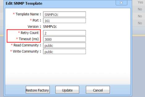
When the SNC is used to manage the VAC, VSL links between ACs will not be displayed on the device details page.
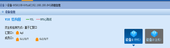
3.2.5.8 Dual-Active Detection
When box-type ACs form a VAC, it is recommended that the dual-active detection (DAD) function be enabled. If two box-type ACs form a VAC, it is recommended that BFD be used. The direct-connected links are used for detection. If more than two ACs are used, it is recommended that the aggregation port be used for detection. To use aggregation port detection, the switch must support DAD forwarding.
For example, use ports 0/3 on two ACs for direct connection and configure the BFD. The configuration steps are as follows:
AC(config)#interface gigabitEthernet 1/0/3
AC(config-if-GigabitEthernet 1/0/3)#no switchport
AC(config-if-GigabitEthernet 1/0/3)# interface gigabitEthernet 2/0/3
AC(config-if-GigabitEthernet 2/0/3)#no switchport
AC(config-if-GigabitEthernet 2/0/3)#exit
AC(config)#virtual-ac domain 100 # domain id # Domain ID indicates the ID specified during VAC deployment.
AC(config-vac-domain)# dual-active detection bfd
AC(config-vac-domain)# dual-active bfd interface GigabitEthernet 1/0/3
AC(config-vac-domain)# dual-active bfd interface GigabitEthernet 2/0/3
Check whether the BFD detection port is in the UP state.
AC(config)# show virtual-ac dual-active bfd
BFD dual-active detection enabled: Yes
BFD dual-active interface configured:
GigabitEthernet 1/0/3: UP
GigabitEthernet 2/0/3: UP
Configure DAD for the aggregation port. The configuration steps are as follows:
AC(config)#virtual-ac domain 100 # domain id # Domain ID indicates the ID specified during VAC deployment.
AC(config-vac-domain)# dual-active detection aggregateport
AC(config-vac-domain)# dual-active interface aggregateport 1
Ruijie(config)# interface aggregateport 1 # Enable DAD forwarding on the uplink switch.
Ruijie(config-if-AggregatePort 1)#dad relay enable
Check whether the DAD port on the aggregation port is in the UP state.
show virtual-ac dual-active aggregateport
Aggregateport dual-active detection enabled: Yes
Aggregateport dual-active interface configured:
AggregatePort 1: DOWN
GigabitEthernet 1/0/8: DOWN
GigabitEthernet 2/0/8: DOWN
3.2.6 Key Configuration Check
l Check whether the MTU of 9216 is configured for VSL ports on the switch.
l Check whether an independent VLAN is configured for VSL links on the switch.
l Check whether the load-sharing policy based on the source and destination IP addresses is configured on the switch.
l Check whether the AC versions are the same, which can be queried by running the show version command.
l If SNMP is used, check whether the SNMP cache function is enabled and check whether the OID needs to be added to the cache.
3.2.7 FAQ
3.2.7.1 Can Multiple ACs in Different WANs Form a VAC?
3.2.7.2 Can ACs of Different Models Form a VAC?
3.2.7.3 Can Two VACs Work in Hot Backup Mode?
Currently, VACs cannot work in hot backup mode.
3.2.7.4 Can VSL Links Be Set Up by Directly Connecting ACs?
If only two ACs form a VAC, the VSL links can be set up by directly connecting the two ACs. If more than two ACs form a VAC, the ACs need to connect to the switch to form the star topology. Multiple ACs cannot be connected in serial mode or ring mode using VSL links.
3.2.7.5 Why VSL Ports Are in the DOWN State When a Member AC Is Added?
When a member AC is added, the show virtual-ac command output shows that the member AC is added. However, when the show interface status command is run, the VSL port status is DOWN. When an AC is added, table entries and wireless configurations need to be synchronized to the AC. VSL ports are in the UP state only after the table entries and wireless configurations are synchronized. This process may take several minutes or longer.
3.2.7.6 How to Solve the Problem of AP Load Imbalance When Switches Form the VSU mode and ACs Form a VAC?
Two subracks form the VSU, and WS cards are inserted to the subracks. By default, local forwarding is preferred on switches forming the VSU, that is, CAPWAP packets of APs will be forwarded to the WS card on the subrack that they pass through, and these APs are associated with the WS card on this subrack. CAPWAP packets of these APs will not be forwarded to the other subrack.
It is recommended that the switches forming the VSU also use the aggregation port, and the loading-sharing of the aggregation port is based on the source and destination IP addresses. In this case, packets of APs will be forwarded to the two subracks in load-sharing mode on the switch, and packets on the two subracks are forwarded to the WS cards in load-sharing mode.
3.2.7.7 How to Add ACs of Different Versions to a VAC?
Currently, ACs of different versions can form a VAC. When this situation occurs, it is recommended that ACs of earlier versions be separately upgraded and then added to the VAC. In the current version, upgrading partial ACs is not supported.
3.2.7.8 Port Mirroring Is Not Supported
When port mirroring is enabled, if the mirroring packets are forwarded to another AC through the VSL link, VAC splitting may occur. If the VAC is split and then combined, partial ACs will restart, affecting services on the network.
3.2.7.9 How Long Does Standby AC Preemption Take?
The standby AC preemption function is used when switches form the VSU and ACs form a VAC, to prevent the active and standby ACs residing in the same subrack. If the subrack restarts, the VAC restarts. When a new AC is added to a VAC and the priority of the new AC is higher than the standby AC, the system checks whether the priority of any candidate AC is higher than that of the standby AC after 30 minutes. If the priority of a candidate AC is higher than that of a standby AC, the standby AC is restarted and an AC with the highest priority in candidate ACs is selected as the standby AC.
3.2.7.10 How Long Does AP Connection Drop Take When an AC Is Removed and the Licenses Are Insufficient?
3.2.8 Common Fault Locating
3.2.8.1 Telnet Connection to the VAC Is Suspended Occasionally and Becomes Normal After Being Reconnected
Suspension easily occurs when the show command output is large. When the Telnet connection is disconnected and re-connected, the connection becomes normal. This is because the MTU of some VSL ports on the switch is not set to 9216. Check configurations of VSL ports on the switch.
3.2.8.2 APs Cannot Go Online and DataCheckTimer Expire Is Printed
*Jun 27 15:18:52: %CAPWAP-6-PEER_NOTIFY_DOWN: Peer <100.0.0.14 : 10000 : 00d0.f822.6666> DOWN, reason <DataCheckTimer Expire>.
If the log DataCheckTimer Expire is printed for a large number of APs, the load-sharing configured on the uplink switch may not be based on the source IP address or source and destination IP addresses. As a result, CAPWAP packets of the same AP are forwarded to different ACs in load-sharing mode and the AP cannot go online. Check the load-sharing policy on the uplink switch.666666666666666666666
3.3 AC Hot-Backup
3.3.1 Understanding AC Hot-Backup
Overview
Currently, there are two ways to deploy a wireless LAN (WLAN): fit access point (AP) mode and fat AP mode. The fit AP mode has become the mainstream deployment mode. The fit AP mode involves the following wireless devices: access controllers (ACs) and APs. APs are connected with ACs. Users perform configuration on ACs, which then deliver configuration to APs. Through the collaboration protocol CAPWAP defined in RFC5415, ACs and APs can jointly provide WLAN services for users.
The protocol specifies that when a CAPWAP connection is established between an AC and APs, a CAPWAP communication tunnel will be established between the AC and each AP. The packets delivered between the AC and each AP are transmitted through the CAPWAP tunnel. As shown in Figure 1, CAPWAP tunnels are P2P unicast tunnels.
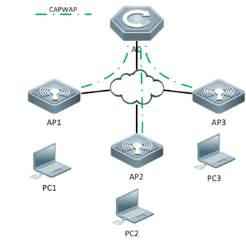
The Ruijie Network AC hot-backup function provides the millisecond-level master/slave switch over capability when the master AC fails, so that services of associated users are nearly not interrupted:
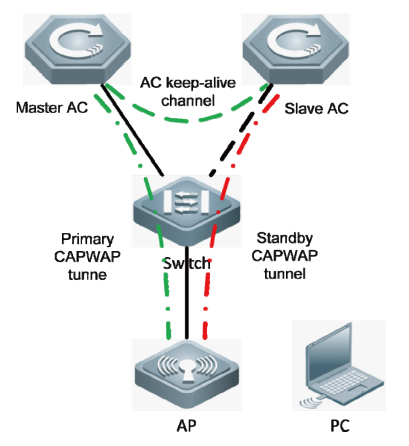
3. The master and slave roles of the two ACs are determined based on negotiation. They keep alive based on the keep-alive mechanism.
3. The AP sets up a primary CAPWAP tunnel with the master AC and sets up a standby one with the slave AC.
3. Users can access the AP through a wireless client.
3. Users can access external networks through the primary CAPWAP tunnel between the AP and the AC.
3. When the master AC fails and the slave AC detects that the keep-alive time expires, the slave AC notifies the AP of the failure.
3. The standby CAPWAP tunnel is activated and the slave AC becomes the master AC.
3. User services are restored after the standby CAPWAP tunnel is activated.
3. When the original master AC recovers, it re-establishes a hot backup association with the original slave AC. The original master AC becomes the slave AC and the AP sets up a standby tunnel with the AC, so that users ‘services are nearly not interrupted.
Attentions: ACs communicate with each other through a Layer 3 keep-alive tunnel. When the hot-standby topology is designed, the link between ACs must remain accessible.
The AC hot-backup has two modes: active/standby (A/S) and active/active (A/A) mode.
3. A/S Mode
In A/S mode, the AC in the active state is the master device, and the other in the standby state is the slave device. The master AC processes all services, and transmits information about service status to the slave AC for backup, while the slave AC is responsible only for the backup. In this mode, all APs set up primary CAPWAP tunnels with the master AC, and standby tunnels with the slave AC. When the two ACs work properly, the master AC processes all services. If the master AC fails, all services are switched to the slave AC. 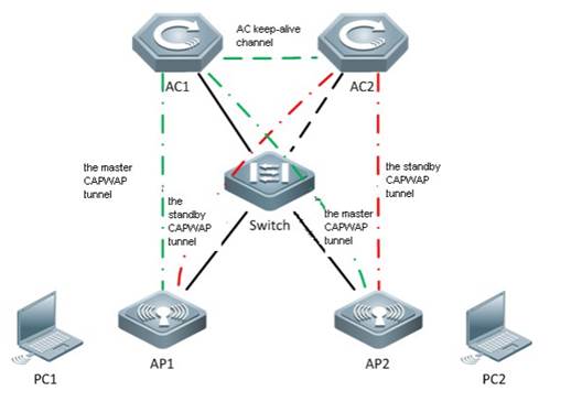
3. A/A Mode
In A/A mode, both ACs process services as the master devices and each serves as the backup of the peer AC. Assume that the two ACs are AC 1 and AC 2. In A/A mode, some APs set up primary CAPWAP tunnels with AC 1 and standby CAPWAP tunnels with AC 2, while others set up primary CAPWAP tunnels with AC 2 and standby CAPWAP tunnels with AC 1. When the two ACs work properly, they process services of the APs that set up primary CAPWAP tunnels with them. If AC 1 fails, the services of the APs are switched to standby CAPWAP tunnels and are taken over by AC 2.
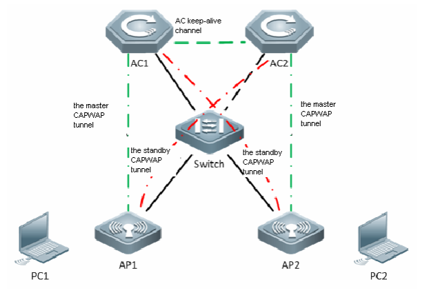
3.3.2 Configuring AC Hot-Backup
I. Requirements
Notes: The configuration of Hot AC and Backup AC should be the same. The AC Hot-Backup function will not be supported when configuring the Web-auth V1 or Iportal.
II. Network Topology
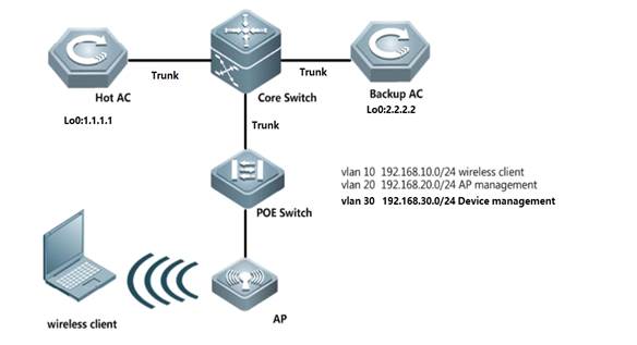
III. Configuration Steps
Configuring AC Hot-Backup
Attention:
3. In hot-backup scenario, should assign DHCP Option 138 to AP in below either ways:
ip dhcp pool AP
option 138 ip 1.1.1.1 --->1.1.1.1 is loopback port on Hot AC
or
option 138 1.1.1.1 2.2.2.2 --->2.2.2.2 is loopback port on Backup AC
3. If you want to modify configuration of "ap-group" when Hot-backup is done, suggest modify on Hot AC first, then do the same on Backup AC. When finish modification, suggest reload AP in free time.
3. Configuring routes, Hot AC and Backup AC are able to communicate with each other via Loopback port.
Core Switch:
Core(config)#ip route 1.1.1.1 255.255.255.255 192.168.30.2
Core(config)#ip route 2.2.2.2 255.255.255.255 192.168.30.3
Hot AC:
Core(config)#ip route 1.1.1.1 255.255.255.255 192.168.30.2 Hot(config)#ip route 0.0.0.0 0.0.0.0 192.168.30.1
Backup AC:
Backup(config)#ip route 0.0.0.0 0.0.0.0 192.168.30.1
3. Configuring AC Hot-backup
Solution 1: Set wireless DHCP on Core Switch, all wireless client point gateway to Core Switch (Recommend)
Hot AC:
Hot(config)#wlan-config 1 GroundFloor ----->the configuration on Hot&Backup should be the same
Hot(config)#ap-group ruijie ----->the configuration on Hot&Backup should be the same
Hot(config-ap-group)#interface-mapping 1 10 ----->the configuration on Hot&Backup should be the same , even for the sequence if you configure more than 1 interface-mapping
Hot(config-ap-group)#exit
Hot(config)# wlan hot-backup 2.2.2.2 ----->2.2.2.2 is IP address of Backup AC loopback port
Hot(config-hotbackup)# context 10 ----->the configuration on Hot&Backup should be the same
Hot(config-hotbackup-ctx)# priority level 7 ----->configure priority , the bigger number the more prior. In addtion, "7" indicates enable preempt
Hot(config-hotbackup-ctx)# ap-group ruijie
Hot(config-hotbackup)#exit
Hot(config-hotbackup)# wlan hot-backup enable ----->enable hot-backup
Note: it can also support to set up hot-backup with non-loopback port (examples below).
Ruijie#configure
Enter configuration commands, one per line. End with CNTL/Z.
Ruijie(config)#wlan hot-backup 192.168.120.100
Ruijie(config-hotbackup)#local-ip 192.168.120.110
Ruijie(config-hotbackup)#context 10
Ruijie(config-hotbackup-ctx)#exit
Ruijie(config-hotbackup)#wlan hot-backup enable
Backup AC:
Backup(config)#wlan-config 1 GroundFloor
Backup(config)#ap-group ruijie
Backup(config-ap-group)#interface-mapping 1 10
Backup(config)# exit
Backup(config)# wlan hot-backup 1.1.1.1
Backup(config-hotbackup)# context 10
Backup(config-hotbackup-ctx)# ap-group ruijie
Backup(config-hotbackup)# exit
Backup(config-hotbackup)# wlan hot-backup enable
Add AP on Hot and Backup AC (take AP mac: 0001.0000.0001 for example and assume AP is online):
Hot AC:
AC-1(config)#ap-config 0001.0000.0001 ----->AP is online
AC-1(config-ap)#ap-group ruijie
AC-1(config-ap)#ap-name ap320 ----->the AP name need to be same on Hot AC and Backup AC
Backup AC:
AC-2(config)#ap-config ap320 -----> pre-configuration, AP is offline on Backup AC
AC-2(config-ap)#ap-mac 0001.0000.0001
AC-2(config-ap)#ap-group ruijie
Solution 2: Set wireless DHCP on AC, all wireless client point gateway to AC
Core Switch:
Core(config)#ip route 192.168.10.0 255.255.255.0 192.168.30.2 --->192.168.10.0/24 is wireless user IP subnets
Core(config)#ip route 192.168.10.0 255.255.255.0 192.168.30.3
Hot AC:
Hot(config)#interface VLAN 10
Hot(config-if-VLAN 10)#ip address 192.168.10.2 255.255.255.0
Hot(config-if-VLAN 10)#vrrp 1 ip 192.168.10.1 ----->enable VRRP
Hot(config)#service dhcp
Hot(config)#ip dhcp pool sta ----->DHCP pool for wireless users
Hot(dhcp-config)#network 192.168.10.0 255.255.255.0 192.168.10.4 192.168.10.254 ----->assign IP subnets 192.168.10.0/24 to wireless users,assign IP starts from 192.168.10.4 to 192.168.10.254
Hot(dhcp-config)# dns-server 8.8.8.8
Hot(dhcp-config)# default-router 192.168.10.1
Hot(config)#ap-group ruijie
Hot(config-ap-group)#interface-mapping 1 10 ----->the configuration on Hot&Backup should be the same , even for the sequence if you configure more than 1 interface-mapping)
Hot(config-ap-group)#exit
Hot(config)#wlan hot-backup 2.2.2.2 ----->2.2.2.2 is IP address of Backup AC loopback port
Hot(config-hotbackup)# context 10 ----->the configuration on Hot&Backup should be the same
Hot(config-hotbackup-ctx)# priority level 7 ----->configure priority, the bigger number the more prior. In addtion, "7" indicates enable preempt
Hot(config-hotbackup-ctx)# ap-group ruijie
Hot(config-hotbackup-ctx)# dhcp-pool sta ----->set DHCP hot-backup. DHCP server on Backup AC will not respond when Hot AC is alive
Hot(config-hotbackup-ctx)# vrrp interface vlan 10 group 1 ----->set Gateway hot-backup. VRRP status on Backup AC will remain in "Init" when Hot AC is alive.
Hot(config-hotbackup-ctx)# exit
Hot(config-hotbackup)# wlan hot-backup enable ----->enable Hot-backup
Backup AC:
Backup(config)#interface VLAN 10
Backup(config-if-VLAN 10)#ip address 192.168.10.3 255.255.255.0
Backup(config-if-VLAN 10)# vrrp 1 ip 192.168.10.1
Backup(config)#service dhcp
Backup(config)#ip dhcp pool sta
Backup(dhcp-config)#network 192.168.10.0 255.255.255.0 192.168.10.4 192.168.10.254
Backup(dhcp-config)# dns-server 8.8.8.8
Backup(dhcp-config)# default-router 192.168.10.1
Backup(config)#ap-group ruijie
Backup(config-ap-group)#interface-mapping 1 10
Backup(config-ap-group)#exit
Backup(config)#wlan hot-backup 1.1.1.1
Backup(config-hotbackup)# context 10
Backup(config-hotbackup-ctx)# ap-group ruijie
Backup(config-hotbackup-ctx)# dhcp-pool sta
Backup(config-hotbackup-ctx)# vrrp interface vlan 10 group 1
Backup(config-hotbackup-ctx)#exit
Backup(config-hotbackup)# wlan hot-backup enable
Add AP on Hot and Backup AC (take AP mac: 0001.0000.0001 for example and assume AP is online):
Hot AC:
AC-1(config)#ap-config 0001.0000.0001 ----->AP is online
AC-1(config-ap)#ap-group ruijie
AC-1(config-ap)#ap-name ap320 ----->the AP name need to be same on Hot AC and Backup AC
Backup AC:
AC-2(config)#ap-config ap320 -----> pre-configuration, AP is offline on Backup AC
AC-2(config-ap)#ap-mac 0001.0000.0001
AC-2(config-ap)#ap-group ruijie
IV. Verification
3. Display Hot-backup status, execute commands "show wlan hot-backup". The connect state should be "CHANNEL_UP " if it works properly
Hot#show wlan hot-backup 2.2.2.2
wlan hot-backup 2.2.2.2
hot-backup : Enable
connect state : CHANNEL_UP
hello-interval: 1000
kplv-pkt : ip
work-mode : NORMAL
!
context 10
hot-backup role : PAIR-ACTIVE
hot-backup rdnd state : REALTIME-SYN
hot-backup priority : 7
ap-group : ruijie
dhcp-pool : sta
vrrp interface - group: VLAN 10 - 1
Backup#show wlan hot-backup 1.1.1.1
wlan hot-backup 1.1.1.1
hot-backup : Enable
connect state : CHANNEL_UP
hello-interval: 1000
kplv-pkt : ip
work-mode : NORMAL
!
context 10
hot-backup role : PAIR-STANDBY
hot-backup rdnd state : REALTIME-SYN
hot-backup priority : 4
ap-group : ruijie
dhcp-pool : sta
vrrp interface - group: VLAN 10 - 1
3. Login AP, display capwap status, and execute commands "show capwap status". There exists two CAPWAP tunnels meanwhile.
Ruijie#show cap stat
CAPWAP tunnel state, 4 peers, 2 is run:
Index Peer IP Port State
0 1.1.1.1 5246 Run
1 2.2.2.2 5246 Run
2 :: 5246 Idle
3 :: 5246 Idle
You can also execute commands " show capwap status | inc master" to check the master ac.
3. Display vrrp status, execute command "show vrrp interface vlan 10 brief".
Hot#show vrrp int vlan 10 brief
Interface Grp Pri timer Own Pre State Master addr Group addr
VLAN 10 1 100 3 - P Master 192.168.10.2 192.168.10.1
Backup#show vrrp brief
Interface Grp Pri timer Own Pre State Master addr Group addr
VLAN 10 1 100 3 - P Init 0.0.0.0 192.168.10.1
3. Connect wireless client to WLAN, conduct long ping as below diagram, then simulate Hot AC interruption by reloading or power off.
Backup AC should take over and there should be only several packets loss.
Attention: Original Hot AC wil take over back to Hot in 10 minutes after finish reloading.
Hot AC will not take over if you do not set priority level to "7"
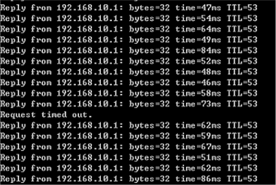
3.4 AC-Cluster
3.4.1 Understanding AC Cluster
Overview
Cluster means a group of coordinated service entities that provide more expandable and usable services platform than a single service entity. In a WLAN project, cluster means a group of coordinated ACs. Compared with the single-AC model, a group of coordinated ACs (cluster) provides higher usability (redundancy fault recovery) and load balancing.
AC Redundancy
In order to provide services for wireless users, AP must maintain connection with a specific AC. If this AC fails suddenly, AP will be unable to connect to AC and the service will fail. To enhance serviceability, the feature of AC redundancy is introduced.
AC redundancy assigns multiple ACs to the AP. When one AC fails, the AP can use the backup AC. AC redundancy well improves the reliability of AC cluster and avoid the circumstance that the downlink AP cannot provide services due to the failure of certain AC.
AC to Support the Failover Priority of AP
Generally, when the connection between AP and AC fails, the AP will look for the backup AC. By default, AP is connected to AC according to the sequence of association requests arrived. Failover Priority can help specify the priority level for AP, so that AC can accept the access request of AP according to the priority level of AP, ensuring that high-priority APs can be given the priority to connect to AC.
When the number of APs connected to AC has reached the threshold, if a new AP requests to associate with this AC and its priority level is higher than some connected APs, then AC will randomly kick out one AP among those associated APs with the lowest priority level. In this way, the new AP can then associate with this AC.
Difference to AC Hot-backup
Advantage:Both AC-1 and AC-2 forwards traffic in load balance way.
Disadvantage:It costs longer time than Hot-backup if AC-1 is down then switch the traffic to AC-2
3.4.2 Configuring AC Cluster
I. Network Topology
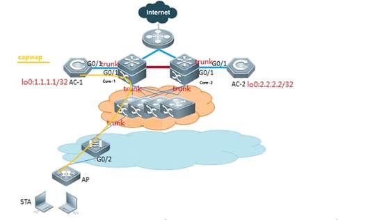
AC-1 is primary and AC-2 is secondary. AP establishes CAPWAP with AC-1. When AC-1 fails, the AP can use the backup AC-2.
II. Configuration Steps
3. Wlan basic configuration
Please view Basic Feature--Fit AP configuration section
3. Configuring AC Cluster(wlan-config ap-group and ap-name need to be the same)
AC-1:
AC-1(config)#interface loopback 0
AC-1(config-if-Loopback 1)#ip address 1.1.1.1 255.255.255.0
AC-1(config-if-Loopback 1)#exit
AC-1(config)#ac-controller
AC-1(config-ac)#ac-name AC-1
AC-1(config-ac)#exit
AC-1(config)#ap-config 0001.0001.0001 --->assume 0001.0001.0001 is AP MAC address, and it's the first time to configure AP
You are going to config AP(0001.0001.0001), which is online now.
AC-1(config)# ap-name AP
AC-1(config-ap)#ap-group ruijie
AC-1(config-ap)#primary-base AC-1 1.1.1.1
AC-1(config-ap)#secondary-base AC-2 2.2.2.2
AC-2:
AC-2(config)#interface loopback 0
AC-2(config-if-Loopback 1)#ip address 2.2.2.2 255.255.255.0
AC-2(config-if-Loopback 1)#exit
AC-2(config)#ac-controller
AC-2(config-ac)#ac-name AC-2
AC-2(config-ac)#exit
AC-2(config)#ap-config 0001.0001.0001
AC-2(config)# ap-name AP
AC-2(config-ap)#ap-group ruijie
AC-2(config-ap)#primary-base AC-1 1.1.1.1
AC-2(config-ap)#secondary-base AC-2 2.2.2.2
III. Verification
Connect wireless client to Wlan, simulate AC-1 interruption by reloading or power off, wireless client should be able to get wlan services in seconds.
3.5 Time Schedule
3.5.1 Turn off LED in Fixed Time
I. Requirements
Client wants to turn off AP LED in fixed time everyday automatically
II. Network Topology

III. Configuration Steps
Configuring turn off AP LED in fixed time
Fit AP
Configuring on AC
AC>enable
AC#configure terminal
AC(config)#schedule session 1
AC(config)#schedule session 1 time-range 1 period Wed time 13:30 to 20:20 ----->time range from 13:30 to 20:20 on Wednesday
AC(config)#clock timezone UTC +8 ---> set time zone, +8 hours offset
AC#clock set 11:33:00 8 6 2014 ---->set current time 11:33:00 6th Aug 2014
AC#show clock
AC#configure terminal
AC(config)#ap-config all
AC(config-ap)#quiet-mode session 1
AC(config-ap)#end
Recommend configure sntp, or the clock will return to the factory after reboot AP
AC(config)#sntp enable ----->enable sntp service
AC(config)#sntp server 192.168.2.1 ----->configure sntp server
AC#write
Fat AP
Configuring on Fat AP
FatAP>enable
FatAP#configure terminal
FatAP(config)#schedule session 1
FatAP(config)#schedule session 1 time-range 1 period Wed time 13:30 to 20:20
FatAP(config)#clock timezone UTC +8 ---> set time zone, +8 hours offset
FatAP#clock set 11:33:00 8 6 2014
FatAP#show clock
FatAP#configure terminal
FatAP(config)#quiet-mode session 1
FatAP(config-ap)#end
Recommend configure sntp, or the clock will return to the factory after reboot AP
FatAP(config)#sntp enable ----->enable sntp service
FatAP(config)#sntp server 192.168.2.1 ----->configure sntp server
FatAP#write
IV. Verification
3. ALL the LED, sys, wlan & wan LED on AP, are turned off
3. System prompts logs when quiet-mode takes effect:
[Wed, 13:55] Disable by schedule.
3.5.2 Turn off Radio in Fixed Time
I. Requirements
Client wants to turn off Radio in fixed time everyday automatically
II. Network Topology
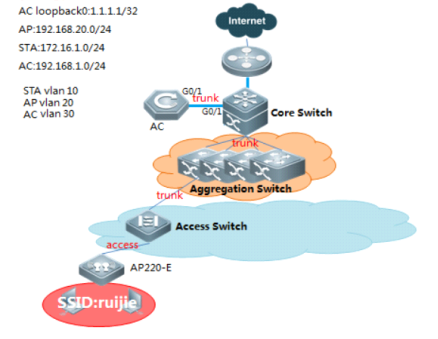
III. Configuration Steps
Configuring turn off Radio in fixed time
Fit AP
Configuring on AC
AC>enable
AC#configure terminal
AC(config)#schedule session 1
AC(config)#schedule session 1 time-range 1 period Wed time 13:30 to 20:20 ----->time range from 13:30 to 20:20 on Wednesday
AC(config)#clock timezone UTC +8 ---> set time zone, +8 hours offset
AC#clock set 11:33:00 8 6 2014 ---->set current time 11:33:00 6th Aug 2014
AC#show clock
AC#write
Below settings depends:
3. Turn off a certain WLAN
AC(config)#wlan-config 1
AC(config-wlan)# schedule session 1
3. Turn off a single Radio on a certain AP
AC(config)#ap-config 001a.a9120.ac09
AC(config-ap)#schedule session 1 radio 1
3. Turn off a single Radio on a group of APs
AC(config)#ap-group ruijie
AC(config-ap-group)#schedule session 1 radio 1
3. Recommend configure sntp, or the clock will return to the factory after reboot AP
AC(config)#sntp enable ----->enable sntp service
AC(config)#sntp server 192.168.2.1 ----->configure sntp server
AC#write
Fat AP
Configuring on Fat AP
FatAP>enable
FatAP#configure terminal
FatAP(config)#schedule session 1
FatAP(config)#schedule session 1 time-range 1 period Wed time 13:30 to 20:20
FatAP(config)#clock timezone UTC +8 ---> set time zone, +8 hours offset
FatAP#clock set 11:33:00 8 6 2014 --->set current time 11:33:00 6th Aug 2014
FatAP#show clock
FatAP#write
Below settings depends:
3. Turn off a certain WLAN
FatAP(config)#schedule session 1 wlan 1
3. Turn off a single Radio
FatAP(config)#ap-group ruijie
FatAP(config-ap-group)#schedule session 1 radio 1
3. Recommend configure sntp, or the clock will return to the factory after reboot AP
FatAP(config)#sntp enable ----->enable sntp service
FatAP(config)#sntp server 192.168.2.1 ----->configure sntp server
FatAP#write
IV. Verification
3. No wireless signal from 13:30 to 20:20 on Wednesday
3. Display ssid status, execute command on Fat or Fit AP "show dot11 mbssid". No output in the time range from 13:30 to 20:20 on Wednesday
Ruijie#show dot11 mbssid
3. System prompts below logs:
Ruijie(config)#00:00:11:01: %7: [Wed, 13:30] Disable wlan 1 by schedule.
Ruijie(config)#00:00:13:01: %7: [Wed, 20:20] Enable wlan 1 by schedule.
3.6 Wireless Multicast
I. Requirements
Have basic knowledge of IP multicast, IGMP Snooping and PIM (Protocol Independent Multicast).
II. Network Topology
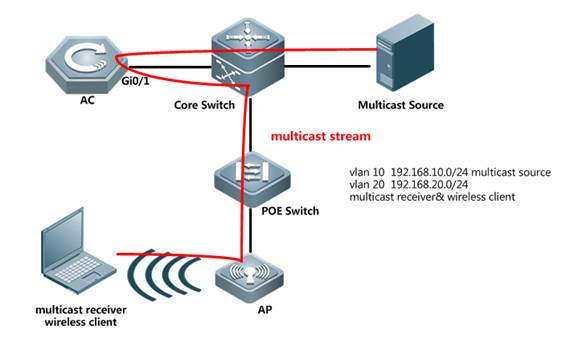
III. Configuration Steps
Configuring Wireless Multicast
AC
AC(config)#ip multicast wlan --->enable ip multicast globally
AC(config)#ip igmp snooping --->enable ip igmp snooping globally (require IP PIM enabled on Core Switch)
AC(config)#ap-config ap220-e --->enable ip igmp snooping on a specific AP
AC(config-ap)#igmp snooping
AC(config)#data-plane wireless-broadcast enable
Core Switch
CoreSwitch(config)#ip multicast-routing --->enable ip multicast
CoreSwitch(config)#interface vlan 10
CoreSwitch(config-VLAN 10)#ip pim dense-mode --->enable PIM
CoreSwitch(config)#interface vlan 50
CoreSwitch(config-VLAN 50)#ip pim dense-mode --->enable PIM
Notes: If the multicast doesn't in the same subnet or use spare mode, it needs to configure multicast RP role.
IV. Verification
Prepare multicase source and receiver, pump in multicast traffic and display IGMP Snooping status on AC, execute command "show ip igmp snooping mroute" and "show ip igmp snooping group"
Tips: you may simulate multicast traffic with tools "Wsend" and "Wlisten"
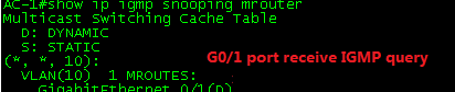
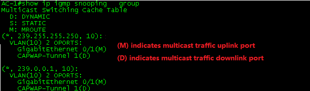
Also, display IGMP Snooping state on AP, execute command "show ip igmp snooping mroute" and "show ip igmp snooping gda-table"
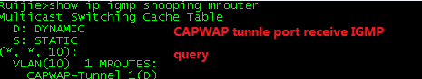
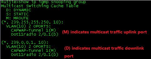
3.6.1 FAQ
3.6.1.1 How to adjust the wireless multicast packet sending rate
In fat mode:
Ruijie(config)#interface dot11radio 1/0
Ruijie(config-if-Dot11radio 1/0)#mcast_rate 54 ----->Adjusts the multicast rate to 54Mbps.
In fit mode:
Ruijie(config)#wlan-conf 1 wireless
Ruijie(config-wlan)#mcast_rate 54 ----->Adjusts the multicast rate to 54 Mbps.
3.6.1.2 How to configure the multicast-to-unicast function
The multicast-to-unicast function is used to make multicast video smoother.
Configuration reference:
(1) Enable the multicast routing protocol in a Layer-3 device in the same broadcast domain.
(2)
In fit (ap-config) mode, run the following command:
Ruijie(config)# ip igmp snooping ----->Enables igmp snooping for all VLANS. To enable this function for certain VLANs, run the ip igmp snooping vlan 1 command.
Ruijie(config)#ap-config xxx
Ruijie(config-ap)# igmp snooping mcast-to-unicast enable
Ruijie(config-ap)# igmp snooping mcast-to-unicast group-range ip-addr ip-addr ----->(Optional) Defines the multicast-to-unicast scope.
In fat mode, run the following command:
Ruijie(config)#ip igmp snooping ----->Enables igmp snooping for all VLANS. To enable this function for certain VLANs, run the ip igmp snooping vlan 1 command.
Ruijie(config)#ip igmp snooping mcast-to-unicast enable
3.6.1.3 Does AC support Layer-3 multicast?
No. But AC can transparently transmit Layer-2 multicast packets.
3.6.1.4 How to check whether CAPWAP multicast is enabled on AC or AP
Ruijie# show ip multicast wlan
Global multicast state: enable // Enables global multicast mode.
Multicast mode:multicast 239.0.0.1 // Enables CAPWAP multicast mode.
3.7 Local Forwarding
I. Requirements
Finishi reading
Have knowledge of the difference between Centralized and Local forwarding
Attention:In Roaming scenario, all APs IP address should be in a same IP subnets and brocast domain
II. Network Topology
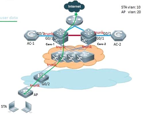
III. Configuration Steps
Configuring Local Forwarding
POE Switch
POESwtich(config)#interface gigabitEthernet 0/2
POESwtich(config-GigabitEthernet 0/2)#switchport mode trunk
POESwtich(config-GigabitEthernet 0/2)#switchport trunk native vlan 20 --->20 is AP management Vlan
POESwtich(config-GigabitEthernet 0/2)#switchport trunk allowed vlan remove 1-9,11-19,21-4094 --->Prune all vlans except for AP management Vlan and user data Vlan
AC
AC(config)#wlan-config 1 ruijie
AC(config-wlan)#tunnel local ----->enable local forwarding in WLAN 1
AC(config)#ap-group ruijie
AC(config-ap-group)#no interface-mapping 1 10 ----->all wireless user under this ap-group will be forced offline
AC(config-ap-group)#interface-mapping 1 10 --->Reassociate WLAN ID and VLAN ID to make configuration effect
IV. Verification
3. On AP, execute command "show run interface dot11radio 1/0", the mac-mode should be local

3. POESwtich learns the MAC address of wireless users on the downlink port that connects to AP
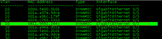
3.8 Wireless Authentication
3.8.1 3.1X Authentication
3.8.1.1 Understanding MAB on Wireless Device
In an IEEE 802 LAN, users can access t he network device without authorization and authorization as long as they are connected to the network device. Ther efore, an unauthorized user can access the network unobstructed by connecting the LAN. As the wide application of LAN technology, particularly the appearance of the operating network, it is necessary to address the safety authentication needs of the network. It has become the focus of concerns in the industry that how to provide user with the authentic ation on the legality of netwo rk or device access on the basis of simple and cheap LAN technologies. The IEEE 802.1x protocol is developed under such a context.
As a Port-Based Network Acce ss Control standard, the IEEE802.1x provides LAN access point-to-point security access. Specially designed by the IEEE Standardization Commission to tackle the safety defects of Ethernet, this standard can provide a means to authenticate the dev ices and users connected to the LAN by utilizing the advantages of IEEE 802 LAN.
The IEEE 802.1x defines a mode based on Client-Server to restrict unauthorized users from accessing the network. Before a client can access the network, it must first pass the authentication of the authentication server. Before the client passes the authentication, only the EAPOL (Extensible Authentication Protocol over LAN) packets can be transmitted over the network. After successful authentication, normal data streams can be transmitted over the network.
In the IEEE802.1x standard, there are three roles: supplicant, authenticator, and authentication server. In practice, they are the Client, network acce ss server (NAS) and Radius-Server.
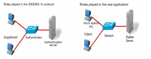
Supplicant:
The supplicant is a role played by the end user, usually a PC. It requests for the access to network services and acknowledges the request packets from the authenticator. T he supplicant must run the IEEE 802.1x client. Currently, the most popular one is the IEEE802.1x client carried by Windows XP. In addition, we have also launched the STAR Supplicant software compliant of this standard.
Authenticator:
The authenticator is usually an access device like the switch, AP or AC. The responsibility of the device is to control the connection status between client and the network according to the current authentication status of that client. Between the client and server, this device plays the role of a mediator, which requests the client for username, verifies the authentication information from the server, and forwards it to the client. Therefore, the swit ch acts as both the IEEE802.1x
Authenticator and the RADIUS Client, so it is referred to as the network ac cess server (NAS). It encapsulates the acknowledgement received from the client into the RADIUS format packets and forwards them to the RADIUS Server, while resolving the information received from the RADIUS Server and forwards the information to the client. The device acting as the authenticator has two types of ports: controlled Po rt and uncontrolled Port. The users connected to a controlled port can only access network resources after passing the authentication, while those connected to a uncontrolled port can directly access network resources without authentication. We can control users by simply connecting them to an controlled port. On the other hand, the uncontrolled port is used to connect the authentication server, for ensuring normal communication between the server and switch.
Authentication server:
The authentication server is usually an RADIUS server, which works with the authenticator to provide users with authentication services. The authentication server saves the user name and password and related authorization information. One server can provide authentication services for multiple authenticators, thus allowing centralized management of users. The authentication server also manages the accounting data from the authenticator. Our 802.1x device is fully compatible with the standard Radius Server, for example, the Radius Server carried on Microsoft WindowsServer and the Free Radius Server on Linux. In additional, we have already introduced the Radius server software SAM (Security Accounting Management Platform) complying with standards.
The supplicant and the authenticator exchange information by EAPOL protocol, while the authenticator and authentication server exchange information by RADIUS protocol, completing the authentication process with such a conversion. The EAPOL protocol is encapsulated on the MAC layer, with the type number of 0x888E. In addition, the standard has required for an MAC address (01-80-C2-00-00-03) for the prot ocol for packet exchange during the initial authentication process.
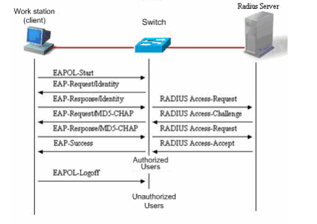
This is a typical authentication process initiated by users (in some special cases, the switch can actively initiate authentication request, whose process is the same as that shown in the diagram, except that it does not contain the step where the user actively initiates the request).
3.8.1.2 Configuring 802.1X Authentication
I. Network Topology
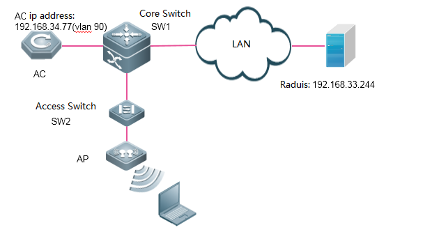
II. Configuration Steps
1. Enable 802.1x AAA authentication
AC-1(config)#aaa new-model ---->enable AAA authentication
AC-1(config)#aaa authentication dot1x default group radius ---->define the default group of dot1x authentication
AC-1(config)#aaa accounting network default start-stop group radius ---->define the default group of aaa accounting
2. Configure Radius server's IP addrsess and KEY
AC-1(config)#radius-server host 192.168.33.244 key ruijie ----> configure ip address and key of radiius server
AC-1(config)#ip radius source-interface bvi 90 ----> AC communicate with radius using the IP address of vlan 90
3. Configure parameters of 802.1x authentication
AC-1(config)#dot1x authentication default ----> use default list for dot1x authentication
AC-1(config)#dot1x accounting default ----> use default list for dot1x accounting
AC-1(config)#dot1x eapol-tag ----> make AC able to process authentication packets with VLAN tag
4. Enable 802.1X authentication
AC-1(config)#wlansec 1 ----> enable authentication on wlan 1
AC-1(config-wlansec)# security rsn enable
AC-1(config-wlansec)# security rsn ciphers aes enable
AC-1(config-wlansec)# security rsn akm 802.1x enable
5. Configure SNMP
AC-1(config)#snmp-server host 192.168.33.244 traps version 2c ruijie
AC-1(config)#snmp-server enable traps
AC-1(config)#snmp-server community ruijie rw
3. Configuring Portal Server and Radius Server
SMP:
3. Login to SMP server ---> "Authentication & Authority" ---> "Device" ---> "NAS Configuration Templates"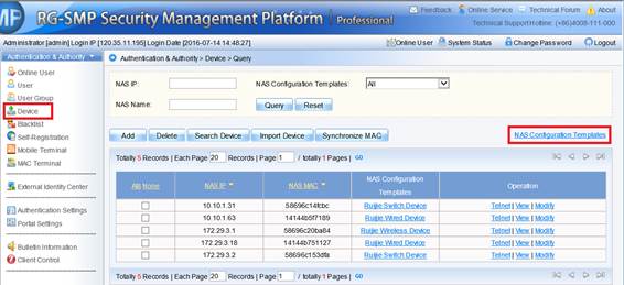
3. Choose "Ruijie Wireless Device", and click "Modify"

3. Configure "Identify Authentication Key" and "SNMP v2c Community"

3. Add new device, fill in the IP address of the AC, and select "Ruijie Wireless Device" as configuration Templates
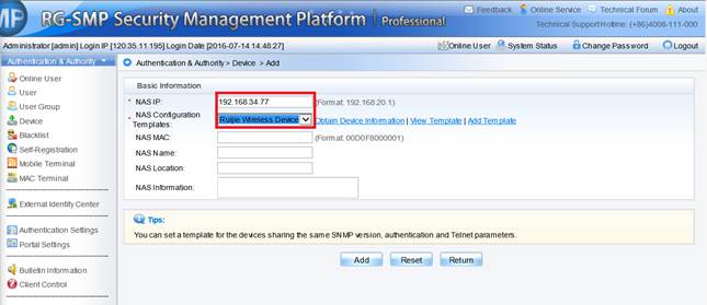
5. Add a new USER 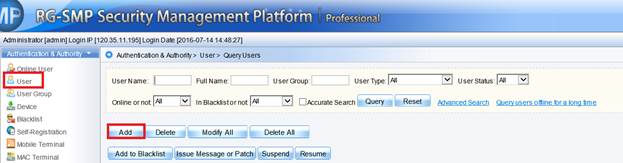
SAM
1) Login to SAM+ server --->"System" --->"Device Management"
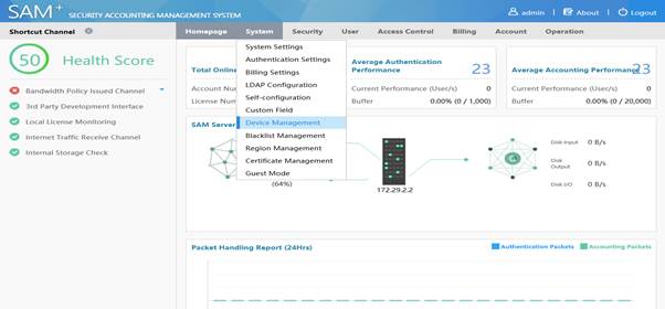
2) Select "Add"

3) Add device, fill in the related parematers "Device IP Address" "IP Type" "Device Type" "Model" "Device Key" "Community" and click "Save"
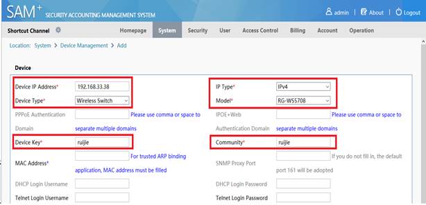
IV. Verification
3. Authenticate with built-in client of Windows. (See attached)
2. "Show dot1x summary" command shows online users
AC#show dot1x summary
ID MAC Address Username Interface VLAN Authen-State Backend-State User-Type Online-Duration
---------- -------------- ---------------- --------- ---- -------------- ------------- --------- ----------------
3 9c4e.36cc.f6dc lzm Ca1 10 Authenticated Idle static 0days 0h 0m27s
3. "show wclient security" command shows users' authentication type
AC#show wclient security 9c4e.36cc.f6dc
Security policy finished :TRUE
Security policy type :WPA-802.1X
WPA version :WPA2 (RSN)
Security cipher mode :CCMP
Security EAP type :PEAP
Security NAC status :CLOSE
3. Users are able to access the Internet
3.8.2 MAC Authentication Bypass (MAB)
3.8.2.1 Configuring MAB on Wireless Device
I. Network Topology
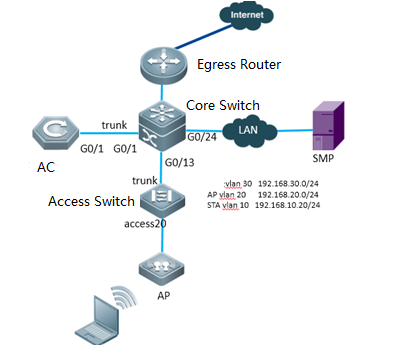
II. Configuration Steps
3. Enable MAB AAA authentication
Ruijie(config)#aaa new-mode ---->enable AAA authentication
Ruijie(config)#aaa group server radius MAB ---->define MAB raduis server list
Ruijie(config-gs-radius)# server 192.168.34.183
Ruijie(config)#aaa accounting network dot1x-mab start-stop group MAB ---->define the default group of accounting
Ruijie(config)#aaa authentication dot1x dot1x-mab group MAB ---->define the default group of authentication
2. Configure Radius server
Ruijie(config)#radius-server host 192.168.34.183 key ruijie ----> configure ip address and key of radiius server
3. Enable MAB on WLAN
Ruijie(config)#wlansec 1 ----> enable authentication on wlan 1
Ruijie(config-wlansec)# dot1x-mab
Ruijie(config-wlansec)# dot1x accounting dot1x-mab
Ruijie(config-wlansec)# dot1x authentication dot1x-mab
4. Configure SNMP server
Ruijie(config)#snmp-server enable traps
Ruijie(config)#snmp-server community ruijie rw
3.8.2.2 Configuring SMP Server
1) Login to SMP server ---> "Authentication & Authority" ---> "Device" ---> "NAS Configuration Templates"
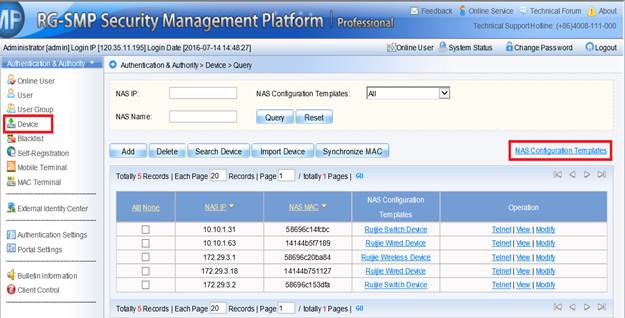
2) Choose "Ruijie Wireless Device", and click "Modify"
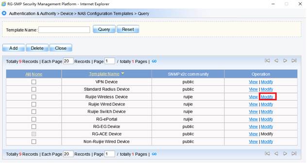
3) Configure "Identify Authentication Key" and "SNMP v2c Community"
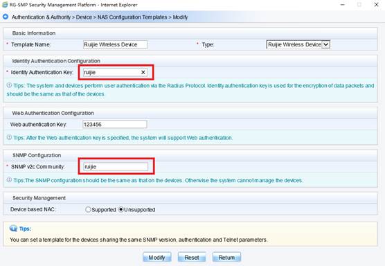
4) Add new device, fill in the IP address of the AC, and select "Ruijie Wireless Device" as configuration Templates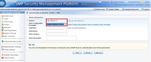
5) Add the MAC address of user's device
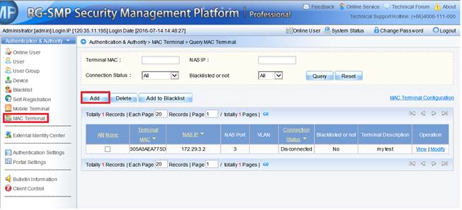
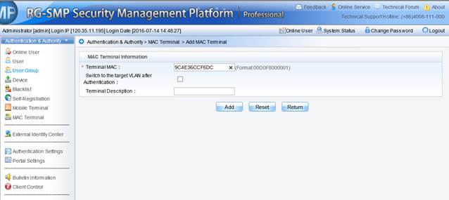
3.8.2.3 Configuring SAM+ Server
1) Login to SAM+ server --->"System" --->"Device Management"
2) Select "Add"
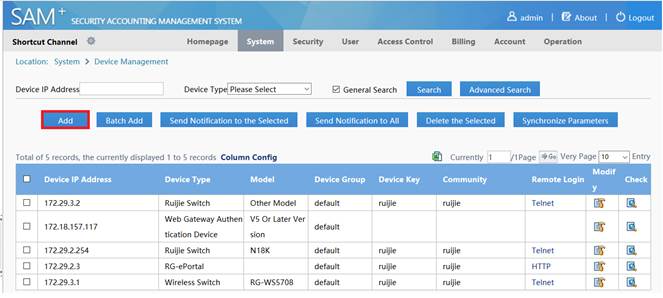
3) Add device, fill in the related parematers "Device IP Address" "IP Type" "Device Type" "Model" "Device Key" "Community" and click "Save"

4) Create a new account and set the device's mac address a username&password
PS: For some versions of SAM+, you may also need to unselect "Prohibit the use of crack Ruijie client" and "Prohibit the Use of Non Ruijie Client" in Access Control.
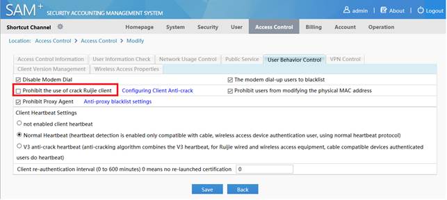
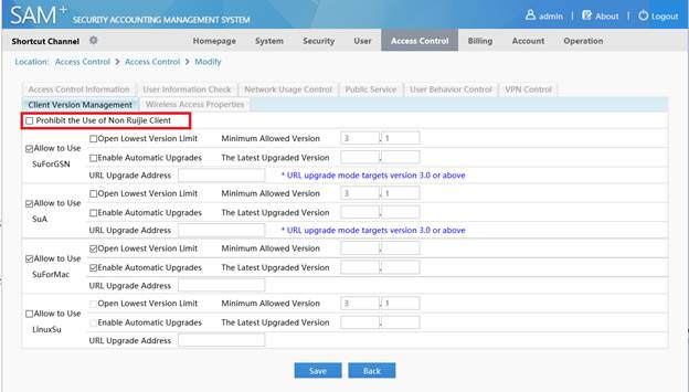
3.8.2.4 Verification
3. Connect SSID with two different STA: one is registered on AAA server, the other one is not. The registered STA is able to access the Internet, while the other one is not.
2. Check the online users on AAA server.
3. Show wireless users status on AC using command "show ac-config client"
AC#show ac-config client
========= show sta status =========
AP : ap name/radio id
Status: Speed/Power Save/Work Mode, E = enable power save, D = disable power save
Total Sta Num: 1
STA MAC IPV4 Address AP Wlan Vlan Status Asso Auth Net Auth Up time
-------------- --------------- ---------------------------------------- ---- ---- -------------- --------- --------- -------------
9c4e.36cc.f6dc 192.168.51.84 1414.4b65.3cf0/1 1 10 144.4M/D/bn MAB 0:00:01:47
3.8.3 Rruba clearpass Authentication
3.8.3.1 Configuring clearpass on Wireless Device
I. Network Topology
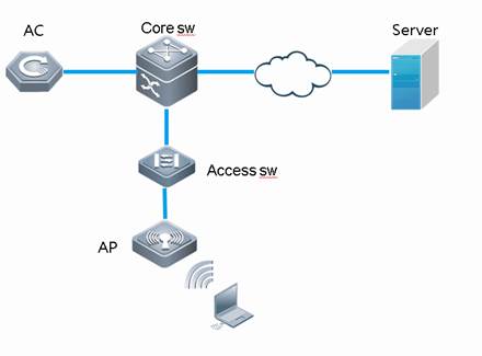
II. Configuration Steps
3. Enable http server
Ruijie(config)# web-auth auth-server ip 1.1.1.1 ---->Configure local http server, default ip is 1.1.1.1
Ruijie(config)# web-auth auth-server http ---->Open the monitor port, default is 8082
Ruijie(config)# web-auth auth-server submit-url http://1.1.1.1:8082/login ---->The authentication URL on AC, only support http, the ip and port should be match
2. Configure the template
Ruijie(config)#web-auth template cpweb ---->enable clearpass template
Ruijie(config.tmplt.cpweb)#ip x.x.x.x ---->clearpass server ip
Ruijie(config.tmplt.cpweb)#url http://x.x.x.x/guest/web_login.php ---->Redirect URL, support http and https
3. Enable AAA authentication
Ruijie(config)#aaa new-mode ---->enable AAA authentication
Ruijie(config)# aaa authentication cpweb default group radius ---->define the
Ruijie(config)# aaa accounting network default start-stop group radius ---->define the default group of accounting
Ruijie(config)# radius-server host x.x.x.x key ruijie ---->define the default group of authentication
4. Enable cpweb on WLAN
Ruijie(config)#wlansec 1 ----> enable authentication on wlan 1
Ruijie(config-wlansec)# web-auth portal cpweb
Ruijie(config-wlansec)# webauth
5. Enable https redirect
Ruijie(config)# http redirect port 443
6. Show auth status
Ruijie(config)# show web auth-server
3.8.4 Wifidog Authentication
3.8.4.1 Configuring wifidog on Wireless Device
I. Network Topology
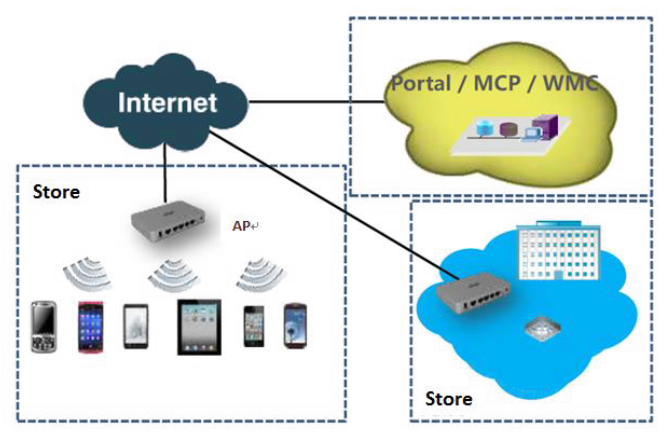
AP: Ruijie Access Points, This document provides the interface can also be applied to include EG gateway, AC and Fat AP series.
Portal: Authenticationand Portalserver, such as MCP, WMC or third part portal.
II. Flow process
1. Web Authentication Flow Process
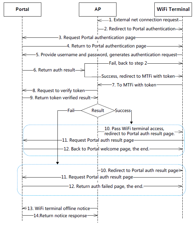
2. User MAB (MAC Authentication ByPass) Online Flow
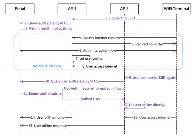
3. Configuration
III. Configuration Steps
3. Enable http server
Ruijie(config)# web-auth auth-server ip 1.1.1.1 ---->Configure local http server, default ip is 1.1.1.1
Ruijie(config)# web-auth auth-server http ---->Open the monitor port, default is 8082
Ruijie(config)# web-auth auth-server submit-url http://1.1.1.1:8082/login ---->The authentication URL on AC, only support http, the ip and port should be match
2. Configure the template
Ruijie(config)#web-auth template cpweb ---->enable clearpass template
Ruijie(config.tmplt.cpweb)#ip x.x.x.x ---->clearpass server ip
Ruijie(config.tmplt.cpweb)#url http://x.x.x.x/guest/web_login.php ---->Redirect URL, support http and https
3. Enable AAA authentication
Ruijie(config)#aaa new-mode ---->enable AAA authentication
Ruijie(config)# aaa authentication cpweb default group radius ---->define the
Ruijie(config)# aaa accounting network default start-stop group radius ---->define the default group of accounting
Ruijie(config)# radius-server host x.x.x.x key ruijie ---->define the default group of authentication
4. Enable cpweb on WLAN
Ruijie(config)#wlansec 1 ----> enable authentication on wlan 1
Ruijie(config-wlansec)# web-auth portal cpweb
Ruijie(config-wlansec)# webauth
5. Enable https redirect
Ruijie(config)# http redirect port 443
6. Show auth status
Ruijie(config)# show web auth-server
3.9 Web Authentication
3.9.1 Understanding Web Authentication
Overview
Web authentication is a authentication method for controlling users' network access. This authentication method does not require users to install special client authentication software, and the authentication is supported by general browsers.
When an unauthenticated user accesses the network using a browser, the network access device directs the browser to a specific site, namely the Web authentication server, which is called the Portal Server, and the user can access part of services without authencation, such as downloading security patches and reading announcements. If the user desires to access other network resources beyond the authentication server, he/she must pass authentication at the Portal server via the browser. Only authenticated users can get access to the Internet.
Besides the convenience in the authentication, since the portal server and the user browser have page interactions which can be used for personalizing service such as posting advertise ments, notices and business interlinks on the portal server page, therefore, it has a promising prospect.
HTTP Interception and HTTP Redirection are two important components in Web Authentication
HTTP Interception
HTTP interception means the access device blocks HTTP packets which are intended to be forwarded. Such HTTP packets are sent by users' browsers that are connected to access devices but not destined to these devices. For example, a user uses IE to access www.google.com, the access device is expected to forward its HTTP request packets to the gateway. However, if HTTP interception is enabled, these packets will not be forwarded.
After the HTTP interception, the access device directs the HTTP connection requests from the user to itself and thus establishes a session between the access device and the user. The access device uses the HTTP redirection function to push the redirection page to the user, and the user’s browser will show a window which may require authentication, or may display a link for downloading software.
With Web authentication function, it is possible to set which users' HTTP packets to the destination ports are to be blocked, and which are not to be blocked. Generally, HTTP requests from unauthenticated users are intercepted, and those from authenticated users are not intercepted. HTTP interception is the foundation of Web authentication. The Web authentication process is automatically trig gered once HTTP interception takes place.
HTTP Redirection
According to the HTTP protocol, generally, after a user's browser sends HTTP GET or HEAD request packets, the receiver responds with a 200 message if it is able to provide the required resources, or the receiver responds with a 302 message if it is unable to do so. A new site path is provided in the 302 message. After the user has received the response, it may re-send the HTTP GET or HEAD request packets to the new site for requesting resources, which is called redirection.
HTTP redirection is an important part of Web authentication and takes place after HTTP interception. It uses the special characteristic of the 302 message in the HTTP protocol. HTTP interception leads to the creation of a session between the access device and the user. After that, the user sends the HTTP GET or HEAD request packets (which should have been sent to another site) to the access device, which then responds with a 302 message and specifies the site path of the redirection page in the 302 message. In this way, the user re-sends the requests along to the new site path and gets the redirection page.
Attentions:
In Ruijie System, there're two kinds of WEB Authentications: Ruijie Web Authentication V2 and Built-in Web Authentication. Usually, we implement in below ways:
In Ruijie Web Authentication V2,
3. The portal is an additional single server, like Ruijie SMP (Secure Management Platform).
3. The user identities & password are stored in Radius Server, like Ruijie SMP (Secure Management Platform).
3. It is more powerful, flexible and complicated than Built-in Web Authentication.
In Built-in Web Authentication,
3. The portal is built in AC, no additional portal server is required
3. The user identitis&password are stored in AC local database, OR in Radius Server, like Ruijie SMP (Secure Management Platform).
3. The performance, user throughput and authentication methods are not as strong as Ruijie Web Authentication V2.
Ruijie Web Authentication V2
Components
Components in a complete Web authentication work flow: End user, access device, Portal Server, Radius Server
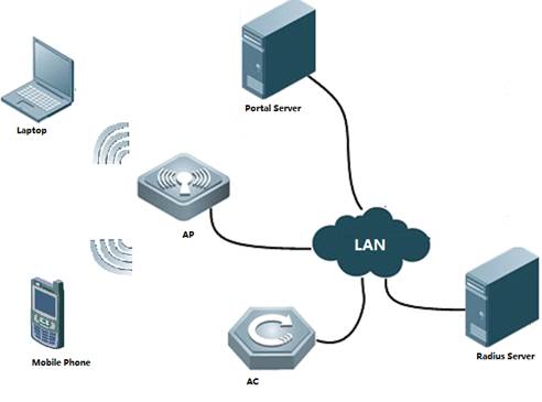
3.End user(STA):A computer, a mobile phone or a pad which runs HTTP protocol and with which users visit Internet.
3.Access device(AC&AP):Generally refers to an access layer device (for example, a wireless AP in a WLAN) in the network topology. It is generally directly connected to the user's terminal device, and web authentication must be enabled on the access device. The access device receives the authentication information of the user from the Portal server, and sends an authentication request to the RADIUS server. The access device determines whether the user can access the Internet based on the authentication results and replies the results to the Portal server.
3.Portal Server:For example, Ruijie SMP (Secure Management Platform), it provides authentication page and related operation for web authentication. When the Portal server receives HTTP-based authentication requests sent by the authentication client, it collects account information and sends it to the access device, and then replies the result to the user via the page according to the authentication results from the access device.
3.Radius Server:For example, Ruijie SMP (Secure Management Platform), it provides standard radius protocol-based remote authentication.
Authentication Work FLow
3. Before authentication, the access device blocks all HTTP requests sent by the unauthenticated user and redirects the requests to the Portal server. Then, an authentication window pops up in the user's browser.
3. During authentication, the user inputs the authentication information (username, password and verification code.) on the authentication page to interact with the Portal server.
3. The Portal server sends the authentication information of the user to the access device.
3. The access device initiates an authentication request to the RADIUS server and replies the result to the Portal server.
3. The Portal server responds to the user with a page to indicate the result (success or failure).
For details, see diagram below:
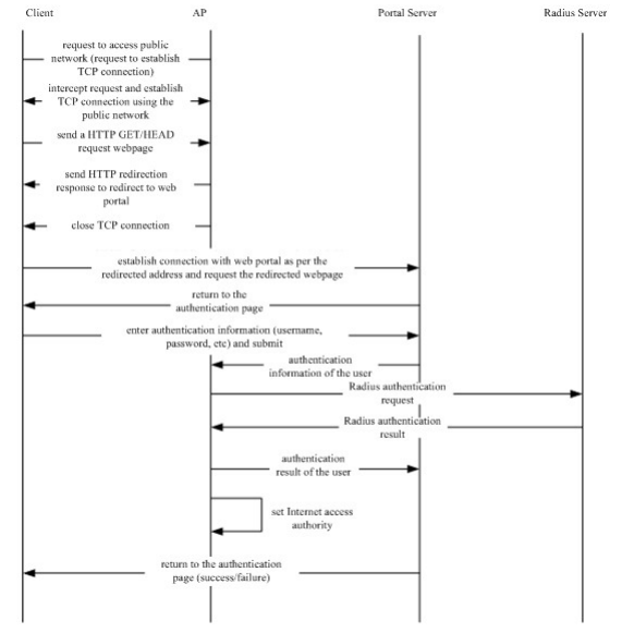
User Logout
There are two types of user logout:
One is the user logout detected by the access device because user's time is out, the traffic data is used up or the link is interrupted.
The other is that the user logout detected by the Portal Server because the user triggers the logout application through a logout page.
Scenario 1: The access device detects the user's logout and informs the Portal Server, and then the Portal Server deletes the user information (through portal protocol), and the Portal Server will then inform the user through a logout page.
Scenario 2: T he Portal Server detects the user's logout and informs the access device (through portal protocol) and informs the user with a logout page.
In the above two scenarios, the Portal Server will send a st op-accounting request to the Radius Server and notify the Radius Server that the user has logged out.
Built-in Web Portal
Components
Components in a complete Web authentication work flow: End user, access device, Portal Server, Radius Server
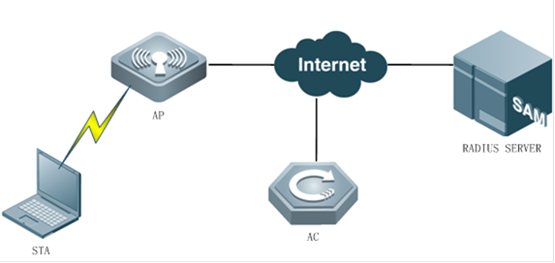
3.End user:A computer, a mobile phone or a pad which runs HTTP protocol and with which users visit Internet.
3.Access device(AC&AP):Generally refers to an access layer device (for example, a wireless AP in a WLAN) in the network topology. It is generally directly connected to the user’s terminal device, and web authentication must be enabled on the access device. The access device receives the authentication informat -ion of the user from the Portal server, and sends an authentication request to the RADIUS server. The access device determines whether the user can access resources of the Internet based on the authentic ation results and replies the results to the Portal server.
3.Radius Server:For example, Ruijie SMP (Secure Management Platform), it provides standard radius protocol-based authentication of remote users.
Authentication Work FLow
3. Before authentication, the access device will intercept all HTTP requests sent by unauthentic ated users and redirect such requests to the Portal authentication page, then an authentication page will pop up on user's browser.
3. During authentication, the user will type in the authentication information (username, password, validation code, etc) on the authentication page to interact with the built-in portal module of device.
3. The built-in portal module will then submit user's authentication information to the authentication module of access device.
3. The authentication module accepts user's authentication request, indirectly initiate an authentication request to the Radius Server and forward the authentication result to the Portal Server.
3. The built-in portal module will respond the user with a webpage indicating the aut hentication result (login page/success or failure information).
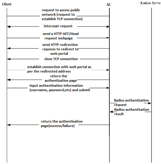
User Logout
The access device detects the user's logout through the information on the logout page of the built-in Portal Server, or the link is lost or no online hours or traffic is available.
The access device sends a stop-accounting request to the Radius Server and logs out the user.
The built-in Portal Server responds to the user with a successful logout page.
3.9.2 Built-in Web Portal & Local Authentication
I. Requirements
3. Finish Common Features --> FIT AP Basic configuration
II. Network Topology
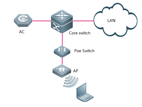
III. Configuration Steps
3. Configuring AAA
AC#config terminal
AC(config)#aaa new-model ---->enable AAA authentication
AC(config)#aaa accounting network default start-stop none ---->disable aaa accounting
AC(config)#aaa authentication iportal default local ----> authenticaticate with local accounts
3. Configuring local accounts
AC(config)#username admin web-auth password admin ------>configure local username and password
3. Bypass arp packets of wireless user gateway
AC(config)#http redirect direct-arp 192.168.51.1 ------>192.168.51.1 is wireless users' gateway
3. Enable https
AC(config)#http redirect port 443
3. Configuring Wlansec
AC(config)#web-auth template iportal ------>need to add this command
AC(config)#wlansec 1 ----> enable authentication on wlan 1
AC(config-wlansec)#web-auth portal iportal
AC(config-wlansec)#webauth
AC(config-wlansec)#end
3. Saving configuration
AC#write
IV. Verification
3. Connect to wireless ssid, authentication page pops up, input useranme / password, pass the authentication, and start visiting Internet.
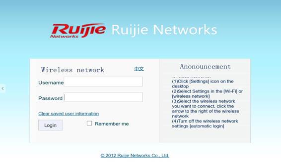
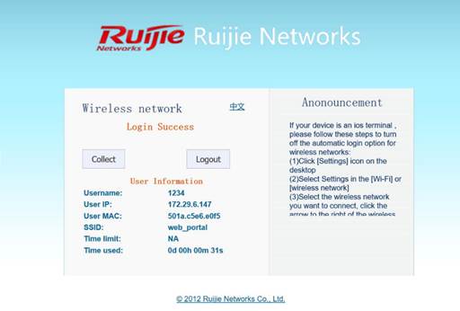
3. Execute command "show web-auth user all" on AC to display authenticated online users.
AC#show web-auth user all
Statistics:
Type Online Total Accumulation
-------------- ------- ------- ------------
v1 portal 0 0 1
v2 Portal 0 0 11
Intra Portal 1 1 2
-------------- ------- ------- ------------
Total 1 1 14
V1 Portal Authentication Users
Index Address Online Time Limit Time used Status
----- ---------------------------------------- ------ ------------ ------------ -------
----- ---------------------------------------- ------ ------------ ------------ -------
Intra Portal Authentication Users
Index Address Online Time Limit Time used Status
----- ---------------------------------------- ------ ------------ ------------ -------
1 192.168.51.29 On 0d 00:00:00 0d 00:00:00 Active
----- ---------------------------------------- ------ ------------ ------------ -------
V2 Portal Authentication Users
Index Address Online Time Limit Time used Status
----- ---------------------------------------- ------ ------------ ------------ -------
----- ---------------------------------------- ------ ------------ ------------ -------
3.9.3 Built-in Web Portal & Radius Authentication
I. Network Topology
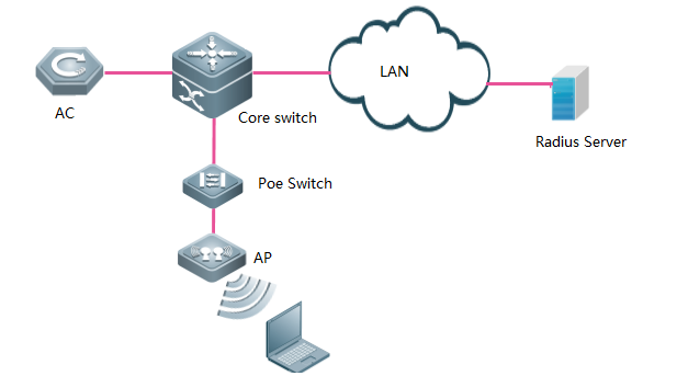
II. Configuration Steps
3. Confiruing AAA
AC#config terminal
AC(config)#aaa new-model ---->enable AAA authentication
AC(config)#aaa accounting network default start-stop group radius ---->define the default gourp of accounting
AC(config)#aaa authentication iportal default group radius ---->define the default gourp of web authentication
3. Configuring Radius Server Parameters
AC(config)#radius-server host 192.168.51.103 key ruijie ---->configure the IP address and key of radis server
AC(config)#ip radius source-interface vlan 1
AC(config)#radius-server attribute 31 mac format ietf
3. Bypass arp packets of wireless user gateway
AC(config)#http redirect direct-arp 192.168.51.1 ------>gateway of wireless users
3. Enable redirect port
AC(config)#http redirect port 8081
3. Configuring Wlansec
AC(config)#web-auth template iportal ------> need to add this command
AC(config.tmplt.iportal)#exit
AC(config)#wlansec 1 ----> enable authentication on wlan 1
AC(config-wlansec)#web-auth portal iportal
AC(config-wlansec)#webauth
AC(config-wlansec)#exit
3. Configuring SNMP
AC(config)#snmp-server community ruijie rw
3. Configuring username&password saving Configuration
AC(config)#username admin password admin ------>configure username and password for user login
AC(config)#end
AC#write
3. Configuring Radius Server
Suggest install standard Radius Server, like Ruijie SMP (Security Management Platform)
For detail, visit Ruijie official website at http://www.ruijienetworks.com, Categoery "Software"
You may also install other 3rd party Radius Server.
III. Verification
3. Connect to wireless ssid, authentication page pops up, input useranme / password, pass the authentication, start visiting Internet.

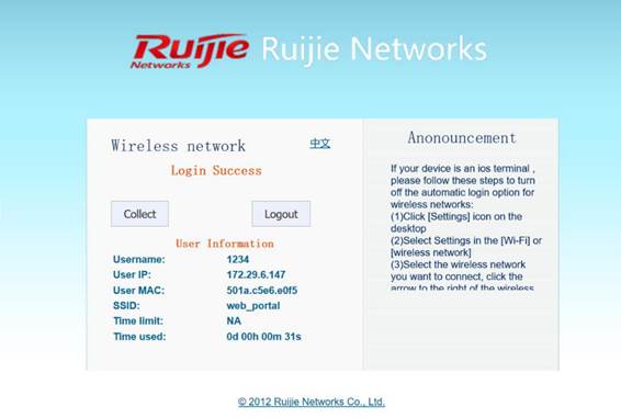
3. Execute command "show web-auth user all" on AC to display authenticated online users.
AC#show web-auth user all
Statistics:
Type Online Total Accumulation
-------------- ------- ------- ------------
v1 portal 0 0 1
v2 Portal 0 0 11
Intra Portal 1 1 1
-------------- ------- ------- ------------
Total 1 1 13
V1 Portal Authentication Users
Index Address Online Time Limit Time used Status
----- ---------------------------------------- ------ ------------ ------------ -------
----- ---------------------------------------- ------ ------------ ------------ -------
Intra Portal Authentication Users
Index Address Online Time Limit Time used Status
----- ---------------------------------------- ------ ------------ ------------ -------
1 192.168.51.29 On 240d 00:00:00 0d 00:00:00 Active
----- ---------------------------------------- ------ ------------ ------------ -------
V2 Portal Authentication Users
Index Address Online Time Limit Time used Status
----- ---------------------------------------- ------ ------------ ------------ -------
----- ---------------------------------------- ------ ------------ ------------ -------
3.9.4 Ruijie Web Authentication V2 & Radius Authentication
I. Network Topology
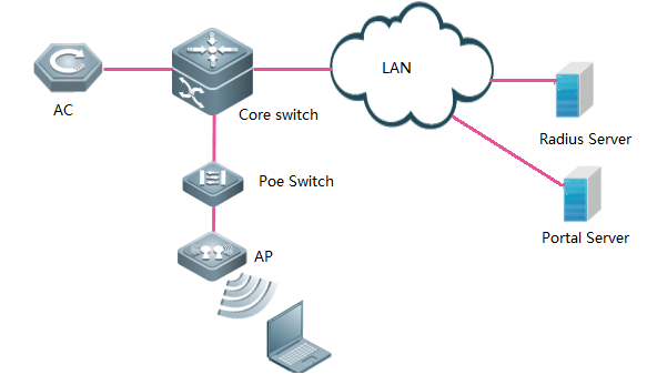
II. Configuration Steps
3. Configuring AAA
AC#config terminal
AC(config)#aaa new-model ------>enable AAA authentication
AC(config)#aaa accounting network default start-stop group radius ---->define the default gourp of accounting
AC(config)#aaa authentication web-auth default group radius ---->define the default gourp of web authentication
AC(config)#aaa accounting update ---->enable accounting
AC(config)#aaa accounting update periodic 15 ---->define update periodic
3. Configuring Radius Server Parameters
AC(config)#radius-server host 192.168.51.103 key ruijie ---->configure the IP address and key of radis server
AC(config)#ip radius source-interface bvi 1
AC(config)#radius-server attribute 31 mac format ietf
AC(config)#web-auth portal key 123456 ------>the key should match in Portal Server
3. Configuring portal-server. Wireless user will be redirected to this authentication page
【3.X configuration command】
AC(config)#portal-server eportalv2 ip 192.168.51.38 url http://192.168.51.38/eportal/index.jsp ------>this URL is just a sample, it depends on portal-server you are configuring.
【3.X configuration command】
AC(config)#web-auth template eportalv2
AC(config.tmplt.eportalv2)#ip 192.168.51.38
AC(config.tmplt.eportalv2)#url http://192.168.51.38/eportal/index.jsp
AC(config.tmplt.eportalv2)#exit
3. Bypass arp packets of wireless user gateway
AC(config)#http redirect direct-arp 192.168.51.1 ------>gateway of wireless users
3. Configuring Wlansec
AC(config)#wlansec 1 ----> enable authentication on wlan 1
AC(config-wlansec)#webauth
AC(config-wlansec)#web-auth portal eportalv2
AC(config-wlansec)#exit
3. Configuring SNMP
AC(config)#snmp-server host 192.168.51.103 traps version 2c ruijie ------>192.168.51.103 is Radius Server IP address. Here takes Ruijie SAM+ for example.
AC(config)#snmp-server host 192.168.51.38 traps version 2c ruijie ------>192.168.51.38 is Portal Server IP address. Here takes Ruijie e-portal for example.
AC(config)#snmp-server enable traps web-auth
AC(config)#snmp-server community ruijie rw
3. Configuring username&password and saving configuration
AC(config)#username admin password admin
AC(config)#end
AC#write
3. Configuring Portal Server and Radius Server
Here takes Ruijie SAM+as example. For detail, visit Ruijie official website at http://www.ruijienetworks.com, Categoery "Software"
You may also install other 3rd party Portal servers and Radius Server.
III. Verification
3. Connect to wireless ssid, authentication page pops up, input useranme / password, pass the authentication, start visiting Internet.


3. Execute command "show web-auth user all" on AC to display authenticated online users.
AC#show web-auth user all
Statistics:
Type Online Total Accumulation
-------------- ------- ------- ------------
v1 portal 0 0 1
v2 Portal 1 1 112
Intra Portal 0 0 0
-------------- ------- ------- ------------
Total 1 1 12
V1 Portal Authentication Users
Index Address Online Time Limit Time used Status
----- ---------------------------------------- ------ ------------ ------------ -------
----- ---------------------------------------- ------ ------------ ------------ -------
Intra Portal Authentication Users
Index Address Online Time Limit Time used Status
----- ---------------------------------------- ------ ------------ ------------ -------
----- ---------------------------------------- ------ ------------ ------------ -------
V2 Portal Authentication Users
Index Address Online Time Limit Time used Status
----- ---------------------------------------- ------ ------------ ------------ -------
1 192.168.51.29 On 240d 00:00:00 0d 00:00:00 Authenticated
----- ---------------------------------------- ------ ------------ ------------ -------
3.9.5 Ruijie Web Portal Customization
AC Built-in Portal Customization
Step 1, log on to wireless controller via CLI, execute command dir to display file/folder list
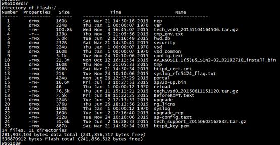
Step 2, enter folder portal by command cd portal, execute dir to display list
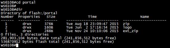
Step 3, enter folder zip, default.zip is the http package for iportal (built-in portal)
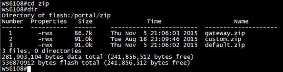
step 4, setup tftp server on your local laptop, transfer default.zip back. We will use it as http code template.
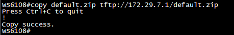
step 5, decompress this zip file, you will get a file list as shown below,
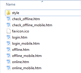
Description:
login.htm > PC login page
login_mobile.htm > mobile login page
offline.htm >PC offline page
offline_mobile.htm > mobile offline page
online.htm > PC online page
online_mobile.htm > mobile online page
Enter folder Style, you will get below file list.
If you are good at HTML coding, I believe you should know very well how to move on next.
If not, let’s do an example ---replace the logo on English PC login page
Step 6, prepare a gif format picture with dimensions 468 x 105, name it as en_logo.gif, and cover the original one.

![]()
<Original logo>

![]()
<New logo>
When finished, open login.htm to verify
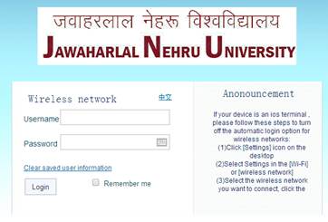
The logo on English login page has changed.
Step 7, for other *.htm customization, read above steps 5 and 6.
Step 8, package the customized files into ZIP format, and upload it to path/portal/zip on wireless controller
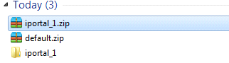
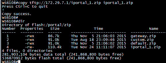
Step 9, apply customized http package to iportal setting.
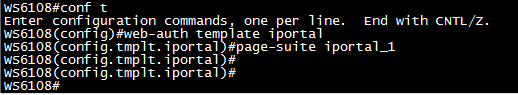
Note: your iportal web template may not be named as” iportal “
Verification
The logo has been replaced.
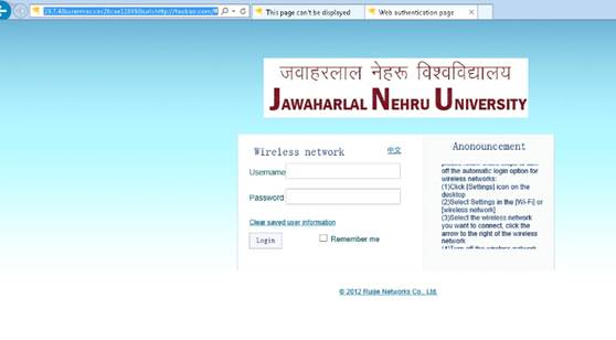
SMP Built-in Portal Customization
1) Login to SMP server ---> "System Maintenance" ---> "Custom Manager Page"
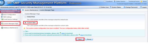
2) Select a specific picture and click "Upload" button
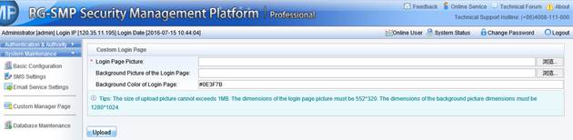
If you want to customize the welcome words on the login page. You could access the "common_user_auth_login" file in SMP server and modify the related characters.
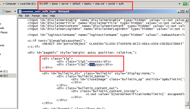

Warm prompt:
You could also customize the web portal page via eweb, for more details, please find the attachment for your reference.
3.9.6 FAQ
3.9.6.1 How to view the information of authenticated users in Web authentication mode?
WS#show web-auth user ?
all Process all users ------Displays all the authentication users.
escape Web-auth user escape ------Display escaped users who connect WeChat accounts to Wi-Fi through MCP.
ip User ip address ------Displays authentication information of an IP address.
mac User MAC ------Displays authentication information of an MAC address.
name User name ------Displays authentication information of a user.
3.9.6.2 How to force a web-auth user offline?
WS#clear web-auth user ?
all Process all users
ip User ip address
mac User MAC
name User name
Note: Before going online, the cleared terminal must be authenticated again.
3.9.6.3 How to display the HTTP redirection configuration
Ruijie#show http redirect
HTTP redirection settings:
server: 172.20.1.100 // Indicates the IP address of the Portal server.
port: 80
homepage: http://172.20.1.100:8888/eportal /index.jsp // Indicates the authentication homepage URL of the Portal server.
session-limit: 255
timeout: 3
Direct sites:
Address MASK ARP Binding
---------------- ---------------- -----------
3.18.10.1 255.255.255.255 Off // Indicates that the resources can be accessed without authentication.
Direct hosts:
Address Mask Port Binding ARP Binding
---------------------------------------- ---------------- ------------- -----------
192.168.20.1 255.255.255.255 Off // Indicates that users do not to be authenticated.
3.9.6.4 How to display Web authentication configurations
Ruijie#show web-auth portal
Portal Servers Settings:
------------------------------------------------------------
Ip: 172.18.159.48
Key: ruijie
ref: 2
------------------------------------------------------------
Ip: 172.18.159.46
Key: ruijie
ref: 1
portalv2 list show
------------------------------------------------------------
Ip: 172.18.159.48
port: 50100
ref: 2
URL format: default
Status: Enable
Ip: 172.18.159.46
port: 50100
ref: 1
URL format: default
Status: Enable
3.9.6.5 How to display the template and port parameters configured by the device on the AC?
WS#sh web-auth template
Name: zzs2
BindMode: ip-mac-mode
Type: v2
Port: 50100
Ip: 2.2.2.2
Url: http://2.2.2.2/eportal/index.jsp
The Portal server uses the local port 50100 to monitor and authenticate non-response packets send by the device and uses the target port 2000 to send all packets to the authentication device.
NAS uses the local port 2000 to monitor all packets send by the Portal server and uses the target port 50100 to send non-response packets to the Portal server.
3.9.6.6 How does the traffic Detection of Web Authentication work
Traffic detection is enabled in Web authentication mode by default. When a user having passing Web authentication has no traffic passing through the device within the specified no traffic period, the device deems that the user has gone offline and kicks the user out.
AP 11.x supports global no traffic detection and wlansec no traffic detection. The wlansec no traffic detection has a higher priority. When wlansec no traffic detection takes effect, global no traffic detection does not take effect.
In global no traffic detection mode, if the user has no traffic in eight hours, the user is kicked off by default. The command is as follows:
Ruijie(config)# offline-detect interval xx threshold yy
xx indicates the time, which is an integer ranging from 1 to 65535, and the unit is minute. The default value is 8 hours.
yy indicates the traffic size, which is an integer ranging from 0 to 4,294,967,294, and the unit is byte. The default value is 0.
In wlansec no traffic detection mode, if the user has no traffic in 15 minutes, the user is kicked off by default. The command is as follows:
The wlansec no traffic detection has a higher priority. Therefore, users having no traffic in 15 minutes are kicked out in 15 minutes by default.
WS(config)#wlansec 7 -------It is the actual authenticated wlansec serial number.
WS(config-wlansec)#web-auth offline-detect ?
flow Configure no flow threshold
interval Configure no flow interval
3.9.6.7 Does built-in Web authentication support pushing advertisement without authentication or pushing advertisement after authentication?
No.
3.9.6.8 Can an account be logged on by only a single user in local built-in Web authentication mode?
No. To control the number of simultaneous logons to the terminal, a separate authentication server should be configured and the server should support this function.
3.9.6.9 the traffic keepalive detection is based on the user MAC address or user name in Web authentication mode?
It is based on the user MAC address.
3.9.6.10 What are the protocol and port used by wireless second-generation Web authentication?
The protocol is UDP.
The packet target port of the Portal server is port 2000, which means that the port used by the AC to send packets is port 2000.
3.9.6.11 Is wireless user data encrypted at the air interface in wireless Web authentication?
If only Web authentication is enabled, the data is not encrypted at the air interface. You can configure WPA2 to encrypt the data.
3.9.6.12 Can the Portal server IP address be configured to a domain name on the AC?
Yes. The URL should be added to the URL whitelist. On AC 11.1(5)b8 or a later version, you are recommended to run the free-url url xx command to make the configuration in global mode.
For example, run the WS(config)#free-url url www.google.com command to add www.google.com in the whitelist.
3.9.6.13 Does the AC support https redirection and which redirection port need to be configured?
Currently, only ACs of 11.1(5)B8p3, 11.1(5)B9P5, office-wifi and later versions support https redirection. The redirection ports 433 and 8433 must be configured as follows:
Ruijie(config)#http redirect port 443
Ruijie(config)#http redirect port 8443
3.9.6.14 If the terminal uses a static IP address in Web authentication mode, can the IP address of the terminal be uploaded to the server?
The AC 11.1(5)b8p3 and later versions allow you to run the dot1x get-static-ip enable command to upload the static IP address of the wireless terminal to the server.
3.9.6.15 How to bypass specific devices in Web authentication mode?
In some applications, after connecting to a wireless network, users can access some network resources (for example, intranet websites) without authentication. You can run the http redirect direct-site x.x.x.x command (x.x.x.x is the IP address of free-authenticated resources) to add the IP address of these websites to the free-authenticated network resource list.
3.9.6.16 How to fix when “the authentication device does not exist” error occurs during Web authentication?
After confirming that the AC is added to the server and the authentication key configurations are consistent, check whether the AC can ping the server and modify the source IP address of the Portal server and RADIUS server according to actual situation. Add the VLAN of IP addresses of servers that can be pinged.
Ruijie(config)#ip portal source-interface vlan 1
Ruijie(config)#ip radius source-interface vlan 1
3.9.6.17 Timeout connection error is reported when the built-in portal web authentication fails.
(1) If the communication between the AC and the RADIUS server fails, check whether the routes are different because multiple IP addresses are set for the RADIUS server.
(2) No AC is added to the RADIUS server. Check whether the SAM is added with an AC.
(3) The RADIUS key configuration is inconsistent. Check whether the SAM is added to the AC for more than two times (the IP address of the uplink interface of the AC is added).
(4) The proxy is enabled for the Internet Explorer but the built-in Portal does not support the proxy. Disable the proxy of the Internet Explorer.
3.9.6.18 Error code analysis for User Offline in Second Generation Web Authentication Mode
01: The user actively goes offline.
02: The port is disconnected. On a wireless network, STAMG notifies STA to go offline. In this case, contact STAMG owner to locate the cause.
03: The service is unavailable mainly due to connection interruption.
04: Idle status times out. The user having no traffic is kicked out.
05: Session times out. The duration reaches.
06: The administrator resets the port or session to kick out users from the RADIUS server, kick out escaped users after restoring the Portal server, or run the clear command to delete users.
07: The administrator restarts NAS.
08: The port has an error and required to interrupt the session
09: NAS has an error and required interrupting the session.
10: NAS requires interrupting the session due to other reasons.
11: NAS is restarted accidentally.
12: NAS thinks there is no need to retain the port and interrupts the session.
13: NAS interrupts the session to allocate this port.
14: NAS interrupts the session to suspend the port.
15: NAS fails to provide the required service.
16: NAS interrupts the current session to call back the new session.
17: Information entered by the user is incorrect.
18: The host requires interrupting the session.
103: The IP or MAC address has changed or occupied.
115: The service is switched over.
122: The traffic is exhausted.
250: The low-traffic user is kicked out. It is a unique attribute of Ruijie AP and the cause is same to code 4.
500: Authentication times out. The RADIUS authentication packet is not responded within the time limit. This attribute is available for wireless wlog module and will be provided for SNC later.
501: Authentication is denied by the RADIUS server. This attribute is available for wireless wlog module and will be provided for SNC later.
502: The number of users on the device has reached the upper limit. This attribute is available for wireless wlog module and will be provided for SNC later.
3.9.6.19 Definition of errcode in the Portal Protocol
(1) When the Type value is set to 2, in ack_challenge:
ErrCode = 0: The AC informs the Portal server that the Challenge request is successful.
ErrCode = 1: The AC informs the Portal server that the Challenge request is denied because the portal packet has an error or the user does not exist on the AC.
ErrCode = 2: The AC informs the Portal server that the link is created. When another authentication request is sent after the user has passed authentication, errcode2 is returned.
ErrCode = 3: The AC informs the Portal server that a user is being authenticated and the request should be sent later. The AC has sent an authentication request to the RADIUS server but RADIUS server does not send response. If the Portal server sends req_challeage during this period of time, errcode3 is returned.
ErrCode = 4: The AC informs the Portal server that the user's Challenge request fails because the AC has an inner error.
Note: When the ErrCode is not 0, see the ErrID value to find the cause.
(2) When the Type value is set to 4, in ack_auth:
ErrCode = 0: The AC informs the Portal server that the user authentication is successful.
ErrCode = 1: The AC informs the Portal server that the user authentication request is denied because the portal packet has an error (due to incorrect req_id or portal attribute) or the RADIUS server returns the authentication rejection packet.
ErrCode = 2: The AC informs the Portal server that the link has been created.
ErrCode = 3: The AC informs the Portal server that a user is being authenticated and the request should be sent later.
ErrCode = 4: The AC informs the Portal server that the user's authentication request fails because of an error.
Note: When the ErrCode is not 0, see the ErrID value to find the cause.
3.9.6.20 The URL cannot be redirected
If this problem occurs, check whether the HTTP packet sent by the terminal is intercepted, processed, and redirected by the AC.
The following are common causes:
(1) The STA cannot access the Internet or communication is abnormal. You can add the STA to free-authentication test to check whether the terminal can obtain the correct IP address and learn the gateway ARP.
(2) The terminal cannot parse the domain name or the page cannot be redirected to the entered IP address. For example, if the access domain name or IP address is not in the direct-pass list of AC, the domain name must be able to be parsed.
(3) The user is not a free-authenticated user. Packets of free-authenticated users are certainly not interrupted by the AC.
(4) No user VLAN is configured for the AC and thus the packet is discarded by the AC after it is forwarded to the AC.
(5) An https IP address is entered but https redirection is not configured.
(6) The addresses conflict. The terminal of which the IP address is same to that of an online AP but the MAC address is different cannot be redirected. You can run the web-auth sta-preemption enable command to solve the problem.
(7) The web-auth dhcp-check is configured but ip dhcp snooping is not enabled on the AC.
(8) The portal server is not called under wlansec on the AC.
(9) The AC version is too low. Upgrade the AC to the latest version which is available on Ruijie official website.
3.9.6.21 The Portal page cannot popup.
(1) After obtaining the URL redirected by the AC, the terminal directly uses the URL to access the Portal page. If the Portal page is not displayed, check the interconnectivity between the terminal and the Portal Server. If the terminal can ping the Portal server, check whether intermediate devices filter out the http packets.
(2) The problem occurs when the parameter or format of the URL does not conform to the requirement of the Portal Server. Pay special attention during connection to a third-party server.
Some servers require checking the URL parameter or format, or specify the value of some parameter. Confirm whether the parameter or format is supported by the AC and the AC is configured accordingly.
3.9.6.22 The web-authentication user is forced offline.
(1) The dhcp snooping entry shows that the terminal IP address conflicts. In this case, authenticated users are forced to go offline.
(2) Different terminals use the same user name.
(3) The traffic keepalive time threshold reaches.
(4) When a user is disconnected from the wireless network for five minutes, the user's Web authentication entry is deleted by default.
(5) The accounting-update is not enabled or its configuration is different on the AC and the server.
(6) The user is forced by the server to go offline (due to the RADIUS extended attribute).
3.9.6.23 Web authentication fails and the server fails to receive auth_req response packets from the device.
Possible Cause:
The authentication request packet sent by the Portal server does not arrive at the AC and is discarded by intermediate devices.
Troubleshooting Method:
(1) When packets can be captured, create images for packets at uplink port of the AC to see whether the authentication request packet arrives at the AC. If not, when auth-req is resent by the Portal server, the AC returns ack_auth and the error code indicates that the user is being authenticated.
(2) The problem is generally because packets from the Portal server are not allowed to pass through due to firewall between the AC and the Portal server.
3.10 WDS
3.10.1 FIT AP
3.10.1.1 Point-to-Point Structure
Overview
Point-to-Point Structure
Since wireless devices are connected to each other, this structure is suitable for a network connecting two fixed points. The network topology is shown below:
Root Bridge + one Non-root Bridge
The wired interface of the root bridge is connected to the wired network, and its wireless interface is connected to the non-root bridge; The wireless interface of the non-root bridge is connected to the root bridge, and its wired interface is connected to the wired network; Two separate wired networks are connected in a wireless manner through the wireless bridging between the root bridge and the non-root bridge.
I. Network Topology
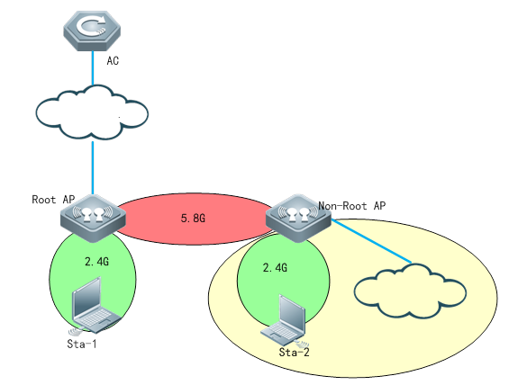
Notes
3. Wlan forwarding mode should be configured as centralized forwarding mode.
2. The ip address of root side and non-root side should in the same subnet
3. Non-root AP needs to establish the capwap tunnel with AC after bridging with the root AP
3. In this topology, the dhcp pool of AP and STA are on AC
II. Configuration Steps
【Controller】
3.1 Make sure that Root AP has established capwap tunnel with AC, verify by following command in controller:
Ruijie#sh capwap state
CAPWAP tunnel state, 1 peers, 1 is run:
Index Peer IP PortState
1 110.10.10.10 5246 Run
3.2 Configure Root-AP by using following command in controller:
AC(config)#wlan-config 100 wds-test-root ------>configure a special ssid for wds
AC(config-wlan)#exit
AC(config)#wlan-config 200 wds-test-2.4G------>Configure assid for 2.4g signal cover
AC(config-wlan)#exit
AC(config)#vlan 100 ------>Configure vlan for wds AP
AC(config-vlan)#exit
AC(config)#vlan 200 ------>Configure vlan for clients
AC(config-vlan)#exit
AC(config)#int vlan 100 ------>Configure dhcp pool for wds AP
AC(config-if-VLAN 100)#ip address 90.0.100.254 255.255.255.0
AC(config-if-VLAN 100)#exit
AC(config)#int vlan 200 ----->Configure dhcp pool for clients
AC(config-if-VLAN 200)#ip address 90.0.200.254 255.255.255.0
AC(config-if-VLAN 200)#exit
AC(config)#ip dhcp pool vlan-100
AC(dhcp-config)#network 90.0.100.0 255.255.255.0
AC(dhcp-config)#default-router 90.0.100.254
AC(dhcp-config)#option 138 ip 10.10.10.10
AC(dhcp-config)#exit
AC(config)#ip dhcp pool vlan-200
AC(dhcp-config)#network 90.0.200.0 255.255.255.0
AC(dhcp-config)#default-router 90.0.200.254
AC(dhcp-config)#dns-server 192.168.58.110
AC(dhcp-config)#exit
AC(config)#service dhcp ----->enable dhcp service
AC(config)#ap-group wds ---------> configure a new ap-group to associate the wlan-id and vlan
AC(config-group)#interface-mapping 100 100 radio 2
AC(config-group)#interface-mapping 200 200 radio 1
AC(config-group)#exit
AC(config)#ap-config ap630 -------> configure the AP which needs to be set as Root-AP in WDS
AC(config-ap)#ap-group wds
AC(config-ap)#station-role root-bridge bridge-wlan 1 radio 2
AC(config-ap)#end
AC#write
【Non-AP】
Shutdown the port on POE switch which connected to Non-AP. It's very important. It will help to prevent looping after change the AP to WDS mode.
3.3 Change AP to fat-mode
Ruijie#conf
Ruijie#(config)ap-mode fat
3.4 Connect AP (with ip add 192.168.110.1), and run the following command in this AP:
Ruijie#conf
Ruijie(config)#int dot11radio 2/0
Ruijie(config-if-Dot11radio 2/0)#station-role non-root-bridge
Ruijie(config-if-Dot11radio 2/0)#parent ssid wds-test-root ------> bridge SSID
Ruijie(config-if-Dot11radio 2/0)#wds pre-config create
Ruijie(config-if-Dot11radio 2/0)#exit
3.5 Change the AP to fit mode
Ruijie#conf
Ruijie#(config)ap-mode fit ----->change AP to fit mode, then ap will reload automatically, the wds will be setted up successfully.
Press RETURN to get started
*Jan 1 00:00:31: %LINK-3-UPDOWN: Interface WBI 2/0, changed state to up.
*Jan 1 00:00:32: %LINK-3-UPDOWN: Interface GigabitEthernet 0/2, changed state to down.
*Jan 1 00:00:32: %LINEPROTO-5-UPDOWN: Line protocol on Interface GigabitEthernet 0/2, changed state to down.
*Jan 1 00:00:32: %LINEPROTO-5-UPDOWN: Line protocol on Interface Dot11radio 1/0, changed state to up.
*Jan 1 00:00:32: %LINEPROTO-5-UPDOWN: Line protocol on Interface Dot11radio 2/0, changed state to up.
*Jan 1 00:00:32: %LINEPROTO-5-UPDOWN: Line protocol on Interface BVI 1, changed state to up.
*Jan 1 00:00:33: %LINEPROTO-5-UPDOWN: Line protocol on Interface WBI 2/0, changed state to up.
*Jan 1 00:00:41: %CAPWAP-6-STATE_CHANGE: Capwap discovery state changed, from <IDLE> to <DISC>
*Jan 1 00:00:47: %DHCP_CLIENT-6-ADDRESS_ASSIGN: Interface BVI 1 assigned DHCP address 10.1.1.15, mask 255.255.255.0.
Ruijie#ping 10.1*Jan 1 00:00:56: %CAPWAP-6-STATE_CHANGE: Capwap discovery state changed, from <DISC> to <SELECT>
*Jan 1 00:00:56: %CAPWAP-6-STATE_CHANGE: Capwap discovery state changed, from <SELECT> to <SUCCESS>
*Jan 1 00:00:56: %CAPWAP-6-STATE_CHANGE: (peer - 1) [10.10.10.10] capwap state changed, from <Idle> to <Join>
*Jan 1 00:00:56: %CAPWAP-6-STATE_CHANGE: (peer - 1) [10.10.10.10] capwap state changed, from <Join> to <Configure>
*Jan 1 00:00:56: %CAPWAP-6-STATE_CHANGE: (peer - 1) [10.10.10.10] capwap state changed, from <Configure> to <Data Check>
*Jan 1 00:00:56: %CAPWAP-6-STATE_CHANGE: (peer - 1) [10.10.10.10] capwap state changed, from <Data Check> to <Run>
*Jan 1 00:00:56: %CAPWAP-5-PEER_NOTIFY_UP: Peer <10.10.10.10: 5246: 1> UP.
3.6 After the NON-ROOT is online, it can be distributed all relevant configuration by AC
AC(config)#wlan-config 2 WDS-NONROOT-2.4
AC(config)#ap-group NONROOT
AC(config-group)#interface-mapping 2 200 radio 1 ap-wlan-id 1
AC(config)#ap-config 1414.4bc2.3156
AC(config-ap)#ap-group NONROOT
III. Verification
3.1 Check the bridge status on wlan controller
AC#show ap-config wds-bridge summary
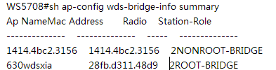
AC#show ap-config wds-bridge-info AP630-ROOT radio 2
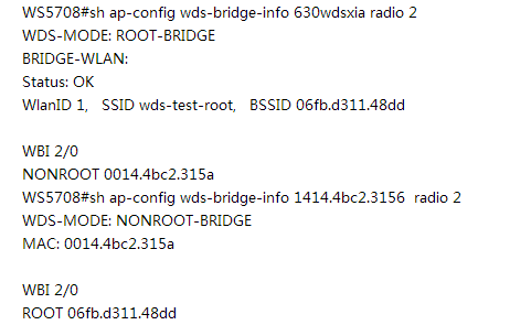
3.2 Check the bridge status on Root AP and Non-root AP.
AP630-ROOT#show dot11 wds-bridge-info 2/0
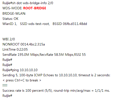
AP630-NONROOT#show dot11 wds-bridge-info 2/0
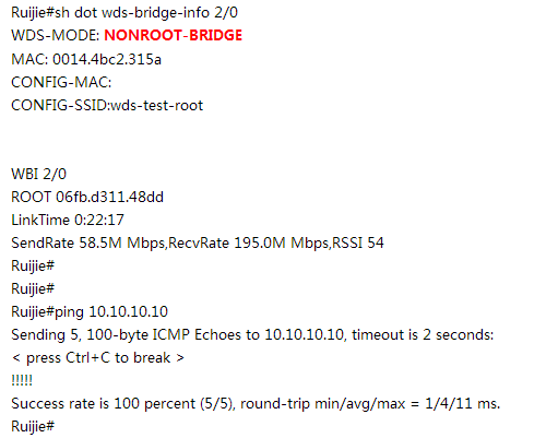
3.10.2 FAT AP
3.10.2.1 Point-to-Point Structure
Overview
Point-to-Point Structure
Since wireless devices are connected to each other, this structure is suitable for a network connecting two fixed points. The network topology is shown below:
Root Bridge + one Non-root Bridge
The wired interface of the root bridge is connected to the wired network, and its wireless interface is connected to the non-root bridge; The wireless interface of the non-root bridge is connected to the root bridge, and its wired interface is connected to the wired network; Two separate wired networks are connected in a wireless manner through the wireless bridging between the root bridge and the non-root bridge.
I. Network Topology
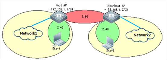
Notes
3. In FAT AP WDS scene, bridging WLAN need to be in OPEN authentication.
3. FAT AP can support 2 bridging ways, mac-address and ssid.The following configuration will take mac-address bridging for example.
3. In AP630 B8 version or later, it can support WDS encryption, but only RSN's and WPA's AES encryption.It doesn't support Tkip encryption.
3. If the distance of wireless transmission in WDS is over 1000m, you need to add a command:
interface Dot11radio 2/0
peer-distance 4000 ------>actual distance is 2000m
Please set the distance to a larger value (2-3 times the actual distance)
II. Configuration Steps
【ROOT-AP】
3. Create bridging VLAN
AP-1(config)#vlan 10
AP-1(config-vlan)#exit
3. Configure bridging WLAN-ID
AP-1(config)#dot11 wlan 1
AP-1(dot11-wlan-config)#ssid ruijie-test
3. Configure radio interface
AP-1(config)#interface dot11radio 2/0
AP-1(config-if-Dot11radio 2/0)#encapsulation dot1Q 10 ----->encapsulation vlan
AP-1(config-if-Dot11radio 2/0)#radio-type 802.11a ----->set radio 5.8G
AP-1(config-if-Dot11radio 2/0)#channel 149 ----->set channel 149
AP-1(config-if-Dot11radio 2/0)#chan-width 40
AP-1(config-if-Dot11radio 2/0)#station-role root-bridge bridge-wlan 1 ----->set ap as root-ap
AP-1(config-if-Dot11radio 2/0)#wlan-id 1 ----->SSID mapping
4. Check BSSID
AP-1#show dot11 mbssid
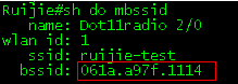
3. Configure AP bvi interface
AP-1(config)#interface bvi 10
AP-1(config-if-BVI 10)#ip address 192.168.1.254 255.255.255.0
6. Configured inteface
AP-1(config)#interface gigabitEthernet 0/1
AP-1(config-if-GigabitEthernet 0/1)#encapsulation dot1Q 10
3. Enable AP wireless broadcast
AP-1(config)#data-plane wireless-broadcast enable
3. Configure ssid for coverage
AP-1(config)#dot1 wlan 2 ----->create WLAN
AP-1(dot11-wlan-config)#ssid ruijie-wds-test ----->create ssid
AP-1(dot11-wlan-config)#exit
AP-1(config)#vlan 20 ----->creat Vlan
AP-1(config-vlan)#exit
AP-1(config)#int dot11radio 1/0.1
AP-1(config-subif-Dot11radio 1/0.1)#encapsulation dot1Q 20 ----->configure radio interface encapsulation vlan
AP-1(config-subif-Dot11radio 1/0.1)#exit
AP-1(config)#int dot11radio 1/0
AP-1(config-if-Dot11radio 1/0)#wlan-id 2
【Non-ROOT AP】
3. Creat bridging VLAN
AP-2(config)#vlan 10
AP-2(config-vlan)#exit
3. Configure radio
AP-2(config)#interface dot11radio 2/0
AP-2(config-if-Dot11radio 2/0)#encapsulation dot1Q 10 ----->encapsulation vlan
AP-2(config-if-Dot11radio 2/0)#station-role non-root-bridge ----->set AP role as non-root bridge
AP-2(config-if-Dot11radio 2/0)#parent mac-address 061a.a97f.1114 ----->set BSSID,and you can use "parent ssid xxxx" to match the SSID
3 Configure AP interface BVI
AP-2(config)#interface bvI 10
AP-2(config-if-BVI 10)#ip address 192.168.1.253 255.255.255.0
3. Enable AP wirless broadcast
AP-2(config)#data-plane wireless-broadcast enable
3. Configure ssid for coverate
AP-1(config)#dot1 wlan 2 ----->create WLAN
AP-1(dot11-wlan-config)#ssid ruijie-wds-test ----->create ssid
AP-1(dot11-wlan-config)#exit
AP-1(config)#vlan 20 ----->creat Vlan
AP-1(config-vlan)#exit
AP-1(config)#int dot11radio 1/0.1
AP-1(config-subif-Dot11radio 1/0.1)#encapsulation dot1Q 20 ----->configure radio interface encapsulation vlan
AP-1(config-subif-Dot11radio 1/0.1)#exit
AP-1(config)#int dot11radio 1/0
AP-1(config-if-Dot11radio 1/0)#wlan-id 2
III. Verification
Check bridging state
AP-1#show dot1 associations all-client
RADIO-ID WLAN-IDADDRAID CHAN RATE_DOWN RATE_UP RSSI ASSOC_TIME IDLE TXSEQ RXSEQ ERP STATE CAPS HTCAPS
2100:14:4b:6f:b8:361149 144.5M144.5M600:00:32 15565535 0x00x3 Es S
AP-1#ping 192.168.1.253
Sending 5, 100-byte ICMP Echoes to 192.168.1.10, timeout is 2 seconds:
< press Ctrl+C to break >
!!!!!
Success rate is 100 percent (5/5), round-trip min/avg/max = 2/11/28 ms.
Ruijie#show dot11 wds-bridge-info 2/0
WDS-MODE: ROOT-BRIDGE
BRIDGE-WLAN:
Status: OK
WlanID 1, SSID ruijie-test, BSSID 061a.a97f.1114
WBI 2/0
NONROOT 0014.4b6f.b836
LinkTime 0:00:47
SendRate 130.5M Mbps, RecvRate 133.5M Mbps, RSSI 60
3.10.2.2 Point-to-Multipoint Structure
Scenario
Point-to-Multipoint Structure
Since wireless devices are connected from one point to multiple points, this structure is suitable for a network with a central point and multiple remote points. The network topology is shown below:
Root Bridge + multiple Non-root Bridges
The root bridge serves as the root node, with its wireless interfaces being connected multiple non-root bridges.
The non-root bridges serve as leaf nodes, with their wireless interfaces being connected to the root bridge and wired interface to the designated wired network.
I. Requirements
Root AP and non-root AP need to be in the same subnet. And please make sure the model of root AP and non-root AP are the same.
II. Network Topology
Non-root AP Root AP Non-root AP
3.168.1.253 255.255.255.0 192.168.1.254 255.255.255.0 192.168.1.252 255.255.255.0
AP-2 (((( AP-1 )))) AP-3
III. Configuration Steps
Root-AP
3. Create a vlan for bridge
AP-1(config)#vlan 10
AP-1(config-vlan)#exit
3. Configure bridge WLAN
AP-1(config)#dot11 wlan 1
AP-1(dot11-wlan-config)#ssid ruijie-test
3. Configure radio for WDS
AP-1(config)#interface dot11radio 2/0
AP-1(config-if-Dot11radio 2/0)#encapsulation dot1Q 10 ----->encapsulate vlan
AP-1(config-if-Dot11radio 2/0)#station-role root-bridge bridge-wlan 1 ----->Radio mode Root-bridge and binding WLAN 1
AP-1(config-if-Dot11radio 2/0)#wlan-id 1
3. Verify wlan signal and BSSID
AP-1#show dot11 mbssid
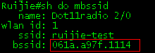
3. Configure BVI interface
AP-1(config)#interface bvI 10
AP-1(config-if-BVI 10)#ip address 192.168.1.254 255.255.255.0
Non-Root (AP2 and AP3)
3. Create a vlan for bridge
AP-2(config)#vlan 10
AP-2(config-vlan)#exit
3. Configure radio for WDS
AP-2(config)#interface dot11radio 2/0
AP-2(config-if-Dot11radio 2/0)#encapsulation dot1Q 10
AP-2(config-if-Dot11radio 2/0)#station-role non-root-bridge ----->Radio mode non-root-bridege
AP-2(config-if-Dot11radio 2/0)#parent mac-address 061a.a97f.1114 ----->Binding the Root-bridge BSSID(You can see this by step 4 on Root-AP configuration)
Or
AP-2(config-if-Dot11radio 2/0)#parent ssid ruijie-test ----->Binding the WDS SSID
(ruijie-test was configured on Root-AP step 2)
3. Configure BVI interface
AP-2(config)#interface bvI 10
AP-2(config-if-BVI 10)#ip address 192.168.1.253 255.255.255.0
3. Configure physical interface
AP-2(config)#interface gigabitEthernet 0/1
AP-2(config-if-GigabitEthernet 0/1)#encapsulation dot1Q 10
IV. Verification
On Root side
AP-1#show dot11 wds-bridge-info 2/0
WDS-MODE: ROOT-BRIDGE
BRIDGE-WLAN:
Status: OK
WlanID 1, SSID ruijie-test, BSSID 061a.a97f.1114 ----->AP-1 BSSID
WBI 2/0
NONROOT 0014.4b6f.b836 ----->AP-2 MAC address
LinkTime 0:00:47
SendRate 130.5M Mbps, RecvRate 133.5M Mbps, RSSI 60
WBI 2/1
NONROOT 0a25.d311.48ca ----->AP-3 MAC address
LinkTime 0:00:47
SendRate 130.5M Mbps, RecvRate 133.5M Mbps, RSSI 60
Non-Root side
Ruijie#sh dot wds-bridge-info 2/0
WDS-MODE: NONROOT-BRIDGE
MAC: 0014.4b6f.b836 ----->AP-2 MAC address
CONFIG-MAC:
CONFIG-SSID:wds-test-root
WBI 2/0
ROOT 061a.a97f.1114 ----->AP-1 BSSID
LinkTime 0:00:47
SendRate 58.5M Mbps, RecvRate 195.0M Mbps, RSSI 54
Ping testing
AP-1#ping 192.168.1.253 -----> AP-2 ip address
Sending 5, 100-byte ICMP Echoes to 192.168.1.10, timeout is 2 seconds:
< press Ctrl+C to break >
!!!!!
Success rate is 100 percent (5/5), round-trip min/avg/max = 2/11/28 ms.
AP-1#ping 192.168.1.252 -----> AP-3 ip address
Sending 5, 100-byte ICMP Echoes to 192.168.1.252, timeout is 2 seconds:
< press Ctrl+C to break >
!!!!!
Success rate is 100 percent (5/5), round-trip min/avg/max = 1/7/31 ms.
3.10.3 FAQ
3.10.3.1 How many bridges does AP630 support?
One root AP supports four none-root AP.
3.10.3.2 Is asso-rssi supported in a bridging environment?
No currently. The processing method in bridging mode is different from that when an ordinary terminal is connected to the underlying layer. The asso-rssi function is applicable for wireless users in normal access mode.
3.10.3.3 How to clear non-root AP configurations?
When the AP is online, run the following command:
ap-config xx
station-role root-ap radio 2
Or
ap-config xx
wds pre-config delete
The command must be run when the AP is online.
3.10.3.4 What are precautions for multi-hop bridging?
In multi-hop bridging mode, to guarantee the bridging link quality, channels for each of hops must be different.
For example, set channel 60 for the first hop, channel 100 for the second hop, and channel 149 for the third hop.
3.10.3.5 What is the signal strength requirement to guarantee the bridging link and video transmission quality?
Use the multi-hop bridging scenario in AP630 series products as an example.
The bridging uplink of the root bridge is called as the main link. To ensure the main link stability, the uplink RSSI must be at least 30. The link between the root bridge and a non-root bridge is called as a single link. To ensure the single link stability, the uplink RSSI must be at least 25. If the signal strength is lower than the specified value, adjust or change the AP location, to avoid that the video cannot be transmitted due to too low bridging performance caused by weak signal.
3.10.3.6 How to fix when modification to the non-root AP do not take effect on the AC?
All the commands for modifying the non-root bridge configuration take effect only after the wds config commit command is run.
In ap-config mode, run the wds config [ clear | commit ] radio radio-id command. The parameters are described below:
clear: Clears WDS configuration that does not take effect.
commit: Commits WDS configuration that does not take effect. After the operation, the bridge is disconnected and then connected.
radio radio-id: Indicates the radio ID configured on the AC.
If the AP is in non-root mode, its radio enters the wds edit mode. At this time, most of wds commands do not take effect immediately. You can run the show ap-config wds-config command to display the configurations. After confirming that the configurations are correct, run this command to commit the modification.
3.10.3.7 Is local forwarding mode supported when fit AP630s are bridged? Can multiple VLANs be bridged transparently?
Yes. The root bridge AP and non-root bridge AP must bridge VLANs transparently (run the bridge-vlan x command in ap-config mode). Assuming vlanx and vlany are VLANs required by non-root APs, the configuration method is as follows:
ap-config root bridge ap name
bridge-vlan x
bridge-vlan y
exit
ap-config non-root bridge ap name
bridge-vlan x
bridge-vlan y
exit
3.11 Load Balance
I. Requirements
Enable even distribution of STAs on multiple APs in a load balancing group.
Notes
Load balancing is applicable only to STAs that are associated, but not to STAs that are disassociated. Therefore, after STAs are disassociated, the traffic difference between APs or the STA quantity difference may exceed the threshold.
Load balancing takes effect only on the same type of radios (2.4 GHz or 5 GHz). If the types of radios are different, load balancing is performed only when the AP reports that the STAs are capable of dual-band operation. Otherwise, the 2.4 GHz STAs may fail to be associated with 2.4 GHz radios when no STA is associated with 5 GHz radio.
After the traffic-based balancing group is configured to use the traffic information uploaded by APs, APs must upload the traffic information to the AC at a regular interval because the traffic only exists on APs and is not routed to the AC.
During this interval, the traffic information on the AC does not change. At this time, if the traffic between APs is not balanced, STAs cannot be associated with APs with heavy traffic until the APs upload the traffic information to the AC.
II. Network Topology
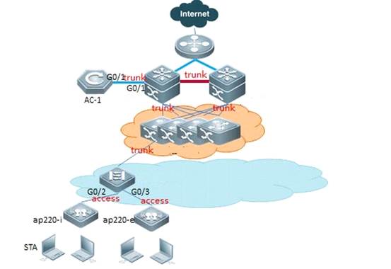
AP need to broadcast the same SSID signal in load-balance group.
III. Configuration Steps
3. Number-based
1) Create a number-based balancing group on the AC, named test1.
Ruijie(config)#ac-controller
Ruijie(config-ac)#num-balance-group create test1
2) Configure the load balance threshold
Ruijie(config-ac)#num-balance-group num test1 10 -----> when the difference of more than 10 STAs on APs, the AP which carries more users will not response new associations.
3) Add APs to the load balance group
Ruijie(config-ac)#num-balance-group add test1 ap320-1 ---->put AP named ap320-i into load balance group
Ruijie(config-ac)#num-balance-group add test1 ap320-2
4) Configure the maximum times of load balancing when STA associates failure
Ruijie(config-ac)#sta-balance num-limit enable
Note: It is necess to configure the maximum times shown as above in case the STA could not connect to the network successfully.
3. Traffic-based
1) Create a flow-based balancing group on the AC, named flow_huiyi
Ruijie(config)#ac-controller
Ruijie(config-ac)#flow-balance-group create flow_huiyi
2) Configure the load balance threshold
Ruijie(config-ac)#flow-balance-group flow flow_huiyi 4---->The default value is 5%. The percentage baseline is 10 Mbps by default.
3) Add APs to the load balance group
Ruijie(config-ac)#flow-balance-group add flow_huiyi ap220-1
Ruijie(config-ac)#flow-balance-group add flow_huiyi ap220-2
IV. Verification
3. Number-based
1) Use "show ac-config num-balance summary" on AC to check load balance state.
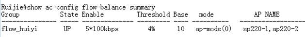
2) Use "show ap-config summary" on AC, check the number of STAs on each AP
3. Traffic-based
1) Use "show ac-config num-balance summary" on AC to check load balance state.
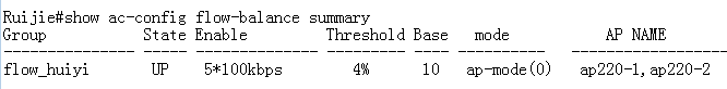
3.11.1 FAQ
3.11.1.1 How to View the Flow Balancing Group
Run the show ac-config flow-balance summary command to display the flow balancing group.
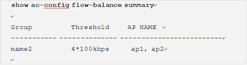
3.11.1.2 How to enable the flow-based load Balancing in local forwarding scenario?
In local forwarding mode, you can run the following command to enable flow balancing:
Ruijie(config-ac)#flow-balance-group radio-flow ?//Indicates the flow information of the flow balancing group reported by AP.
WORD Flow balance group name
Data packets in local forwarding mode do not pass through the AC and thus the AC cannot get the flow information. Load balancing must be judged by the traffic information reported by AP.
3.11.1.3 How many load balancing groups can an AC support now?
Up to 80 number-based balancing groups and 80 flow-based balancing groups.
3.11.1.4 How many APs at most can each load balancing group support?
3.
3.11.1.5 How to enable load balancing between AP radios on AC?
Under AP-config mode:
inter-radio-balance flow-balance enable //Based on flow
inter-radio-balance num-balance enable //Based on the number of users
You can configure the inter-radio load balancing parameters (optional) on AC based on actual requirements during network optimization.
Run the inter-radio-balance flow-balance dual-band enable-load en-num threshold thrs-num command to configure the enabling threshold of flow-based load balancing between radios of different bands. The lower the threshold, the easier the flow balancing can be enabled and the more even the flow is allocated.
Run the inter-radio-balance flow-balance same-band enable-load en-num threshold thrs-num command to configure the enabling threshold of flow-based load balancing between radios of same band. The lower the threshold, the easier the flow balancing can be enabled and the more even the flow is allocated.
Run the inter-radio-balance num-balance dual-band enable-load en-num threshold thrs-num command to configure the enabling threshold of number-based load balancing between radios of different bands. The lower the threshold, the easier the flow balancing can be enabled and the more even the flow is allocated.
Run the inter-radio-balance num-balance same-band enable-load en-num threshold thrs-num command to configure the enabling threshold of number-based load balancing between radios of same band. The lower the threshold, the easier the flow balancing can be enabled and the more even the flow is allocated.
3.12 RIPT
Overview
The Remote Intelligent Perceptive Technology (RIPT) is also known as the smart AP technology. As a wireless network edge device (as compared with an AC), the smart AP can perceive its connection with the AC and take over external provision of wireless networks seamlessly once connection fails. The wireless RIPT solution can be deployed in enterprise branch networks for the availability and sustainability of inter-WAN networks between the AC and APs in case of faults. It can also be deployed in a Wireless Local Area Network (WLAN) network to reduce reliance on ACs and improve its availability.
RIPT supports below two scenarios:
3. In 802.1x authentication scenario, we configure a escape-SSID in advance. The escape-SSID is hidden and disabled when the CAPWAP tunnel between AP and AC is operational. Once the AP is disconnected from AC, the escape-SSID is enabled to provide local resource access for STAs. When the tunnel recovers, the escape-SSID is disabled. When the 802.1X authentication is enabled and the RIPT AP works in standalone mode, the STAs cannot access the network through the 802.1X authentication.
3. In Web authentication scenario, once the AP is disconnected from AC, STAs can access the network without authentication. When the tunnel recovers, the Web or MAB authentication is required again. When the Web or MAB authentication is enabled and the RIPT AP works in standalone mode, the STAs cannot access the network through the Web or MAB authentication. In this case, you can enable the Web authentication exemption function to provide network access for STAs.
I. Network Topology
None
II. Configuration Steps
In 802.1x authentication scenario
1, make sure you have done 802.1x authentication settings right, you are able to access the SSID, pass the authentication, and visit Internet & Intranet with local forwarding.
To enable local forwarding mode, as below,
Ruijie(config)#wlan-config 5 "802.1x"
Ruijie(config-wlan)# tunnel local
2, configure RIPT as below steps:
1) Configure escape SSID
Ruijie(config)#wlan-config 10 "escape SSID"
Ruijie(config-wlan)#tunnel local
Ruijie(config-wlan)# enable-ssid at-capwap-down
2).Enable ript under AP group configuration mode
Ruijie(config)#ap-group default
Ruijie(config-group)#ript enable
In Web authentication scenario
1, make sure you have done web authentication settings right, you are able to access the SSID, pass the authentication, and visit Internet & Intranet with local forwarding.
To enable local forwarding mode, as below,
Ruijie(config)#wlan-config 15 "web authentication"
Ruijie(config-wlan)# tunnel local
2, configure RIPT as below steps:
1). Enable "free web authen" under wlan-config mode
Ruijie(config)#wlan-config 15 "web authentication"
Ruijie(config-wlan)# free-webauth at-capwap-down
2) Enable ript under AP group configuration mode
Ruijie(config)#ap-group default
Ruijie(config-group)#ript enable
III. Verification
3. To display RIPT status, execute command "show ap-config summary ript-enable"
Ruijie#show ap-config summary ript-enable
AP Name IP Address Mac Address ript-enable State
-------------------------- --------------- -------------- ----------- -----
ap1 172.18.55.73 1414.4b54.0000YY Run
3. Simulate AC down by unplug network cable, power off (it is not applicable to administratorly shutdown port on AC).
a. To test 802.1x authentication ript scenario, connect SSID "escape SSID", without authentication, you are able to visit Internet & Intranet
b. To test web authentication ript scenario, connect SSID "web authentication", without authentication, you are able to visit Internet & Intranet
Note: If AC is DHCP Server that assign IP address to wireless users, then wireless user will no longer obtain IP address once AC is down. Therefore, do not set DHCP server for wireless user on AC in RIPT scenario.
3.13 NAT
I. Network Topology
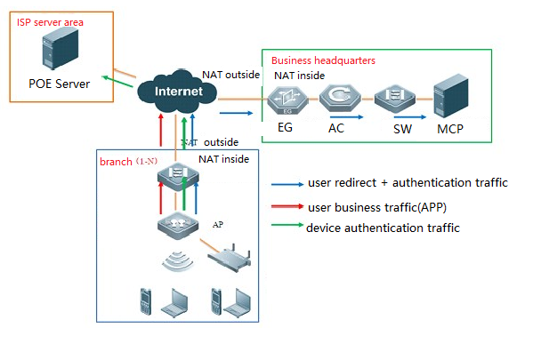
II. Configuration Steps
3. Configure DHCP pool for intranet users
Ruijie(config)#ip dhcp pool sta
Ruijie(dhcp-config)#network 192.168.1.0 255.255.255.0
Ruijie(dhcp-config)#dns-server 8.8.8.8
Ruijie(dhcp-config)#default-router 192.168.1.1
2. Configure ACL match intranet users' traffic
Ruijie(config)#ip access-list standard 1
Ruijie(config-std-nacl)#10 permit any
3. Configure IP address on the interface and set it as outside NAT interface
Ruijie(config)#interface GigabitEthernet 0/1
Ruijie(config-if-GigabitEthernet 0/1)# ip address 100.168.12.200 255.255.255.0
Ruijie(config-if-GigabitEthernet 0/1)#ip nat outside
3. Configure IP address on BVI interface 1 and set is as inside NAT interface
Ruijie(config)#interface BVI 1
Ruijie(config-if-BVI 1)#ip address 192.168.1.1 255.255.255.0
Ruijie(config-if-BVI 1)# ip nat inside
3. Configure address translation table
Ruijie(config)#ip nat inside source list 1 interface GigabitEthernet 0/1 overload
6. Configure default route pointing to gateway
Ruijie(config)#ip route 0.0.0.0 0.0.0.0 100.168.12.1
III. Verification
Intranet users are able to access the Internet.
3.14 URL Audit
I. Network Topology
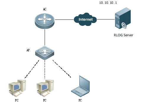
II. Configuration Steps
3. In manager forwarding mode, enable URL Auditing in global configuration mode
Ruijie# configure terminal
Ruijie(config)# url-rule audit-default-enable
Ruijie(config)# end
2. In local forwarding mode, enable URL Auditing in ap-config mode or ap-group mode
Ruijie# configure terminal
Ruijie(config)#ap-config all ----->configure all AP
Ruijie(config- ap)# url-rule audit-default-enable
Ruijie(config- ap)# end
III. Verification
Check the audited URL information using "show content-audit statistics brief" command.
In centralized forwarding mode, execute the command on AC. In local forwarding mode, execute the command on AP.
WS5708#show content-audit statistics brief
audit-total-number:22
id relate-user ap-name audit-time action key-type
---------- ---------------- ---------------- ------------------- ------ ----------------------------
22 172.17.0.2 ap320-F4 2014-11-10 16:09:09 permit url-host: blmobile.3g.qq.com
21 172.17.0.2 ap320-F4 2014-11-10 16:09:08 permit url-host: blmobile.3g.qq.com
20 172.17.0.2 ap320-F4 2014-11-10 16:09:02 permit url-host: m.baidu.com
19 172.17.0.2 ap320-F4 2014-11-10 16:09:02 permit url-host: ucs1.zc.ucweb.com:8080
18 172.17.0.2 ap320-F4 2014-11-10 16:08:55 permit url-host: cgi.connect.qq.com
17 172.17.0.2 ap320-F4 2014-11-10 16:08:53 permit url-host: appsupport.qq.com
This table can only contain 50 records. Use "clear content-audit statistic" command to clear the current audit records.
3.15 PPSK
3.15.1 Overview
3. Private Pre-Shared Key (PPSK) authentication can be enabled on only one Wireless Local Area Network (WLAN).
3. One independent Wi-Fi key (8 characters) is generated for each user and can be used to connect only one terminal. When the first terminal logs in, the key is bound to the terminal's Media Access Control (MAC) address so that it can be used only on this terminal. Authentication fails if you enter this key on other terminals.
3. A maximum of 1,500 keys can be generated for one user.
3.15.2 Scenario
| Employee Type |
Number of Employees |
Number of Keys Assigned to Each Account |
Total |
| Local |
121 |
3 |
363 |
| Non-local |
30 |
2 |
60 |
3.15.3 Implementation Steps
3.15.3.1 Upgrade
Upgrade the access controller (AC) and access point (AP) to the latest firmware versoin.
3.15.3.2 Enabling the PPSK
On the Web page, choose Network > WiFi/WLAN, select WPA/WPA2-PSK, and select Enable PPSK.
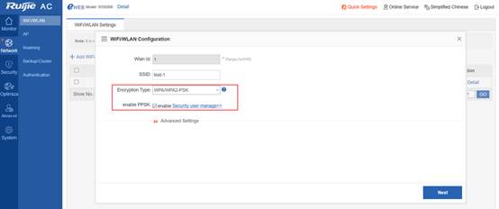
3.15.3.3 PPSK Account Management
On the Web page, choose Security > Security user manage. The following figure shows the effect of importing user names.
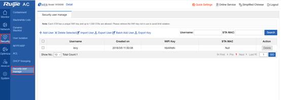
3.15.3.3.1 Adding a User
Click Add User. The following dialog box is displayed. Enter the user name. A random 8-character key is automatically generated.
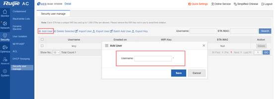
3.15.3.3.2 Adding Users in Batches
Click Batch Add User. The following dialog box is displayed. Download a template and enter user names.
The following figure shows a template for batch importing (user_template).

Note: User names are imported in the table from top to bottom. To display them in alphabetic order with identical user names next to each other, you need to rank them first because they cannot be ranked on the Security user manage page.
3.15.3.3.3 Exporting a Key
After user names are added or imported in batches, keys are automatically generated for all accounts. To export and assign the keys to all users, click Export Key to download the following table.

3.15.3.3.4 Backing up Data
The difference between Export User and Export Key is that the keys exported are displayed in cyphertext mode if you click Export User but in plaintext mode if you click Export Key.

3.15.3.3.5 Restoring Data
To restore data is to import backup data. Click Import User. The following dialog box is displayed.
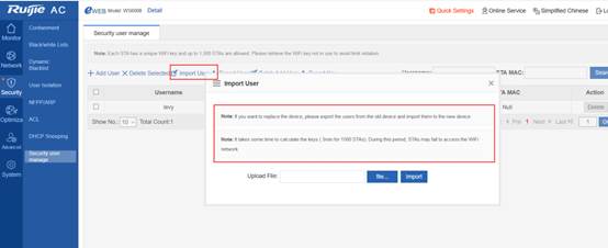
3.15.3.3.6 Searching an Account
If too many PPSK accounts are managed, you can find a user by entering the user name or MAC address.
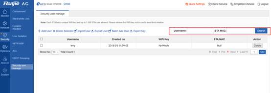
3.15.4 PPSK Configuration and Verification Under the Command Line
3.15.4.1 PPSK Configuration Under the Command Line
//Enter the user name. A PPSK is generated.
3.15.4.2 PPSK Verification Under the Command Line
Verify one PPSK account.
![]()
To check all PPSK accounts, display the number of current PPSK accounts and the number of accounts bound to MAC addresses.
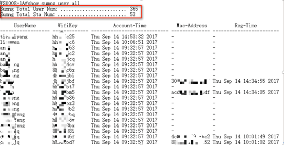
3.15.5 PPSK Verification
Create a user name lishaohuan. A random key dhbs2666 is generated. Enter the key to connect the PC to the Wi-Fi network.
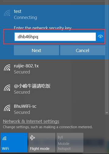
After PC authentication succeeds, the bound terminal MAC address displayed on the Security user manage page is the PC's MAC address.
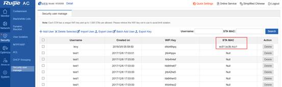
If you enter the same key on another terminal, authentication fails, as shown in the following figure.
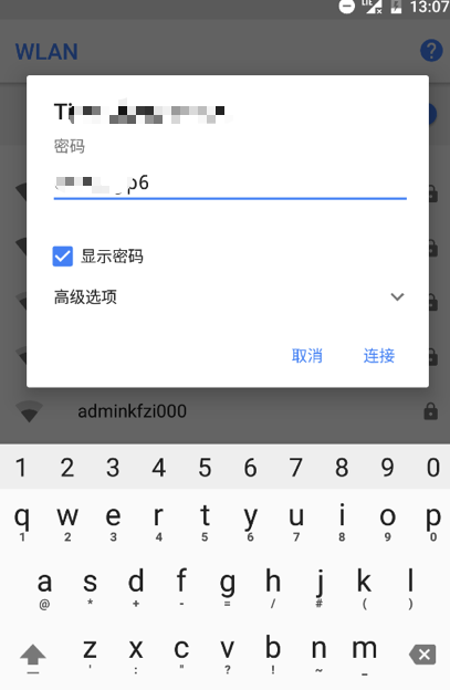
3.16 Bonjour Gateway
3.16.1 Overview
A Bonjour gateway manages clients and servers supporting Bonjour protocol to enable the application of Bonjour protocol to large-scale networks.
A Bonjour gateway has the following features.
Control the multicast DNS (mDNS) protocol packet traffic and reduce mDNS protocol packets on networks.
Support configuration of policies and manage services that can be used on clients.
Forward mDNS protocol packets of clients and servers across Virtual Local Area Networks (VLANs) and improve the usability of networks.
![]() The following describes the Bonjour gateway only.
The following describes the Bonjour gateway only.
3.16.2 Applications
| Application |
Description |
| In some cases, if the Bonjour gateway fails to obtain specified services requested by clients according to the Bonjour service resource capacity although the gateway receives query packets from the clients, query proxy and response forwarding are enabled. The Bonjour gateway will forward query packets. If response packets relating to the services are received, the gateway will add corresponding information to the Bonjour service resource capacity and forward response packets to the clients. Then response pickup can be enabled. |
3.16.2.1 Query Proxy and Response Forwarding
Scenario
As shown in the following figure, iPad, Apple TV, and Print are on different VLANs. iPad needs to obtain IP addresses of Apple TV and Print through the Bonjour gateway to communicate with Apple TV and Print.
Figure 6-1 Bonjour gateway network topology
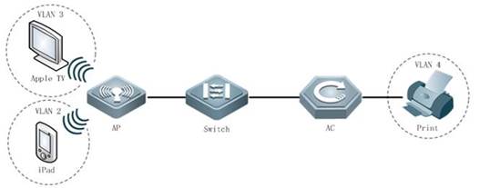
Deployment
3.16.2.2 Multimedia Gateway Disabling Preemption
Scenario
As shown in the following figure, iPad, Apple TV, and Print are on different VLANs. iPad needs to obtain IP addresses of Apple TV and Print through the Bonjour gateway to communicate with Apple TV and Print. Different terminals may use the screen projection feature of Apple TV simultaneously. In this case, preemption is enabled if the Bonjour gateway is disabled. However, preemption is disabled when the Bonjour gateway is enabled.
Figure 6-2 Bonjour gateway network topology
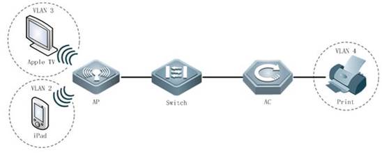
Deployment
3.16.2.3 Automatic Naming for the Multimedia Gateway Server
Scenario
As shown in the following figure, iPad, Apple TV, and Print are on different VLANs. iPad needs to obtain IP addresses of Apple TV and Print through the Bonjour gateway to communicate with Apple TV and Print. If multiple Apple TV devices exist on the network, they may share one name, which is confusing. Currently, devices can be automatically named in "name+IP address" mode to tell servers apart.
Figure 6-3 Bonjour gateway network topology
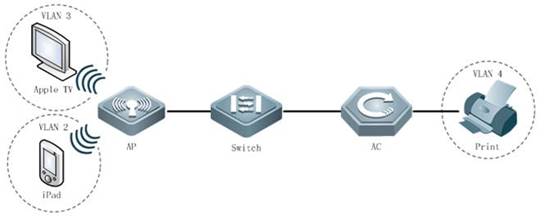
Deployment
A Bonjour gateway can process mDNS request packets received on the port and automatically name servers discovered only when the Bonjour gateway is enabled in global configuration mode.
3.16.3 Features
Basic Concepts
Bonjour
Apple names the mDNS-based open zero-configuration networking standards Bonjour. Devices using Bonjour automatically transmit their respective service information and listen to service information of other devices on networks, as if they were greeting each other. In this way, systems and service on Local Area Networks (LANs) can be detected easily without network administrators. Bonjour displays names of the devices and applications supporting mDNS protocol on LANs, and avoids device name repetition through mDNS.
Bonjour gateway
A Bonjour gateway manages clients and servers supporting Bonjour protocol to enable the application of Bonjour protocol to large-scale networks.
Overview
| Feature |
Description |
| A Bonjour gateway manages clients and servers supporting Bonjour protocol to enable the application of Bonjour protocol to large-scale networks. |
3.16.3.1 Bonjour Gateway
Working Principle
A Bonjour gateway manages clients and servers supporting Bonjour protocol to enable the application of Bonjour protocol to large-scale networks.
A Bonjour gateway has the following features.
Response pickup
On the network, servers send Bonjour response packets and notify supported services. Upon receipt of the response packets, the Bonjour gateway establishes a service resource capacity so that it can return response packets to the clients querying services in the capacity.
Query proxy and response forwarding
In some cases, if the Bonjour gateway fails to obtain specified services requested by clients according to the Bonjour service resource capacity although the gateway receives query packets from the clients, query proxy and response forwarding are enabled. The Bonjour gateway will forward query packets. If response packets relating to the services are received, the gateway will add corresponding information to the Bonjour service resource capacity and forward response packets to the clients. Then response pickup can be enabled.
Disabling screen preemption
Different terminals may use the screen projection feature of Apple TV simultaneously. In this case, preemption is enabled if the Bonjour gateway is disabled. However, preemption is disabled when the Bonjour gateway is enabled.
Automatic naming for servers
3.16.4 Configuration
| Configuration |
Description and Command |
|
|
|
||
| bonjour-gateway enable |
Enables the Bonjour gateway. |
|
|
|
||
| bonjour-gateway multicast |
Configures the threshold for returning response packets in multicast mode. |
|
|
|
||
| bonjour-gateway global-strategy |
Applies specified Bonjour policies in global configuration mode. |
|
| bonjour-gateway strategy |
Applies specified Bonjour policies in interface configuration mode. |
|
| bonjour-gateway strategy-mode |
Creates Bonjour policies. |
|
| sService -type |
Configures service rules. |
|
| service- vlan |
Configures VLANs on which query and response packets can be forwarded. |
|
|
|
service wired/wireless |
Configures wired/wireless discovery. |
|
|
||
| bonjour-gateway query enable |
Configuresautomatic Bonjour service query. |
|
| bonjour-gateway query interval |
Configures the interval for automatic Bonjour service query. |
|
3.16.4.1 Enabling the Bonjour Gateway
Configuration Effect
Enable the Bonjour gateway so that Bonjour protocol can be applied to large-scale networks.
Notes
The Bonjour gateway must be enabled on a Layer-3 interface.
Configuration Steps
Enable the Bonjour gateway.
Mandatory.
| Command |
bonjour-gateway enable |
| Parameter Description |
- |
| Defaults |
The Bonjour gateway is disabled. |
| Command Mode |
Global configuration mode or interface configuration mode |
| Usage Guide |
The multicast mode is enabled on all or specified Layer-3 interfaces so that multicast packets can be forwarded. |
Configuring the Threshold for Returning Response Packets in Multicast Mode
Optional.
Run the bonjour-gateway multicast command to configure the threshold for returning response packets in multicast mode.
| Command |
bonjour-gateway multicast number |
| Parameter Description |
number: Indicates the threshold for returning response packets in multicast mode, ranging from 1 to 64. |
| Defaults |
The threshold for returning response packets in multicast mode is 10. |
| Command Mode |
Global configuration mode |
| Usage Guide |
Run the bonjour-gateway multicast command to configure the threshold for returning response packets in multicast mode. Run the no bonjour-gateway multicast command to restore the default. By default, the threshold for returning response packets in multicast mode is 10. |
l
Verification
Run the show run command to check configurations for the Bonjour gateway.
Configuration Example
Enabling the Bonjour Gateway
| Scenario Figure 6-4 |
|
|
|
|
| Configuration Steps |
Enable the Bonjour gateway. |
|
|
|
|
|
|
| Verification |
Check whether the Bonjour gateway is enabled. ! |
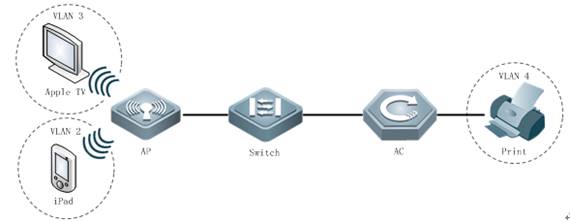
Common Errors
-
3.16.4.2 Configuring Bonjour Policies
Configuration Effect
Support configuration of Bonjour policies and manage services that can be used on clients.
Notes
N/A
Configuration Steps
Create a Bonjour policy.
Optional.
Run the bonjour-gateway strategy-mode command to create a Bonjour policy.
| Command |
bonjour-gateway strategy-mode name |
| Parameter Description |
name: Indicates the Bonjour policy name. |
| Defaults |
No Bonjour policies exist. |
| Command Mode |
Global configuration mode |
| Usage Guide |
Run the bonjour-gateway strategy-mode command to create a Bonjour policy. Run the no bonjour-gateway strategy-mode command to delete a Bonjour policy. By default, no Bonjour policies exist. A maximum of 1,000 Bonjour policies can be created on a device. |
Configuring Service Discovery Rules
Optional.
Run the service-type wired/wireless disable command to configure service discovery rules.
| Command |
service- [type typewired | wireless] [ ip ipv4-address | ipv6 ipv6-address | instance name ]disable |
| Parameter Description |
type: Indicates the service type. ipv4-address: Indicates the IPv4 address of the service. ipv6-address: Indicates the IPv6 address of the service. name: Indicates the instance name of the service. |
| Defaults |
No limit is set for service searching; that is, a client can find all services in both wired and wireless modes. |
| Command Mode |
bonjour-gateway configuration mode |
| Usage Guide |
Run the service-type wired/wireless disable command to configure service rules. Run the no service-type wired/wireless disable command to delete service rules. By default, no limit is set for service searching; that is, a client can find all services in both wired and wireless modes. |
Configuring Service Rules
Optional.
Run the service type command to configure service rules.
| Command |
service type type [ ip ipv4-address | instance name | disable ] |
| Parameter Description |
type: Indicates the service type. ipv4-address: Indicates the IPv4 address of the service. name: Indicates the service instance name. |
| Defaults |
No limit is set for service searching; that is, a client can find all services. |
| Command Mode |
bonjour-gateway configuration mode |
| Usage Guide |
Run the service type command to configure service rules. Run the noservice type command to delete service rules. By default, no limit is set for service searching; that is, a client can find all services. When the disable command is executed, services cannot be found. |
Configuring Service VLANs
Optional.
Run the service-vlan command to configure VLANs on which query and response packets can be forwarded. Apply specified Bonjour policies.
| Command |
service- vlan vlan-id-list [ access-vlan ] |
| Parameter Description |
vlan-id-list: Indicates the VLAN list. access-vlan: Forwards query and response packets on VLANs. |
| Defaults |
No query or response packets are forwarded. |
| Command Mode |
bonjour-gateway configuration mode |
| Usage Guide |
Run the service- vlan command to configure VLANs on which query and response packets can be forwarded. Run the no service- vlan command to delete configurations. By default, no query or response packets are forwarded. |
l
Applying Specified Bonjour Policies in Global Configuration Mode
Optional.
Run the bonjour-gateway global-strategy command to apply specified Bonjour policies on Layer-3 interfaces.
| Command |
bonjour-gateway global-strategy name |
| Parameter Description |
name: Indicates the Bonjour policy name. |
| Defaults |
No Bonjour policies are applied in global configuration mode. |
| Command Mode |
Configuration mode |
| Usage Guide |
Run the bonjour-gateway global-strategy command to apply specified Bonjour policies in global configuration mode. Run the no bonjour-gateway global-strategy command to cancel Bonjour policies in global configuration mode. By default, no Bonjour policies are applied in global configuration mode; that is, when the Bonjour gateway is enabled, only default service types are supported and can be discovered in both wired and wireless modes. |
Applying Specified Bonjour Policies
Optional.
Run the bonjour-gateway strategy command to apply specified Bonjour policies on Layer-3 interfaces.
| Command |
bonjour-gateway strategyname |
| Parameter Description |
name: Indicates the Bonjour policy name. |
| Defaults |
No Bonjour policies are applied on Layer-3 interfaces. |
| Command Mode |
Interface configuration mode |
| Usage Guide |
Run the bonjour-gateway strategy command to apply specified Bonjour policies on Layer-3 interfaces. Run the no bonjour-gateway strategy command to cancel Bonjour policies. By default, no Bonjour policies are applied on Layer-3 interfaces. |
l
Verification
Run the show run command to check configurations for the Bonjour gateway.
Configuration Example
Configuring Bonjour Policies
| Scenario |
See Figure 6-4. |
|
|
|
| Configuration Steps |
Configure Bonjour policies. |
|
|
|
|
|
|
| Verification |
Check whether the Bonjour gateway is enabled. ! Check whether Bonjour policies are configured. ! |
Common Errors
N/A
3.16.4.3 Automatic Bonjour Service Query
Configuration Effect
To enable response pickup, maintain the Bonjour service resource capacity. Enable automatic Bonjour service query to ensure the real-time performance of the Bonjour service resource capacity.
Notes
N/A
Configuration Steps
Configuring Automatic Bonjour Service Query
Optional.
Run the bonjour-gateway query enable command to configure automatic Bonjour service query.
| Command |
bonjour-gateway query enable |
| Parameter Description |
N/A |
| Defaults |
The automatic Bonjour service query feature is disabled. |
| Command Mode |
Global configuration mode |
| Usage Guide |
Run the bonjour-gateway query enable command to configure automatic Bonjour service query. Run the no bonjour-gateway query enable command to disable automatic Bonjour service query. By default, The automatic Bonjour service query feature is disabled. |
Configuring the Interval for Sending Query Packets to Discovered Services
Optional.
Configure the interval for sending query packets to discovered services.
| Command |
|
| Parameter Description |
number: Indicates the interval for sending query packets to discovered services, ranging from 5 to 600 seconds. |
| Defaults |
The interval for sending query packets to discovered services is 15 seconds. |
| Command Mode |
Global configuration mode |
| Usage Guide |
Run the bonjour-gateway query interval command to configure the interval for sending query packets to discovered services. Run the no bonjour-gateway query interval command to store the default. By default, the interval for sending query packets to discovered services is 15 seconds. |
l
Verification
Run the show run command to check configurations for the Bonjour gateway.
Configuration Example
Configuring Automatic Bonjour Service Query
| Scenario |
See Figure 6-4. |
|
|
|
| Configuration Steps |
Configure automatic Bonjour service query. |
|
|
|
|
|
|
| Verification |
Check whether automatic Bonjour service query is configured. ! |
Common Errors
-
3.16.5 Monitoring
| Description |
Command |
| Displays discovered Bonjour services. |
show bonjour-gateway service-database |
| Displays Bonjour statistics. |
show bonjour-gateway statistics |
| Displays Bonjour policies. |
show bonjour-gateway strategy-mode |
Debugging
![]() System resources are occupied when debugging information is output. Therefore, disable debugging immediately after use.
System resources are occupied when debugging information is output. Therefore, disable debugging immediately after use.
| Description |
Command |
| Debugs the Bonjour gateway errors. |
debug bonjour error |
| Debugs screen preemption for the Bonjour gateway. |
debug bonjour stamng |
3.17 Hierachical AC
3.17.1 Overview
3.17.1.1 Background
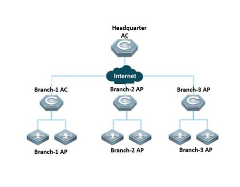
Hierarchical access controllers (ACs) provide a centralized management+distributed forwarding model (centralized control or distributed control is enabled on the control plane). As shown in the preceding figure, one headquarters AC and multiple branch ACs exist on the network. Normally a Wide Area Network (WAN), for example, the Internet, exists between the headquarters AC and branch ACs.
Headquarters AC: Access Point (AP) and AC versions and configurations can be assigned by the headquarters AC in centralized mode. The status of wireless APs and clients on the entire network can be displayed on the headquarters AC in centralized mode. Normally, branch ACs manage branch APs and stations (STAs). When branch ACs become abnormal, the headquarters AC takes over the job temporarily.
Branch AC: A branch AC is composed of standard ACs, all-in-one ACs (capable of routing and Deep Packet Inspection (DPI)), or wired/wireless integrated switches. Normally, branch ACs manage branch APs and stations (STAs). When branch ACs become abnormal, the headquarters AC takes over the job temporarily so that the network reliability can be improved.
In the following two scenarios, hierarchical ACs are needed.
Scenario 1: General education MetropolitanAreaNetwork (MAN): High-performance ACs are deployed for the Education Bureau, and small ACs (standalones) are deployed for middle and primary schools. The following describes requirements in the scenario.
High reliability
When branch ACs of middle and primary schools fail, branch APs can be connected to the center AC of the Education Bureau to ensure the availability of wireless networks.。
Easy management
Supporting unified upgrade: The center AC supports unified upgrade of branch ACs and APs. Multiple models of branch ACs and APs can exist.
Supporting unified authorization: Branch ACs of middle and primary schools and the center AC of the Education Bureau share one AP license so that no more licenses are needed.
Supporting unified configuration as well as hierarchical and rights-based management: As the Education Bureau manages schools in mandatory mode, it must be able to manage devices (ACs and APs) on the entire network in unified mode. However, in view of the heavy management workload, management rights can be delegated to schools for hierarchical and rights-based management. As only a few teachers in the general education system are well informationalized, if the management rights are completely delegated, schools cannot manage themselves well.
Supporting unified monitoring: You can check which branch ACs, APs, or terminals are online.
Supporting unified authentication: Authentication servers are deployed in the Education Bureau, and accounts are managed by these servers in centralized mode. Branch devices must be authenticated in the headquarters before they are connected to the network.
Supporting distributed authentication: Red-Giant Easy Security System (RG-ESS) is deployed in branches, and Red-Giant Identity & Policy Center (RG-IPC) is deployed in the headquarters. The mature solutions for distributed ESS+IPC deployment are supported.
Note: The user traffic is forwarded from the local Internet egress of a branch.
Scenario 2: Headquarters-branch wireless office network: High-performance ACs are deployed for the headquarters, and small ACs (standalones) are deployed for branches. The following describes requirements in the scenario.
Easy management
Supporting unified upgrade: See "Scenario 1".
Supporting unified authorization: See "Scenario 1".
Supporting unified configuration as well as hierarchical and rights-based management: Branches must apply specific configurations applied by the headquarters. For example, if ruijie-web signals must be released, branch devices are allowed to release other ruijie-xxx signals.
Supporting unified monitoring: You can check branch AC connections on the center AC and check connections between APs and STAs on branch ACs.
Supporting unified authentication: The headquarters manages in mandatory mode the wireless connection of branch devices. Accounts are managed by headquarters-authenticated servers in centralized mode. Branch devices must be authenticated in the headquarters before they are connected to the network. After authentication succeeds, the traffic is forwarded from the local Internet egress of the branch.
Supporting distributed authentication: RG-ESS is deployed in branches, and RG-IPC is deployed in the headquarters. The mature solutions for distributed ESS+IPC deployment are supported.
Note: The user traffic is forwarded from the local Internet egress of a branch.
Note: 1. The current release does not support unified configuration.
3.17.1.2 Components and Version
| Area |
Product Name |
Function |
Version |
Remarks |
| Branch |
Wireless AP |
Wireless forwarding path |
Later than V11.x B8 |
N/A |
| Power over Ethernet (PoE) switch |
PoE |
Unlimited |
N/A |
|
| Wireless AC |
Box wireless AP controller |
Office networks |
Supported by specific versions and models |
|
| Easy Gateway (EG) |
Gateway, Virtual Private Network (VPN), traffic control, and network address translation (NAT) |
Unlimited |
N/A |
|
| Eportal |
Portal server |
Unlimited |
Required for distributed authentication only |
|
| RG-ESS |
ESS |
Unlimited |
Required for distributed authentication only |
|
| Headquarters |
Wireless AP |
Wireless forwarding path |
Later than V11.x B8 |
N/A |
| PoE switch |
PoE |
Unlimited |
N/A |
|
| Wireless AC |
Box wireless AP controller or board-style (N18K) wireless AP controller |
Office networks |
Supported by specific versions and models |
|
| Gateway switch |
Gateway |
Unlimited |
N/A |
|
| EG |
Gateway, VPN, traffic control, and NAT |
Unlimited |
N/A |
|
| Eportal |
Portal server |
Unlimited |
N/A |
|
| SAM |
AAA server |
Unlimited |
N/A |
|
| RG-IPC |
IPC: RG-IPC is a control center of Red-Giant Security Management Platform (RG-SMP) and RG-ESS in distributed management mode. As a management center deployed in the management organization of the headquarters, RG-IPC manages RG-SMP and RG-ESS servers running in distributed management mode. It is capable of branch management and unified user management. |
Unlimited |
Required for distributed authentication only |
3.17.2 Preparation for Deployment
3.17.2.1 Device Selection
During deployment of hierarchical AC networks, a center AC bears unified upgrade, unified monitoring, and failure backup, which requires strong processing capabilities of the headquarters AC. Currently, the following models can serve as center ACs.
WS6816
WS6812
M8600E-WS-ED
M18000-WS-ED
The following models can serve as branch ACs. Low-end and mid-range models (including WS5708, WS6108, WS6008, WS6024, and M6000-WS) are adequate; high-end models (including WS6816, WS6812, M8600E-WS-ED, and M18000-WS-ED) are not required.
l WS5708
l WS6108
l WS6008
l WS6024
l M6000-WS
l WS6816
l WS6812
l M8600E-WS-ED
l M18000-WS-ED
How many branch ACs the network supports is determined by the following two conditions (for example, theoretically 128 branch ACs are supported in cold backup mode). If a center AC can manage a maximum of 4,000 APs and each branch AC has 1,000 APs, four branch ACs are supported. That is, only four branch ACs can be supported.
In cold backup mode, a maximum of 128 branch ACs are supported. In hot backup mode, a maximum of 32 branch ACs are supported. In hybrid mode, the value of "the number of hot backup branch ACs x 4 + the number of cold backup branch ACs" must be less than 128; therefore, the number of branch ACs supported is between 32 and 128.
The maximum number of APs to be managed by a center AC (the number of branch ACs + the number of all APs and STAs in the headquarters) or branch AC (the number of branch APs and STAs), the maximum number of APs to be configured, the maximum number of STAs to be managed, and the recommended number of STAs to be managed equal the maximum numbers of devices to be supported by corresponding products, respectively. For example, if the center AC is ws6812, as the maximum number of APs to be configured on ws6812 is 8,000, the maximum number of APs to be configured on the center AC is 8,000.
Note: The following describes the difference between cold and hot backup modes.
In hot backup mode, theoretically online users are completely unaware of failover because of uninterrupted data flows. New users can be authenticated and go online only after the failover, which lasts for 30 seconds.
In cold backup mode, online users are almost unaware of failover (theoretically, data flows are interrupted for no more than 30 seconds). New users can be authenticated and go online only after the failover, which lasts for 30 seconds.
In cold backup mode, a CAPWAP tunnel is built between each branch AP and each branch AC and between each branch AP and the center AC, respectively. However, between branch ACs and the center AC, only the data required for unified monitoring are backed up, and user entries are not backed up. When failover occurs, STAs need to be associated, apply for IP addresses, and be authenticated again. STAs like mobile phones automatically get associated and apply for IP addresses, which users are almost unaware of. STAs also automatically finish dot1x authentication or perception-free authentication, which users are almost unaware of. For non-perception-free Web authentication (which does not exist in reality), the authentication page is displayed again, and users need to enter the user name and password.
3.17.2.2 User IP Address Planning
In the following two scenarios, user IP address segments of centerand branch ACs need to be planned.
Wireless access authentication servers of branch ACs are deployed on the center AC and used for portal authentication. In this case, as portal authentication is based on IP addresses, there are requirements for IP addresses in deployment.
Despite independent wireless access authentication servers deployed on branch ACs, data of branch and center ACs are backed up, and portal authentication is used for wireless access. In this case, when branch ACs fail, the center AC takes overs wireless access authentication for branch ACs so that there are requirements for IP addresses in deployment.
In the preceding two scenarios, IP address segments of branch and center ACs need to be planned provided that IP address segments of branch and center ACs must not be overlapped.
3.17.2.3 License Planning
One of the advantages of deploying hierarchical ACs is that branch and center ACs can share the same licenses. When branch ACs fail, the center AC takes over the APs of branch ACs, in extreme cases, the total of center APs plus branch APs is the number of APs necessary for deploying hierarchical ACs. Therefore, you need to consider the demands of center and branch APs when purchasing AP licenses.
Licenses (including the default ones) of branch ACs are automatically synchronized to the headquarters AC. They are frozen for the branch ACs and will be unfrozen only when the branch ACs become abnormal and the headquarters AC needs to take over APs. However, the right of license use is reserved only for 7-14 days by default. Therefore, branch ACs must recover within 7-14 days; otherwise, branch APs have to occupy the licenses of the headquarters AC.
Licenses of a branch AC cannot be shared with other branch ACs, while licenses (including the default ones) of the center AC can be shared with branch ACs. When the center AC is disconnected, hierarchical ACs no longer exist and branch ACs become independent of each other (the right to use licenses of the center AC is also reserved only for 7-14 days by default). Therefore, AP licenses can be installed on the center AC, which will share the licenses with branch ACs.
3.17.2.4 Remote Interconnection Planning
For deployment of center ACs, the center AC must be able to remotely interconnect with each branch AC. The following solutions are available for remote interconnection.
Dedicated line: The center AC is connected with branch ACs through dedicated lines. In this case, the center AC and branch ACs form a large Local Area Network (LAN) where the center AC already interworks with branch ACs so that no special deployment is needed.
Mapping LAN addresses to WANs through NAT for interworking between branches and the headquarters: Mapping some LAN addresses to WANs through NAT is not allowed for office networks because it is not safe. In addition, currently all egress devices support IPSec VPN. Therefore, such deployment mode is not recommended.
3.17.2.5 Authentication Planning
Deployment authentication is one of the foundations for deployment of wireless networks. In hierarchical AC networking, two elements should be considered for deployment authentication.
Type of Wireless Access Authentication
Typical wireless access authentication includes WAP2-PSK, WPA2-802.1X, and Portal authentication.
WAP2-PSK: There are no special restrictions on deployment.
WAP2-802.1X: There are no special restrictions on deployment. To deploy the ip-valid feature of 802.1X, see "Section 2.2 User IP Address Planning". During the network planning, IP address segments of headquarters and branch ACs must not be overlapped.
Portal authentication: See "Section 2.2 User IP Address Planning". During the network planning, IP address segments of headquarters and branch ACs must not be overlapped.
Positions of Branch Authentication Servers
Two deployment models are available.
Deploying independent authentication servers in branches: In this model, branch ACs independently maintain authentication servers and accounts. In addition, accounts need to be synchronized between the center AC and branch ACs so that when branch ACs fail, the center AC can take over network access authentication servers. Accounts can be synchronized in two modes.
Manual synchronization
Deploy an AD domain on the authentication server as a database for authenticated accounts, and synchronize accounts through the AD domain. For details, see the Windows AD Domain Configuration Guide.
Deploy Ruijie IPC to synchronize accounts of the branch authentication servers (ESS) with accounts of the center authentication server (SMP). For details, see the ESS/IPC Configuration Guide.
Branch ACs using the center authentication servers: As authentication will affect wireless network access, this deployment mode is demanding on the reliability of links between branch ACs and the center AC. If branch ACs are not connected to the center AC through highly reliable links, such as dedicated lines or MANs, such deployment mode cannot be used. However, the following requirements must be met if you are determined to use the deployment mode.
Performance of the center authentication server: Performance of software and hardware should be considered. When a baseline is applied, the authentication server must be able to support online authentication for users of the center AC and all branch ACs. For details, see software and hardware specifications of the authentication server.
Reliability of servers: Servers must be highly reliable because they authenticate center and branch devices on networks. Uninterruptible Power Supply (UPS), server load balancing, and multi-server backup should be considered beforehand.
Account management: In this model, center devices maintain accounts of all branch devices, including avoiding account overlapping and changing.
3.17.2.6 WLAN Planning
One of the advantages of deploying hierarchical ACs is that when branch ACs fail, the center AC can take over branches and continues offering wireless network access services. For that purpose, wireless networks need to be planned for center and branch ACs.
Unified WLAN planning: Hierarchical ACs back up data of center and branch devices by using the backup technology to enable failover. Therefore, WLANs need to be planned for center and branch devices as if during hot backup deployment: AP groups, WLAN IDs, and Service Set Identifiers (SSIDs) must be consistent. This operation is reflected in hot backup configuration; that is, hot backup configuration for the center AC must be consistent with that for branch ACs. In this way, when branch ACs fail, the center AC can take over branches with the same configuration.
3.17.2.7 Bandwidth Consumption by Hierarchical ACs
The bandwidth consumed by hierarchical ACs is mainly used to back up user entries between branches and the headquarters.
Consumption of branch egress bandwidth: A branch AC authenticates no more than 32 online/offline users per second (for example, based on the specifications, the index of WS5708 authenticating online/offline users per second is 32/second).
In cold backup mode, each branch AC backs up one user and sends only one packet. As 32 packets are sent per second and the size of each packet is no more than 0.5 KB, no more than 16 KB of packets are sent per second.
In hot backup mode, each branch AC backs up one user and sends four packets. Therefore, no more than 64 KB of packets are sent per second.
Consumption of headquarters egress bandwidth:
In cold backup mode, as a maximum of 128 branch ACs are supported, no more than 2 MB (128 x 16 KB/second = 2 MB/second) of packets are sent per second.
In hot backup mode, as a maximum of 32 branch ACs are supported, no more than 2 MB (32 x 64KB/second = 2 MB/second) of packets are sent per second.
3.17.3 Deployment Guide
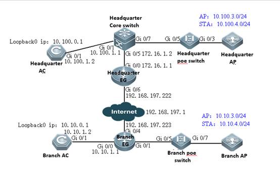
The following uses the preceding figure to describe solution deployment (deployment relating to authentication will be described specifically later).
Headquarters
As a network egress, EG is connected to networks through a static IP address. The gateway for LAN users resides on the headquarters core switch.
The of WAN bandwidth is 100 Mbps, the IP address of the WAN port is 192.168.197.222/24 (an IP address for tests and simulations, not the real carrier IP address), the IP address of the WAN gateway is 192.168.197.1, and the IP address of the LAN port is 172.16.1.1/24.
Gateways and Dynamic Host Configuration Protocol (DHCP) address pools of the AP and STA are deployed on the core switch. The AP resides on VLAN 3, and the STA resides on VLAN 4. The IP address of the AP gateway is 10.100.3.1, and the IP address of the STA gateway is 10.100.4.1.
The loopback IP address of the headquarters AC is 10.100.0.1. The SSID is wifi_test.
Branch
As a network egress, EG is connected to networks through a static IP address. The gateway for LAN users resides on the branch EG.
Gateways and DHCP address pools of the AP and STA are deployed on the branch EG. The AP resides on VLAN 3, and the STA resides on VLAN 4. The IP address of the AP gateway is 10.10.3.1, and the IP address of the STA gateway is 10.10.4.1.
The loopback IP address of the branch AC is 10.10.0.1. The SSID is wifi_test.
3.17.3.1 Deployment of Basic Networks for the Headquarters
After basic networks are deployed for the headquarters, the headquarters can access the Internet. Deployment of basic networks for the headquarters is not related to hierarchical ACs so that the networks can be deployed in traditional mode. However, deployment of hierarchical ACs is based on deployment of basic networks for the headquarters.
3.17.3.1.1 Configuration of Network Access Through the Headquarters EG
Network Topology
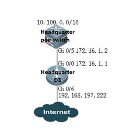
Networking Requirements
As a network egress, EG is connected to networks through a static IP address. The gateway for LAN users resides on the headquarters core switch.
The WAN bandwidth is 100 Mbps, the IP address of the WAN port is 192.168.197.222/24 (an IP address for tests and simulations, not the real carrier IP address), the IP address of the WAN gateway is 192.168.197.1, and the IP address of the LAN port is 172.16.1.1/24.
Configuration Tips
Confirm information on the WAN (for example, the IP address provided by the carrier) as well as the LAN and WAN ports (for example, the LAN port and WAN port of RG-EG2000K are marked with "LAN" and "WAN", respectively).
To connect a new EG to networks, start quick configuration. By default, the login IP address is 192.168.1.1, the user name and password are admin, and the LAN port ID is Gi0/0.
On the Advanced page, select Enable NAT and Enable Route, and configure the DNS.
Note: As the LAN is a private network, you need to enable NAT and routing to access the network. As a necessary parameter for system file updating and detection, the DNS must be configured.
Configuration Steps
Preparations
Set the PC IP address to 192.168.1.100/255.255.255.0. Insert the PC network cable into the EG port Gi0/0.
Enter the IP address of the EG LAN port (default IP address: 192.168.1.1; default user name/password: admin/admin) and log in to the router configuration page.

Quick Configuration
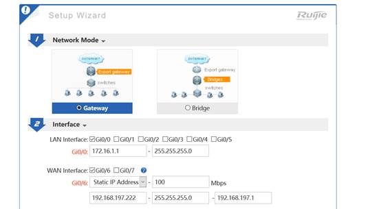
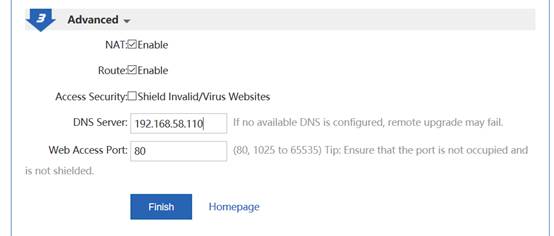
Note: As the IP address of Gi0/0 is changed from 192.168.1.1 to 172.16.1.1, you need to change the eWeb login IP address to 172.16.1.1.
Configure the back route to the LAN.
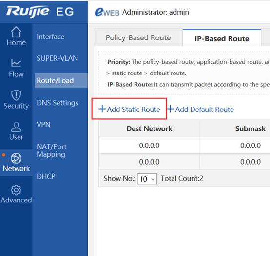
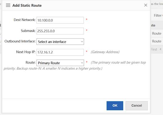
Configuration Verification
3.17.3.1.2 Configuration of the Headquarters Core Switch
Network Topology
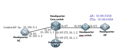
Networking Requirements
Gateways and DHCP address pools of the AP and STA are deployed on the core switch. The AP resides on VLAN 3, and the STA resides on VLAN 4. The IP address of the AP gateway is 10.100.3.1, and the IP address of the STA gateway is 10.100.4.1.
The loopback IP address of the headquarters AC is 10.100.0.1. The IP address of the headquarters core switch port Gi0/5 is 172.16.1.2, the IP address of Gi0/1 is 10.100.1.1, and the IP address of Gi0/3 is 10.100.2.1.
Configuration Steps
Preparations
Connect the PC to the core switch through a serial cable.
Configure DHCP address pools.
service dhcp
!
ip dhcp pool ap_vlan3 //Indicates the headquarters AP address pool.
option 138 ip 10.100.0.1
network 10.100.3.0 255.255.255.0 10.100.3.10 10.100.3.254
default-router 10.100.3.1
!
ip dhcp pool sta_vlan4 //Indicates the headquarters STA address pool.
network 10.100.4.0 255.255.255.0 10.100.4.10 10.100.4.254
dns-server 192.168.58.110
default-router 10.100.4.1
Configuring Ports, VLANs, and IP Addresses
vlan range 1,3,4 =======>VLAN 3 corresponds to the AP, and VLAN 4 corresponds to the STA.
!
interface GigabitEthernet 0/1 //Connects the headquarters AC.
no switchport
ip address 10.100.1.1 255.255.255.0
!
interface GigabitEthernet 0/5 //Connects the headquarters EG.
no switchport
ip address 172.16.1.2 255.255.255.0
!
interface GigabitEthernet 0/7 //Connects the PoE switch.
switchport mode trunk
switchport trunk native vlan 3
!
interface VLAN 3 //Indicates the headquarters AP gateway.
ip address 10.100.3.1 255.255.255.0
!
interface VLAN 4 //Indicates the headquarters STA gateway.
ip address 10.100.4.1 255.255.255.0
!
Configuring the Route
ip route 10.100.0.1 255.255.255.255 10.100.1.2 //Directs the route to the headquarters AC.
ip route 0.0.0.0 0.0.0.0 172.16.1.1 //Directs the route to the headquarters EG.
Configuration Verification
The large-scale network 192.168.197.1 can be pinged from the headquarters core switch.
3.17.3.1.3 Configuration of the Headquarters PoE Switch
Network Topology
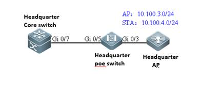
Networking Requirements
The AP resides on VLAN 3, and the STA resides on VLAN 4.
Configuration Steps
Preparations
Connect the PC to the PoE switch through a serial cable.
Configure ports, VLANs, and IP addresses.
vlan range 1,3,4 //VLAN 3 corresponds to the AP, and VLAN 4 corresponds to the STA.
!
interface GigabitEthernet 0/3 //Connects the headquarters AP.
switchport mode trunk
switchport trunk native vlan 3
switchport trunk allowed vlan only 3-4
poe enable
interface GigabitEthernet 0/5 //Connects the headquarters core switch.
switchport mode trunk
switchport trunk native vlan 3
switchport trunk allowed vlan only 3-4
poe enable
Show vlan:
ruijie# show vlan
VLAN Name Status Ports
---- -------------------------------- --------- -----------------------------------
3 VLAN03 STATIC Gi0/3, Gi0/5
4 VLAN04 STATIC Gi0/3, Gi0/5
3.17.3.1.4 Configuration of the Headquarters AC
Network Topology
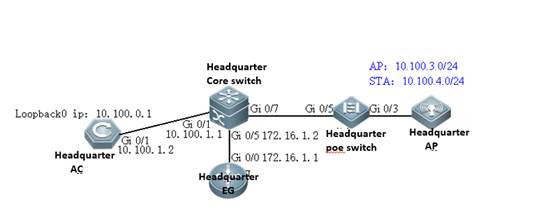
Networking Requirements
Set the IP address of Gi0/1 to 10.100.1.2. Configure the default route and direct the next hop to 10.100.1.1.
The loopback IP address of the branch AC is 10.100.0.1. Configuring the wireless network: The SSID is wifi_test, the ap-group name is Headquarters, the AP resides on VLAN 3, and the STA resides on VLAN 4.
Configuration Tips
By default, the Web service is enabled on the AC, the login IP address is 192.168.110.1, and the user name and password are admin. You can connect the PC to any port.
Configuration Steps
Preparations
Set the PC IP address to 192.168.110.100/255.255.255.0. Insert the PC network cable into any port of the AC.
Set the IP address of GI0/1 to 10.100.1.2.

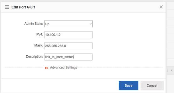
Configure the default route and direct the next hop to 10.100.1.1.
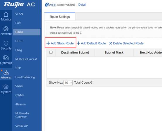
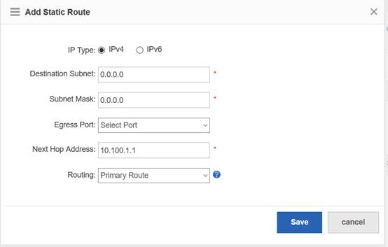
Configure the wireless network.
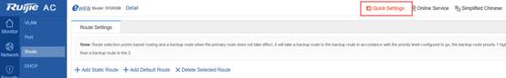
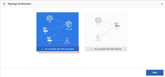
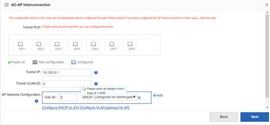
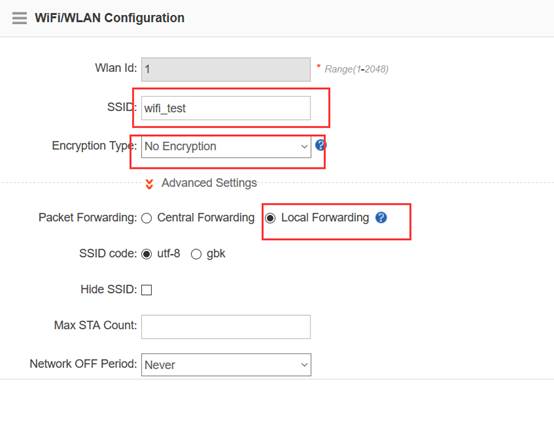
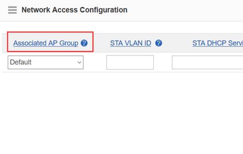
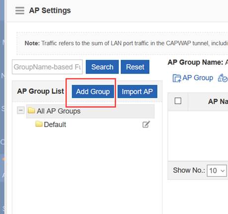
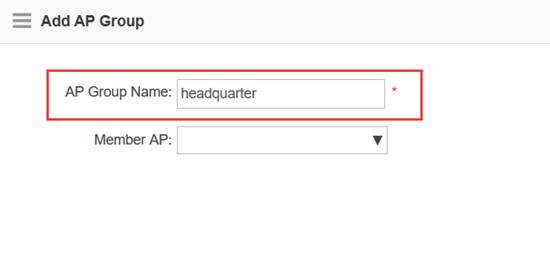
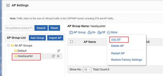
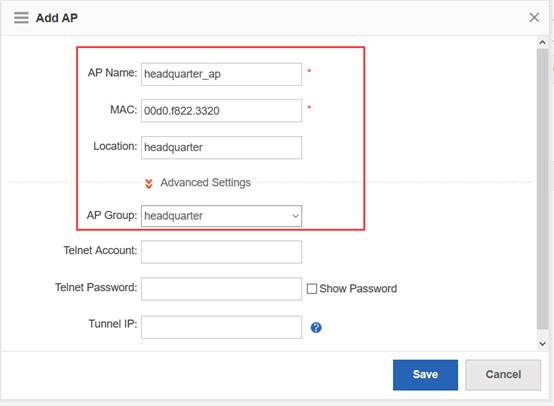
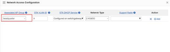
The preceding headquarters AC eWeb configuration corresponds to the following Command Line Interface (CLI).
wlan-config 1 wifi_test
ssid-code utf-8
tunnel local
!
ap-group headquarters
duplex full
description link to switch
ip address 10.100.1.2 255.255.255.0
!
interface Loopback 0
ip address 10.100.0.1 255.255.255.255
!
ip route 0.0.0.0 0.0.0.0 10.100.1.1
!
Ruijie#show ap-config running
Building configuration...
Current configuration: 89 bytes
!!!!!
ap-config headquarters ap
ap-mac 00d0.f822.3320
ap-group headquarters
location headquarters
!
end
Ruijie#
Configuration Verification
The mobile phone can be associated with the SSID wifi_test and can be connected to networks after being associated.
3.17.3.2 Deployment of Basic Networks for Branches
After basic networks are deployed for branches, the branches can access the Internet. Deployment of basic networks for the branches is not related to hierarchical ACs so that the networks can be deployed in traditional mode. However, deployment of hierarchical ACs is based on deployment of basic networks for branches.
3.17.3.2.1 Configuration of Network Access Through the Branch EG
Network Topology
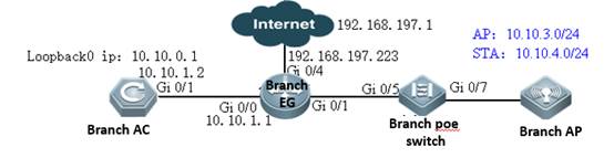
Networking Requirements
As a network egress, EG is connected to networks through a static IP address. The gateway for LAN users resides on the EG LAN port. You need to configure EG to access networks.
The WAN bandwidth is 10 Mbps, the IP address of the WAN port is 192.168.197.223/24 (an IP address for tests and simulations, not the real carrier IP address), the IP address of the WAN gateway is 192.168.197.1, and the IP address of the LAN port is 10.10.3.1/24.
Configuration Tips
Confirm information on the WAN (for example, the IP address provided by the carrier) as well as the LAN and WAN ports (for example, the LAN port and WAN port of RG-EG2000K are marked with "LAN" and "WAN", respectively).
To connect a new EG to networks, start quick configuration. By default, the login IP address is 192.168.1.1, the user name and password are admin, and the LAN port ID is Gi0/0.
On the Advanced page, select Enable NAT and Enable Route, and configure the DNS.
Note: As the LAN is a private network, you need to enableNATand routing to access the network. As a necessary parameter for system file updating and detection, the DNS must be configured.
Configuration Steps
Preparations
Set the PC IP address to 192.168.1.100/255.255.255.0. Insert the PC network cable into the EG port Gi0/0.
Enter the IP address of the EG LAN port (default IP address: 192.168.1.1; default user name/password: admin/admin) and log in to the router configuration page.
Quick Configuration
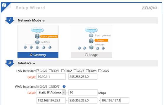
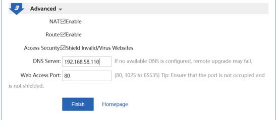
Note: As the IP address of Gi0/0 is changed from 192.168.1.1 to 10.10.3.1, you need to change the eWeb login IP address to 10.10.3.1.
Configuration Verification
3.17.3.2.2 Configuration of Branch EG Routes/DHCP
Network Topology

Networking Requirements
Gateways of the AP and STA are deployed on the branch EG. IP addresses of the gateways are 10.10.3.1 and 10.10.4.1, respectively. VLAN 3 corresponds to the AP, and VLAN 4 corresponds to the STA. Address pools of the AP and STA are deployed on the branch EG.
You need to configure the back route for the branch EG and set the IP address of the next hop (directed to 10.10.0.1) to 10.10.1.2.
Configuration Steps
Configure the IP addresses of AP and STA gateways.
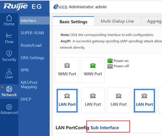
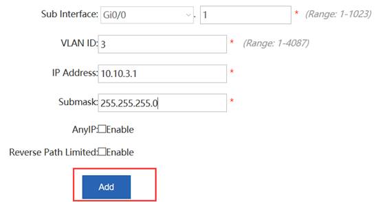
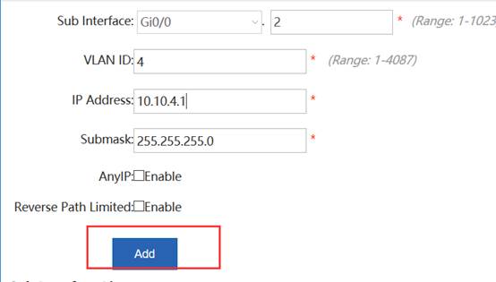
Configure AP and STA DHCP address pools.
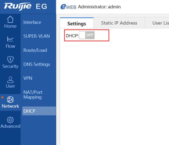
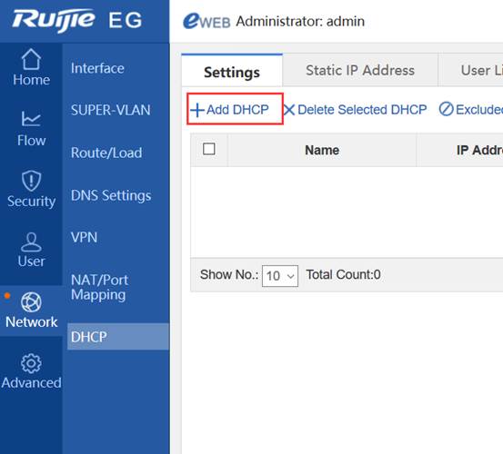
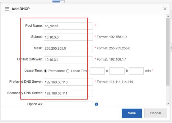
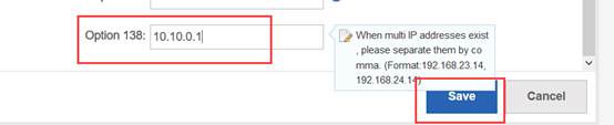
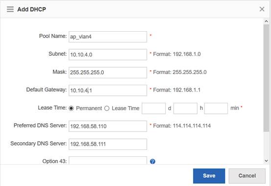
Configure the back route.
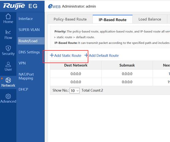
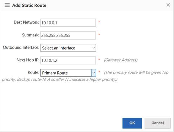
3.17.3.2.3 Configuration of Branch PoE Switches
Network Topology
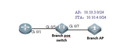
Networking Requirements
The AP resides on VLAN 3, and the STA resides on VLAN 4.
Configuration Steps
Preparations
Connect the PC to the PoE switch through a serial cable.
Configure ports and VLAN.
vlan range 1,3,4 =======>VLAN 3 corresponds to the AP, and VLAN 4 corresponds to the STA.
!
interface GigabitEthernet 0/7 =======>Connects the branch AP.
switchport mode trunk
switchport trunk native vlan 3
switchport trunk allowed vlan only 3-4
poe enable
interface GigabitEthernet 0/5 =======>Connects the branch EG.
switchport mode trunk
switchport trunk allowed vlan only 3-4
poe enable
Configuration Verification
l Show vlan:
ruijie# show vlan
VLAN Name Status Ports
---- -------------------------------- --------- -----------------------------------
3 VLAN03 STATIC Gi0/3, Gi0/5
4 VLAN04 STATIC Gi0/3, Gi0/5
3.17.3.2.4 Configuration of Branch ACs
Network Topology

Networking Requirements
Set the IP address of Gi0/1 to 10.10.1.2. Configure the default route and direct the next hop to 10.10.1.1.
The loopback IP address of the branch AC is 10.10.0.1. Configuring the wireless network: The SSID is wifi_test, the ap-group name is Branch, the AP resides on VLAN 3, and the STA resides on VLAN 4.
Configuration Tips
By default, the Web service is enabled on the AC, the login IP address is 192.168.110.1, and the user name and password are admin. You can connect the PC to any port.
Configuration Steps
Preparations
Set the PC IP address to 192.168.110.100/255.255.255.0. Insert the PC network cable into any port of the AC.
Set the IP address of Gi0/1 to 10.10.1.2.

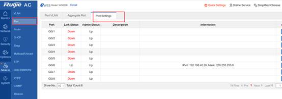
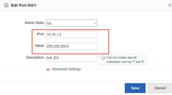
Configure the default route and direct the next hop to 10.10.1.1.
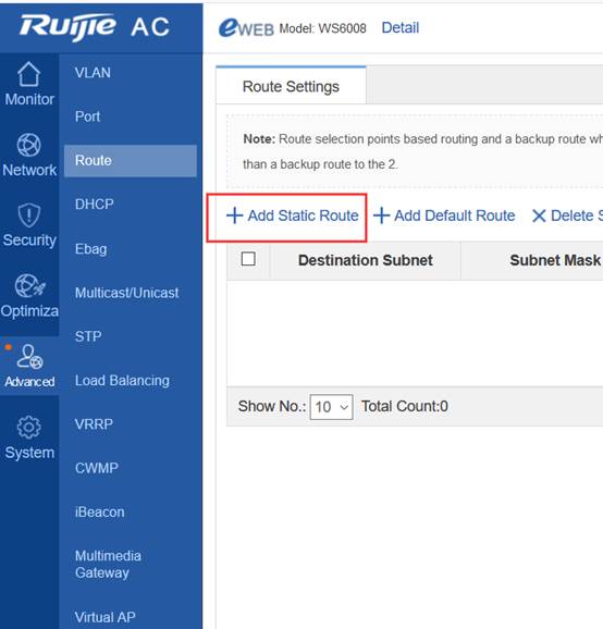
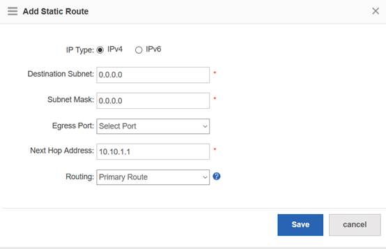
Configure the wireless network.
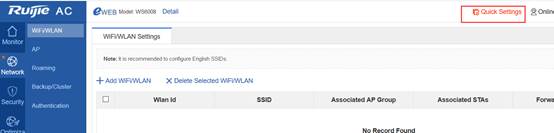
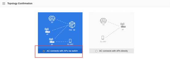
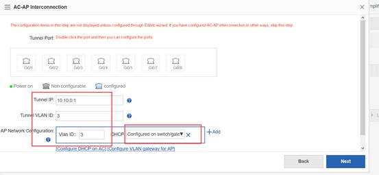
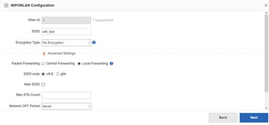
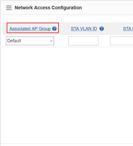
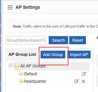
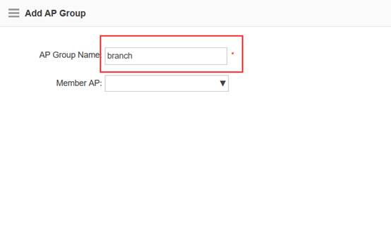
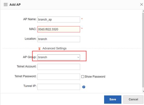
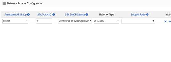
The preceding headquarters AC eWeb configuration corresponds to the following CLI.
wlan-config 2 wifi_test
ssid-code utf-8
tunnel local
!
ap-group branch
interface-mapping 2 4 ap-wlan-id 1
!
ac-controller
capwap ctrl-ip 10.10.0.1
!
vlan 3
!
vlan 4
!
interface GigabitEthernet 0/1
no switchport
speed 10
duplex full
description to_coreswitch
ip address 10.10.1.2 255.255.255.0
!
interface Loopback 0
ip address 10.10.0.1 255.255.255.255
!
ip route 0.0.0.0 0.0.0.0 10.10.1.1
!
Ruijie#show ap-config running
Building configuration...
Current configuration: 89 bytes
!!!!!
ap-config branch_ap
ap-mac 00d0.f822.3320
ap-group branch
location branch
!
end
Ruijie#
Configuration Verification
3.17.3.3 Deployment of Paths Between Branches and the Headquarters
3.17.3.3.1 Interworking Between the Headquarters and Branches Through Dedicated Lines
3.17.3.3.2 Establishing VPN Paths Between the Headquarters and Branches
Network Topology
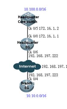
Networking Requirements
When an IPSec VPN is established between branch and headquarters, the 10.10.0.0/16 segment of the branch and the 10.100.0.0/16 segment of the headquarters can access each other.
Configuration Steps
Configure the headquarters EG.
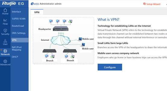

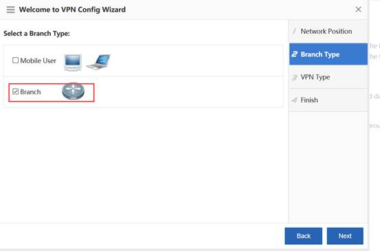
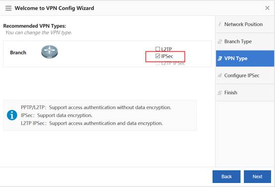
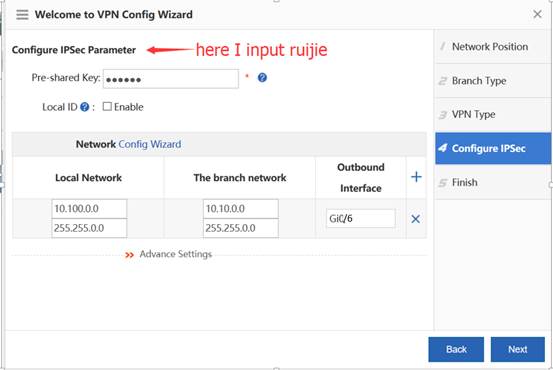
Configure the branch EG.

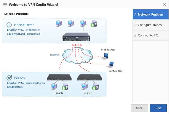
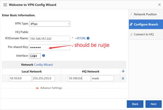
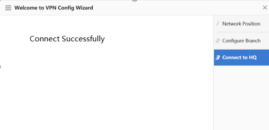
Configuration Verification
Log in to the Web console of the branch AC and ping the loopback IP address of the headquarters AC from the branch AC. Confirm that the loopback IP address can be pinged.
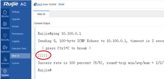
3.17.3.3.3 Mapping Addresses of LANs to WANs for Interworking
3.17.3.4 Deployment of Hierarchical Relationship Between Centerand Branch ACs
3.17.3.4.1 Establishing a Hierarchical Relationship
Networking Requirements
A hierarchical relationship needs to be established between center and branch ACs.
Configuration Steps
Hierarchical ACs back up data of center and branch devices by using the hot backup technology to enable failover. Therefore, wireless networks need to be deployed for the headquartersas if during hot backup deployment so that when branch ACs fail the center AC can take over branches with the same configuration. Therefore, the following operations should be performed on the center AC.
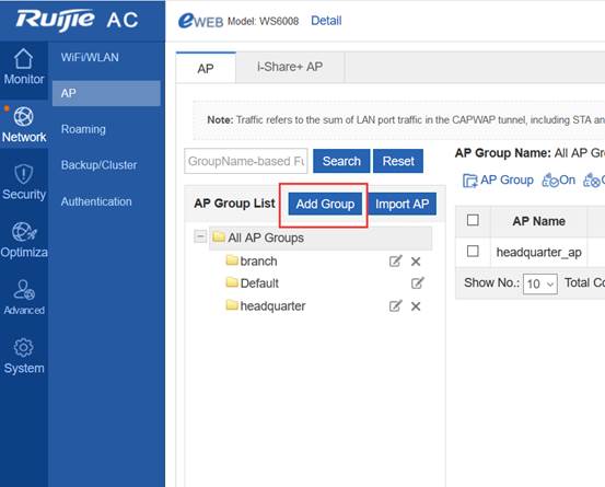
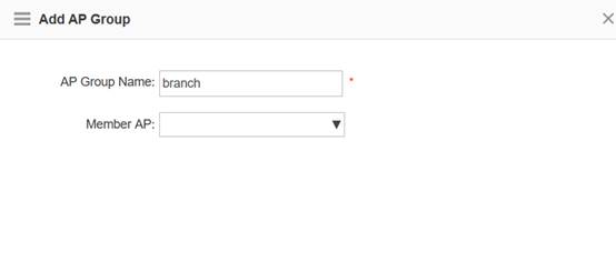
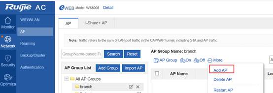
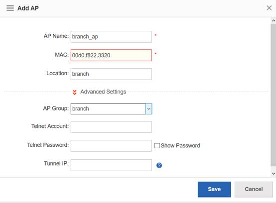
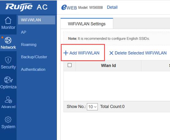
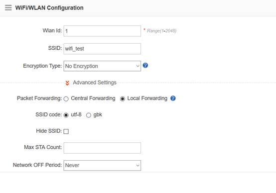
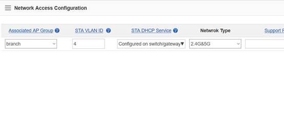
The preceding eWeb configuration corresponds to the following CLI.
wlan-config 2 wifi_test
ssid-code utf-8
tunnel local
!
ap-group branch
interface-mapping 2 4 ap-wlan-id 1
!
vlan 4
!
Ruijie#show ap-config running
Building configuration...
Current configuration: 89 bytes
!!!!!
ap-config branch_ap
ap-mac 00d0.f822.3320
ap-group branch
location branch
!
end
Ruijie#
Configure branch ACs to establish a hierarchical relationship between center and branch ACs.
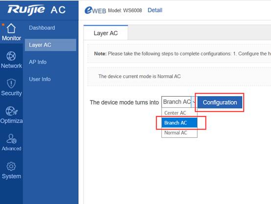
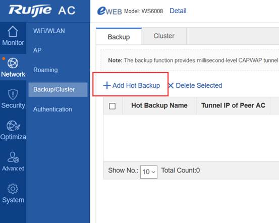
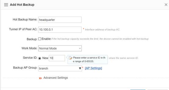
The preceding eWeb configuration corresponds to the following CLI.
wlan hot-backup branch //Indicates that the device is a branch AC, which reflects the major difference between hierarchical ACs and common wireless hot backup.
!
wlan hot-backup 10.100.0.1 //Indicates the CAPWAP tunnel IP address of the headquarters AC, which must be pinged to establish a hierarchical relationship.
description headquarters
!
context 10
priority level 7 //Indicates that the priority level is 7, which supports switchback during failback.
ap-group branch
!
wlan hot-backup enable
Configure branch ACs to establish a hierarchical relationship between center and branch ACs.
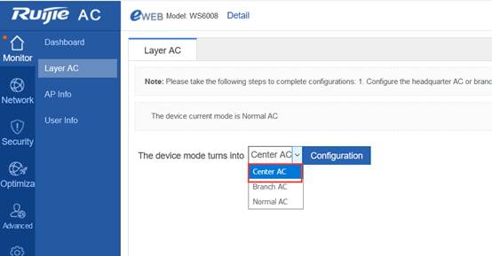
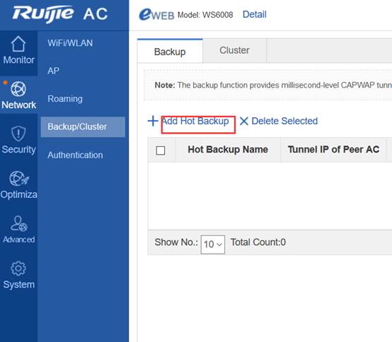
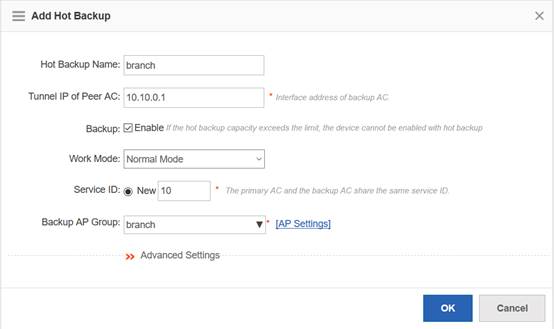
The preceding eWeb configuration corresponds to the following CLI.
wlan hot-backup center //Indicates that the device is a center AC, which reflects the major difference between hierarchical ACs and common wireless hot backup.
!
wlan hot-backup 10.10.0.1 //Indicates the CAPWAP tunnel IP address of the branch AC, which must be pinged to establish a hierarchical relationship.
description branch //Describes branch ACs to help you tell them apart.
!
context 10
ap-group branch
!
wlan hot-backup enable
Check branch ACs on the center AC. The branch ACs are "Online".
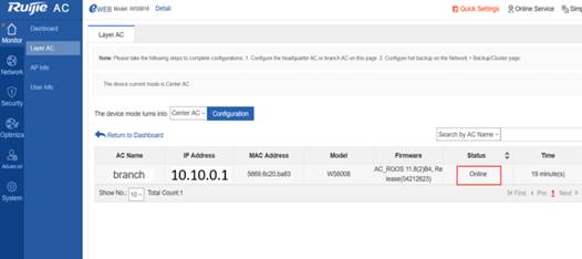
Check APs on the center AC. Both branch and center APs are "Online".

After the mobile phone is associated with the SSID wifi_test, whether in the headquarters or branches, it can be connected to networks.
3.17.3.4.2 Monitoring Hierarchical Networks in Unified Mode
On the center AC, you can check which branch ACs are online, branch AC name, IP address, model, status, software version, CPU utilization, memory utilization, number of APs, and number of users.
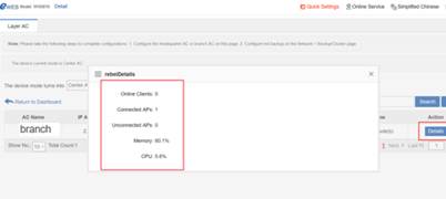
On the center AC, you can check which APs are online and to which branch each AP belongs.
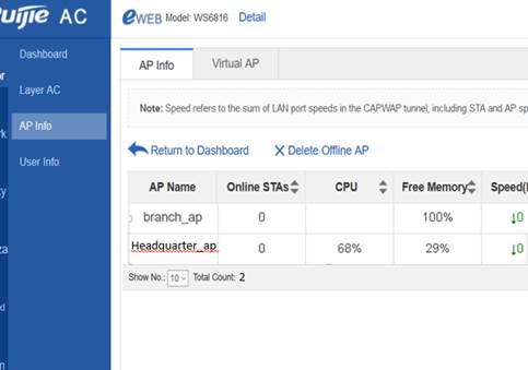
On the center AC, you can check which terminals are online and to which branch each terminal belongs.
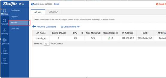
3.17.3.4.3 UpgradingHierarchical Networks in Unified Mode
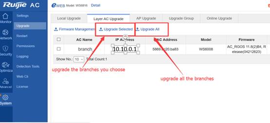
Note: Currently, you can upload version files to the flash memory or use a USB flash disk to upgrade devices. For the ACs without USB ports (WS6812 and WS6816 support USB flash disks, while M8600E-WS-ED and M18000-WS-ED do not support USB flash disks), if multiple models of ACs and APs exist in a branch, the flash memory space may be inadequate for .bin files of all ACs and APs; therefore, devices need to be upgraded in batches.
If the flash memory space is inadequate, you can delete some idle .bin files on eWeb to make room for new .bin files.
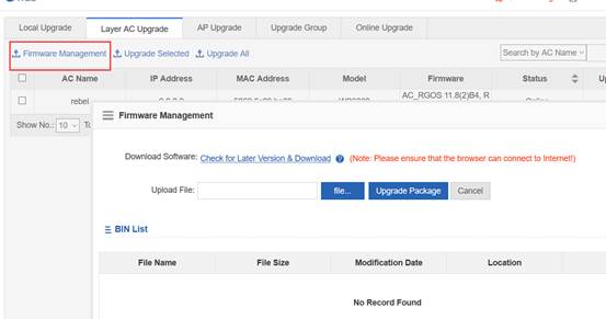
Alternatively, you can enter the treecommand on the CLI, find all .bin files, and delete idle ones to make room for new .bin files.
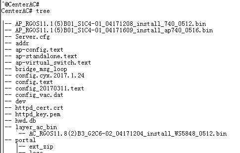
3.17.3.5 Deployment Authentication
3.17.3.5.1 Centralized Authentication in the Headquarters
Network Topology
Networking Requirements
The authentication server is connected to the headquarters core switch, and its IP address is 10.100.2.2.
The following uses dot1x authentication as an example. The user name and password are test.
Configuration Steps
Select dot1x authentication for ACs in branches and headquarters, as shown in the following figure.
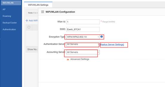
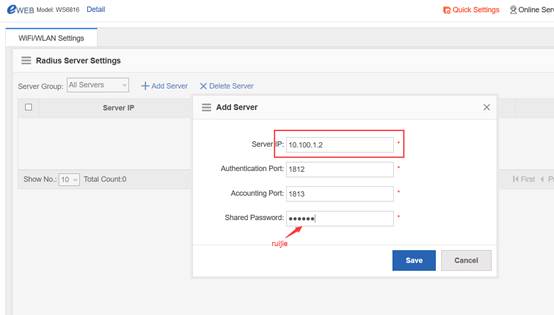
On the RADIUS server, add devices (center and branch ACs) and register an account (in the following figure, the center AC is added; branch ACs should be added following the same procedures). Then correlate the mobile phone to wifi_test, and enter the user name and password.
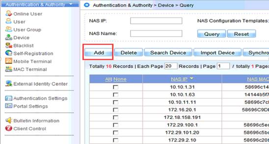
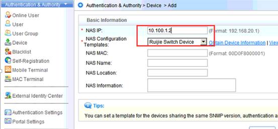
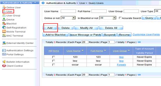
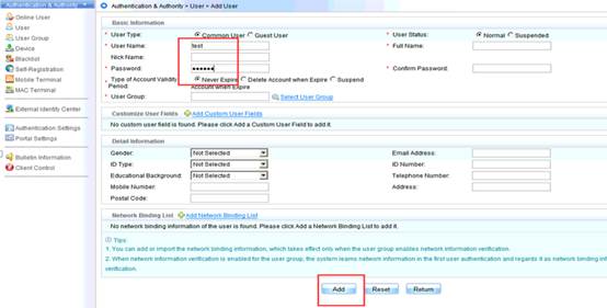
Configuration Verification
3.17.3.5.2 Distributed Authentication in the Headquarters
There is no difference between deployment for distributed authentication and deployment for centralized authentication except the IP addresses of local authentication servers are used as those of the authentication servers on ACs. Deployment for distributed authentication in hierarchical AC mode is detailed in the ESS/IPC Configuration Guide.
3.18 Smart AP
3.18.1 Overview
3.18.1.1 Background
Access points (APs) are used for mobile offices. For safety, ports cannot be mapped to public networks on access controllers (ACs). Layer 2 Tunneling Protocol (L2TP) is used to establish tunnels between APs and the headquarters egress gateway, based on which CAPWAP tunnels are established. ACs assign network access configurations to forward in centralized mode, which significantly simplizes network access configuration for AP mobile offices. Figures 1-2(1) and 1-2(2) show common scenarios.
Figure 1-2(1) AP Point-to-Point Protocol over Ethernet (PPPoE) dial-up scenario
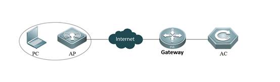
In the preceding scenario, the number is dialed through PPPoE on the AP, and then the AP is connected to large-scale networks. An L2TP tunnel is established between the AP and egress gateway. A CAPWAP tunnel is established between the AP and AC through the L2TP tunnel.
Figure 1-2(2) AP Dynamic Host Configuration Protocol (DHCP) scenario
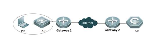
3.2 Components and Version
| Area |
Product Name |
Function |
Version |
Remarks |
| Branch |
Wireless AP |
Wireless forwarding path |
Later than V11.8PJ4 |
Supported by specific versions and models |
| Power over Ethernet (PoE) switch |
PoE |
Unlimited |
N/A |
|
| Easy Gateway (EG) |
Gateway, VPN, traffic control, and network address translation (NAT) |
Unlimited |
N/A |
|
| Headquarters |
Wireless AP |
Wireless forwarding path |
Later than V11.x B8 |
N/A |
| PoE switch |
PoE |
Unlimited |
N/A |
|
| Wireless AC |
Box wireless AP controller or board-style (N18K) wireless AP controller |
Unlimited |
N/A |
|
| Gateway switch |
Gateway |
Unlimited |
N/A |
|
| EG |
Gateway, VPN, traffic control, and NAT |
Unlimited |
N/A |
3.18.2 Preparation for Deployment
3.18.2.1 Device Selection
3.18.3 Deployment Guide
APs can be connected to networks through DHCP, PPPoE, or static IP addresses, as shown in Figures 3-1 and 3-2.
Figure 3-1 Connecting APs to networks through DHCP

Figure 3-2 Connecting APs to networks through PPPoE
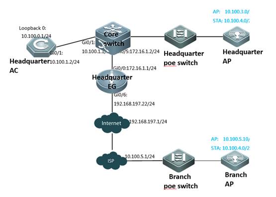
Figure 3-3 Connecting APs through static IP addresses
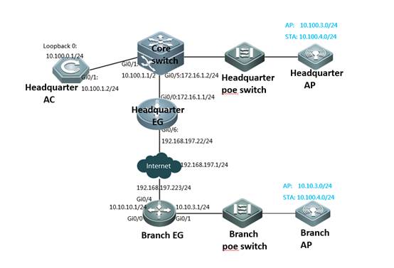
The following uses the preceding figures to describe solution deployment.
Headquarters
As a network egress, EG is connected to networks through a static IP address. The gateway for Local Area Network (LAN) users resides on the headquarters core switch.
The Wide Area Network (WAN) bandwidth is 100 Mbps, the IP address of the WAN port is 192.168.197.222/24 (an IP address for tests and simulations, not the real carrier IP address), the IP address of the WAN gateway is 192.168.197.1, and the IP address of the LAN port is 172.16.1.1/24.
Gateways and DHCP address pools of the AP and STA are deployed on the core switch. The AP resides on VLAN 3, and the STA resides on VLAN 4. The IP address of the AP gateway is 10.100.3.1, and the IP address of the STA gateway is 10.100.4.1.
The loopback IP address of the headquarters AC is 10.100.0.1. The Service Set Identifier (SSID) is wifi_test.
Branch (DHCP)
As a network egress, EG is connected to networks through a static IP address. The gateway for LAN users resides on the branch EG.
The WAN bandwidth is 10 Mbps, the IP address of the WAN port is 192.168.197.223/24 (an IP address for tests and simulations, not the real carrier IP address), the IP address of the WAN gateway is 192.168.197.1, and the LAN IP address is 10.10.3.0/24.
The gateway and DHCP address pool of the AP are deployed on the branch EG. The AP resides on VLAN 3. The IP address of the AP gateway is 10.10.3.1.
The gateway and address pool of the STA are deployed on the headquarters core switch. The IP address of the STA gateway is 10.100.4.1.
Branch (PPPoE):
A static IP address is configured for the branch AP. The IP address of the AP gateway is 10.10.5.1. The IP address of the AP is 10.100.5.10 (an IP address for tests and simulations, not the real carrier IP address).
The gateway and address pool of the STA are deployed on the headquarters core switch. The IP address of the STA gateway is 10.100.4.1.
Static IP address
The number is dialed through PPPoE on the AP. The IP address of the AP gateway is 10.10.3.1. The IP address of the AP is 10.100.3.10 (an IP address for tests and simulations, not the real carrier IP address).
3.18.3.1 Deployment of Basic Networks for the Headquarters
3.18.3.1.1 Configuration of Network Access Through the Headquarters EG
Network Topology
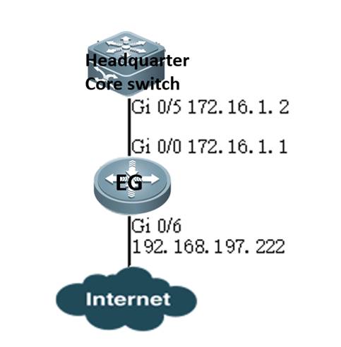
Networking Requirements
As a network egress, EG is connected to networks through a static IP address. The gateway for LAN users resides on the headquarters core switch.
The WAN bandwidth is 100 Mbps, the IP address of the WAN port is 192.168.197.222/24 (an IP address for tests and simulations, not the real carrier IP address), the IP address of the WAN gateway is 192.168.197.1, and the IP address of the LAN port is 172.16.1.1/24.
Configuration Tips
Confirm information on the WAN (for example, the IP address provided by the carrier) as well as the LAN and WAN ports (for example, the LAN port and WAN port of RG-EG2000K are marked with "LAN" and "WAN", respectively).
To connect a new EG to networks, start quick configuration. By default, the login IP address is 192.168.1.1, the user name and password are admin, and the LAN port ID is Gi0/0.
On the Advanced page, select Enable NAT and Enable Route, and configure the DNS.
Configure the VPDN server.
Note: As the LAN is a private network, you need to enableNATand routing to access the network. As a necessary parameter for system file updating and detection, the DNS must be configured.
Configuration Steps
Enter the IP address of the EG LAN port (default IP address: 192.168.1.1; default user name/password: admin/admin) and log in to the router configuration page.
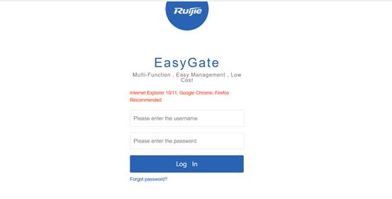
Quick Configuration
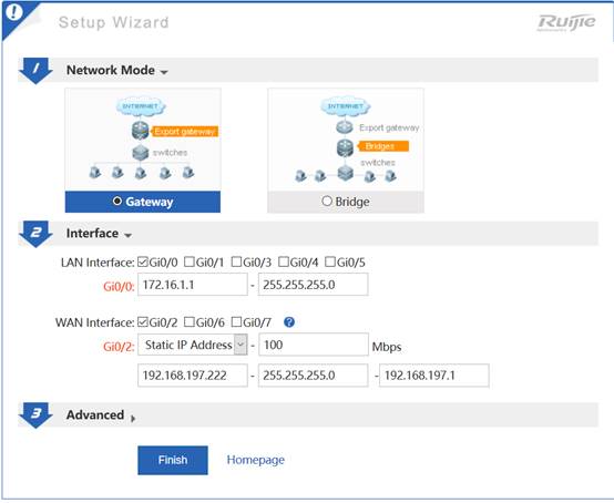
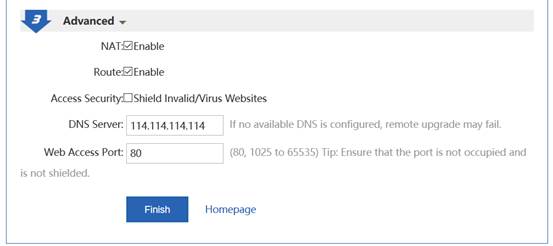
Note: As the IP address of Gi0/0 is changed from 192.168.1.1 to 172.16.1.1, you need to change the eWeb login IP address to 172.16.1.1.
Configure the back route to the LAN.
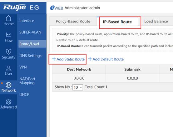
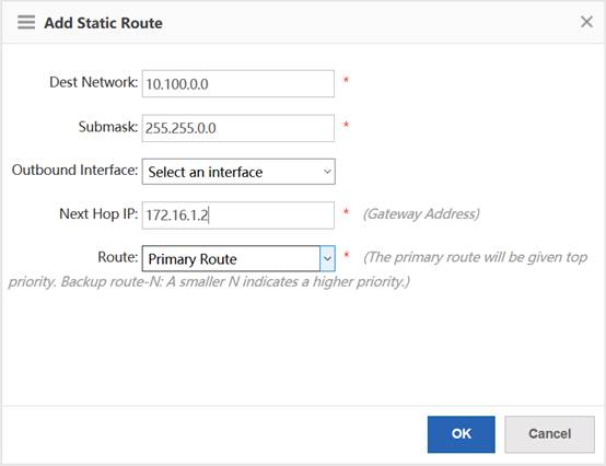
Configure the VPDN server.
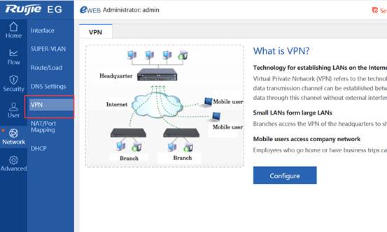
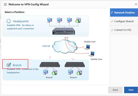
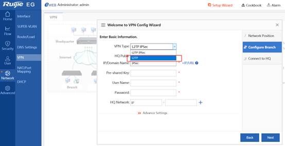
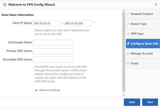
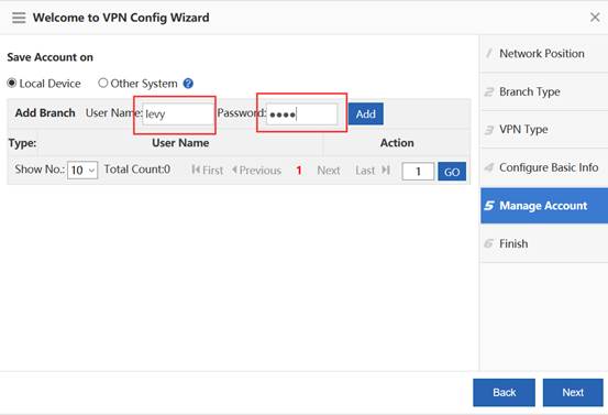
Configuration Verification
3.18.3.1.2 Configuration of the Headquarters Core Switch
Network Topology
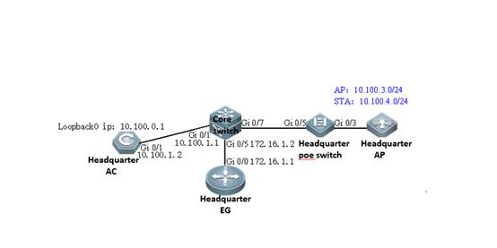
Networking Requirements
Gateways and DHCP address pools of the AP and STA are deployed on the core switch. The AP resides on VLAN 3, and the STA resides on VLAN 4. The IP address of the AP gateway is 10.100.3.1, and the IP address of the STA gateway is 10.100.4.1.
The loopback IP address of the headquarters AC is 10.100.0.1. The IP address of the headquarters core switch port Gi0/5 is 172.16.1.2, the IP address of Gi0/1 is 10.100.1.1, and the IP address of Gi0/3 is 10.100.2.1.
Configuration Steps:
Configure the DHCP address pool.
service dhcp
!
ip dhcp pool ap_vlan3 //Indicates the headquarters AP address pool.
option 138 ip 10.100.0.1
network 10.100.3.0 255.255.255.0 10.100.3.10 10.100.3.254
default-router 10.100.3.1
!
ip dhcp pool sta_vlan4 //Indicates the headquarters STA address pool.
network 10.100.4.0 255.255.255.0 10.100.4.10 10.100.4.254
dns-server 192.168.58.110
default-router 10.100.4.1
Configure ports, VLANs, and IP addresses.
vlan range 1,3,4 // VLAN 3 corresponds to the AP, and VLAN 4 corresponds to the STA.
!
interface GigabitEthernet 0/1 //Connects the headquarters AC.
no switchport
ip address 10.100.1.1 255.255.255.0
!
interface GigabitEthernet 0/5 //Connects the headquarters EG.
no switchport
ip address 172.16.1.2 255.255.255.0
!
interface GigabitEthernet 0/7 =======> Connects the PoE switch.
switchport mode trunk
switchport trunk native vlan 3
!
interface VLAN 3 ======> Indicates the headquarters AP gateway.
ip address 10.100.3.1 255.255.255.0
!
interface VLAN 4 ======>Indicates the headquarters STA gateway.
ip address 10.100.4.1 255.255.255.0
!
Configure the route.
ip route 10.100.0.1 255.255.255.255 10.100.1.2 ====>Directs the route to the headquarters AC.
ip route 0.0.0.0 0.0.0.0 172.16.1.1 ====>Directs the route to the headquarters EG.
Configuration Verification
The large-scale network 192.168.197.1 can be pinged from the headquarters core switch.
3.18.3.1.3 Configuration of the Headquarters PoE Switch
Network Topology

Networking Requirements
The AP resides on VLAN 3, and the STA resides on VLAN 4.
Configuration Steps
Configure ports, VLANs, and IP addresses.
vlan range 1,3,4 =======>VLAN 3 corresponds to the AP, and VLAN 4 corresponds to the STA.
!
interface GigabitEthernet 0/3 =======> Connects the headquarters AP.
switchport mode trunk
switchport trunk native vlan 3
switchport trunk allowed vlan only 3-4
poe enable
interface GigabitEthernet 0/5 =======>Connects the headquarters core switch.
switchport mode trunk
switchport trunk native vlan 3
switchport trunk allowed vlan only 3-4
poe enable
Configuration Verification
Show vlan:
ruijie# show vlan
VLAN Name Status Ports
---- -------------------------------- --------- -----------------------------------
3 VLAN03 STATIC Gi0/3, Gi0/5
4 VLAN04 STATIC Gi0/3, Gi0/5
3.18.3.1.4 Configuration of the Headquarters AC
Network Topology
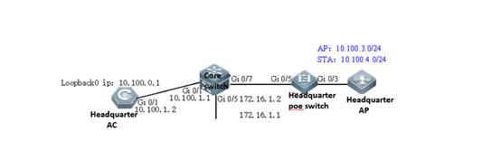
Networking Requirements
Set the IP address of Gi0/1 to 10.100.1.2. Configure the default route and direct the next hop to 10.100.1.1.
The loopback IP address of the branch AC is 10.100.0.1. Configuring the wireless network: The SSID is wifi_test, the ap-group name is Headquarters, the AP resides on VLAN 3, and the STA resides on VLAN 4.
Configuration Tips
By default, the Web service is enabled on the AC, the login IP address is 192.168.110.1, and the user name and password are admin. You can connect the PC to any port.
Configuration Steps
Set the IP address of Gi0/1 to 10.100.1.2.
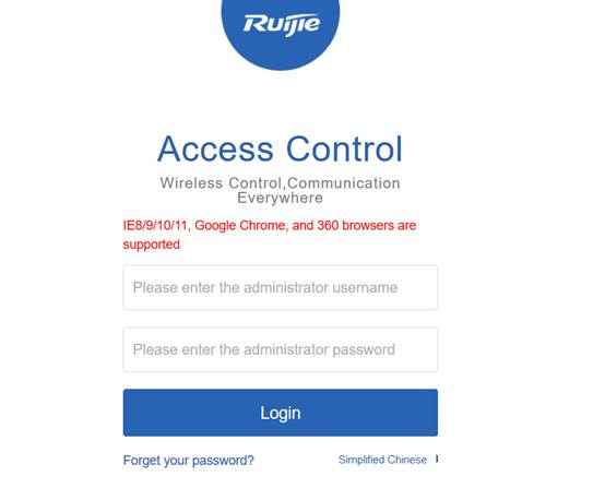
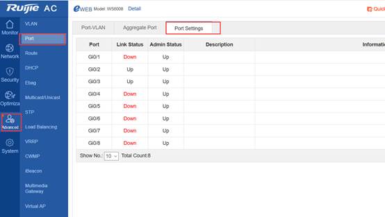
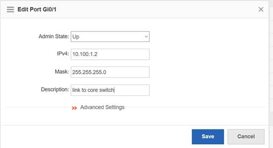
Configure the default route and direct the next hop to 10.100.1.1.
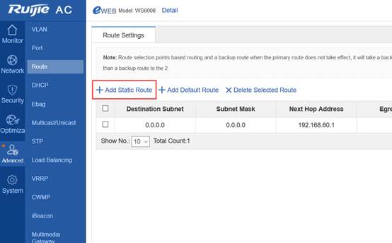
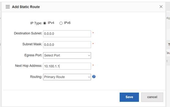
Configure the wireless network.
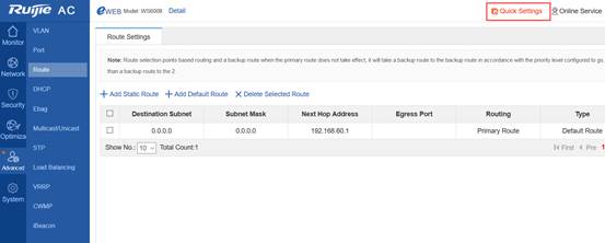
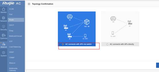
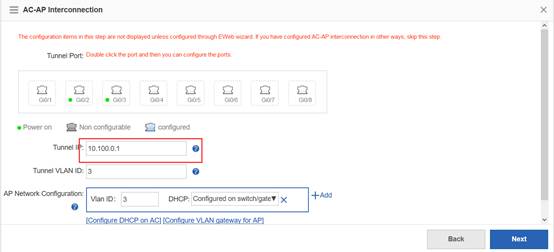
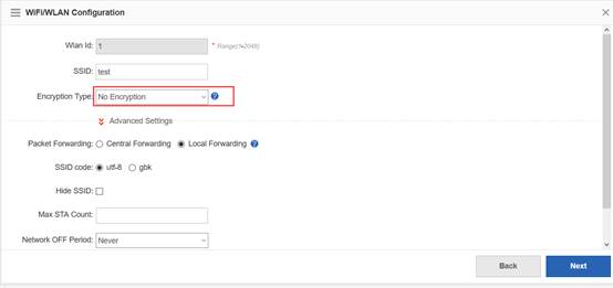
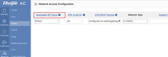
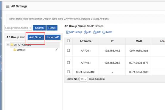
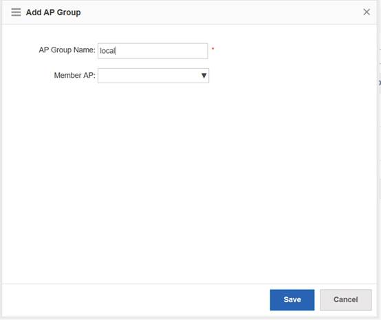
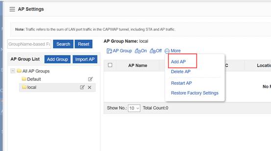
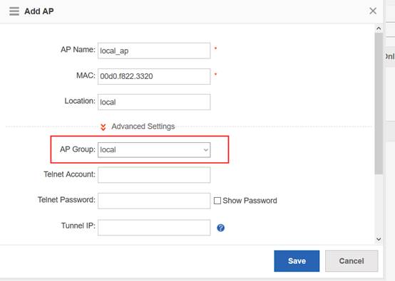
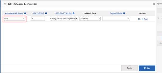
Configuration Verification
3.18.3.2 Deployment of Basic Networks in DHCP Mode for Branches
3.18.3.2.1 Configuration of Network Access Through the Branch EG
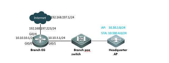
Networking Requirements
As a network egress, EG is connected to networks through a static IP address. The gateway for LAN users resides on the EG LAN port. You need to configure EG to access networks.
The WAN bandwidth is 10 Mbps, the IP address of the WAN port is 192.168.197.223/24 (an IP address for tests and simulations, not the real carrier IP address), the IP address of the WAN gateway is 192.168.197.1, and the IP address of the LAN port is 10.10.3.1/24.
Configuration Tips
Confirm information on the WAN (for example, the IP address provided by the carrier) as well as the LAN and WAN ports (for example, the LAN port and WAN port of RG-EG2000K are marked with "LAN" and "WAN", respectively).
To connect a new EG to networks, start quick configuration. By default, the login IP address is 192.168.1.1, the user name and password are admin, and the LAN port ID is Gi0/0.
On the Advanced page, select Enable NAT and Enable Route, and configure the DNS.
Note: As the LAN is a private network, you need to enable NAT and routing to access the network. As a necessary parameter for system file updating and detection, the DNS must be configured.
Configuration Steps
Enter the IP address of the EG LAN port (default IP address: 192.168.1.1; default user name/password: admin/admin) and log in to the router configuration page.
Quick Configuration
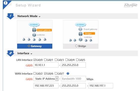
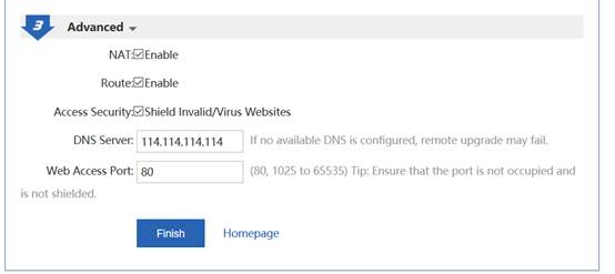
Note: As the IP address of Gi0/0 is changed from 192.168.1.1 to 10.10.3.1, you need to change the eWeb login IP address to 10.10.3.1.
Configuration Verification
3.18.3.2.2 Configuration of Branch EG Routes/DHCP
Network Topology
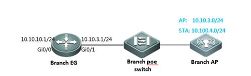
Networking Requirements
The AP gateway is deployed on the branch EG. The gateway IP address is 10.10.3.1. The AP resides on VLAN 3. The AP address pool is deployed on the branch EG.
Configuration Steps
Configure the IP address of the LAN port.
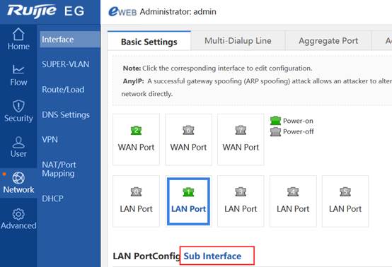
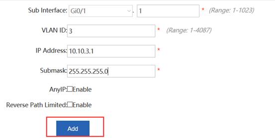
Configure the AP address pool.
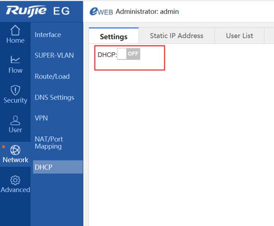
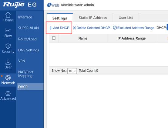
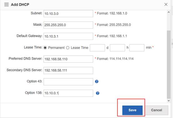
3.18.3.2.3 Configuration of Branch PoE Switches
Network Topology
Networking Requirements
AP resides on VLAN 3.
Configuration Steps
Configure ports and VLANs.
vlan range 1,3,4 =======>VLAN 3 corresponds to the AP.
!
interface GigabitEthernet 0/7 =======>Connects the branch AP.
switchport mode trunk
switchport trunk native vlan 3
switchport trunk allowed vlan only 3
poe enable
interface GigabitEthernet 0/5 =======>Connects the branch EG.
switchport mode trunk
switchport trunk allowed vlan only 3
poe enable
Configuration Verification
show vlan:
ruijie# show vlan
VLAN Name Status Ports
---- -------------------------------- --------- -----------------------------------
3 VLAN03 STATIC Gi0/5, Gi0/7
3.18.3.2.4 Configuration of Branch APs
Configuration Steps
Connect the PC to the AP, set a PC IP address to that of the 192.168.110.0/24 network segment, for example, 192.168.110.10.
Log in to the AP Web page and enter the AP IP address (192.168.110.1 by default), as shown in the following figure.
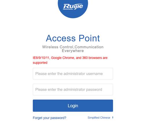
Enter the user name admin and password admin, and click Login, as shown in the following figure.

Tunnel Configuration
Configure the SSID and active AP IP address, turn the Tunnel switch to ON position, enter the headquarters IP address, click Yes for Access AC Through, and enter the user name or password (if no user name or password has been set, use the serial number as the user name and password), as shown in the following figure.
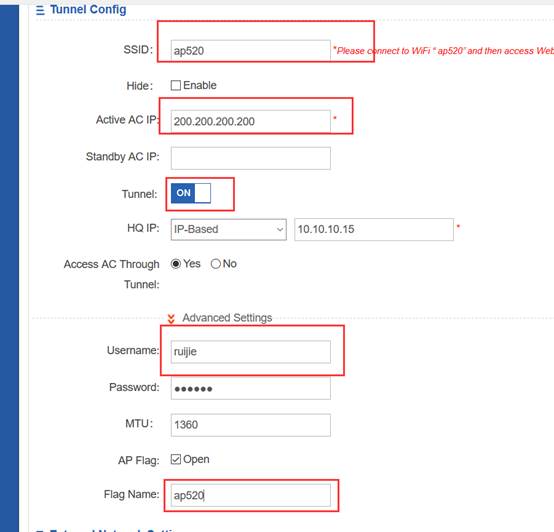
WAN Settings
Select DHCP (Dynamic IP) as an Internet connection type, as shown in the following figure.

Click Save.
Connect the LAN cable to the DHCP server.
Configuration Verification
3.18.3.3 Deployment of Basic Networks in PPPoE Mode for Branches
3.18.3.3.1 Configuration of Branch APs
Configuration Steps
Connect the PC to the AP and set the Network Interface Card (NIC) IP address to 192.168.110.10.
Log in to the AP Web page and enter 192.168.110.1, as shown in the following figure.
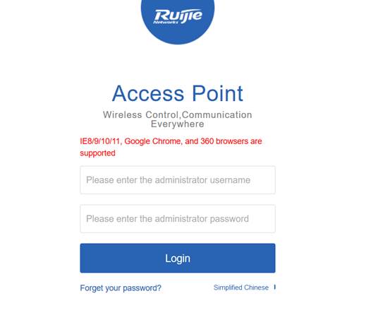
Enter the user name admin and password admin, and click Login, as shown in the following figure.

Tunnel Configuration
Configure the SSID and active AP IP address, turn the Tunnel switch to ON position, enter the headquarters IP address, click Yes for Access AC Through, and enter the user name or password (if no user name or password has been set, use the serial number as the user name and password), as shown in the following figure.
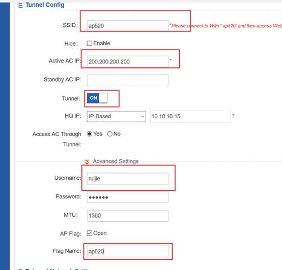
WAN Settings
Select PPPoE (ADSL Line) as an Internet connection type, as shown in the following figure.
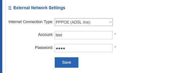
Enter the account and password, and click Save.
Connect the egress cable to the PPPoE server.
Configuration Verification
3.18.3.4 Deployment of Basic Networks in Static Mode for Branches
3.18.3.4.1 Configuration of Branch APs
Configuration Steps
Connect the PC to the AP and set the NIC IP address to 192.168.110.10.
Log in to the AP Web page and enter 192.168.110.1, as shown in the following figure.

Enter the user name admin and password admin, and click Login, as shown in the following figure.

Tunnel Configuration
Configure the SSID and active AP IP address, turn the Tunnel switch to ON position, enter the headquarters IP address, click Yes for Access AC Through, and enter the user name or password (if no user name or password has been set, use the serial number as the user name and password), as shown in the following figure.
Note: When networks are deployed through static IP addresses, select IP-Based rather than DNS-Based for the headquarters IP address.
WAN Settings
Select Static IP (Dedicated IP) as an Internet connection type, as shown in the following figure.
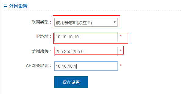
Enter the IP address, subnet mask, and AP gateway address. Click Save.
Connect the egress cable to WANs.
Configuration Verification
Solutions
4.1 Bring Your Own Device (BYOD)
4.1.1 Understanding BYOD

“Bring Your Own Device means the policy of permitting individuals to bring personally owned mobile devices to their work place, and use to access privileged company information and applications.”-source from Wikipedia
Not like traditional WLAN authenitcation, BYOD does not require wireless users install specific authentication clients, in this case BYOD has a good compatibility for more and more mobile and laptop devices.
Ruijie offers a comprehensive solution to address an extensive array of BYOD requirements and challenges such as wireless coverage, access control and unified management. The architecture design of the solution is as follows:
4. Wireless coverage:
X-Sense and i-Share wireless coverage solution
4.11n and 802.11ac Gigabit WiFi
Simultaneously manage at least 200 wireless access points (APs)
4. Access control:
Seamless staff wireless authentication
Role-based network access control
Self-service Email/SMS guest account management
Unique QR code guest authentication
4. Unified management:
Visualization management of wireless device and remote fault location
Unified management of wired, wireless and Virtual Private Network (VPN) users
Integration with Identity Management System (e.g. LDAP, Microsoft AD)
Proactive alert management via Email / SMS
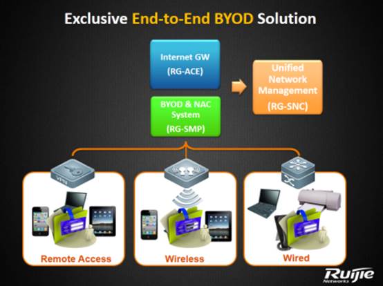
4.1.2 Configuring BYOD
BYOD Components
In BYOD Scenario, besides basic network infrastructures, following components are required: SMP Server, Wireless Controller and Access Point.
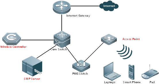
BYOD Solution for Staffs No.1: 802.1x Seamless Authentication
Step 1: connects one wireless equipment to SSID “802.1x”, fill in username and password. In several seconds, equipment passes authentication, then you can start surfing Internet.
Step 2: Bring the equipment out of wireless coverage, then wireless network interrupts.
Step 3: Bring the authenticated equipment back into the wireless coverage, then this equipment will pass the authentication automatically at the back end, and no more manual intervention is required before you start surfing Internet.
BYOD Solution for Staffs No.2: Web Seamless Authentication
Step 1: connects one wireless equipment to SSID “WebAuth”, authentication portal pops up automatically soon. Fill in username and password. In several seconds, equipment passes authentication, then you can start surfing Internet.
Step 2: Bring the equipment out of wireless coverage, then wireless network interrupts.
Step 3: Bring the authenticated equipment back into the wireless coverage, then this equipment will pass the authentication automatically at the back end, and no more manual intervention is required before you start surfing Internet.
BYOD Solution for Visitors No.3: QRCode Authentication
Step 1: Staff passes“802.1x”or “WebAuth”authentication first
Step 2: Visitors connects to SSID “Visitors”, authentication portal pops up automatically soon, displaying a QRCode Diagram.
Step 3: Staff scans the QR Code, and set the validation period for this temple account (1 day at most).
Step 4: Visitors passes authentication and start surfing.
BYOD Solution for Visitors No.4: SMS Registration Authentication
Step 1: Visitors connects to SSID “Visitors-AUTO”, authentication portal pops up automatically soon.
Step 2: Choose Tab “Visitors Authentication” and fill in the phone number, then click “Acquire sms password”
Step 3: A SMS including password will send to the specified number soon.
Step 4: Visitors fill in the password on authentication portal, then start surfing the Internet
4.1.2.1 4.1x Seamless Authentication
Overview
Understanding 802.1x Seamless Authentication
Step 1: connects one wireless equipment to SSID “802.1x”, fill in username and password. In several seconds, equipment passes authentication, then you can start surfing Internet.
Step 2: Bring the equipment out of wireless coverage, then wireless network interrupts.
Step 3: Bring the authenticated equipment back into the wireless coverage, then this equipment will pass the authentication automatically at the back end, and no more manual intervention is required before you start surfing Internet.
I. Network Topology
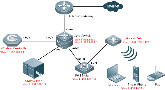
II. Configuration Tips
Configuring Network Infrastructures
4. Finish configuring Internet gateway, Core switch and POE Switch including Vlan 1&2 creation, IP assignment and others required.
4. All wired&wireless devices point gateway to Core Switch.
III. Configuration Steps
On AC:
vlan 1
vlan 2
interface gi0/1
description Link-to-CoreSwitch
switchport mode trunk
switchport trunk allowed vlan remove 3-4094
interface vlan 1
ip address 192.168.1.2 255.255.255.0
interface loopback 0
ip address 1.1.1.1 255.255.255.255
ip route 0.0.0.0 0.0.0.0 192.168.1.1
service dhcp
ip dhcp pool ForAP
network 192.168.1.0 255.255.255.0 192.168.1.128 192.168.1.200
option 138 ip 1.1.1.1
default-router 192.168.1.1
dns-server 8.8.8.8
ip dhcp pool ForUsers
network 192.168.2.0 255.255.255.0
default-router 192.168.2.1
dns-server 8.8.8.8
aaa new-model
aaa group server radius smp
server 192.168.1.3
radius-server host 192.168.1.3 key ruijie
aaa accounting update
aaa accounting update periodic 5
snmp-server enable traps
snmp-server community ruijie rw
ip dhcp snooping
On SMP:
4. Go to Authentication & Authority > Device > Add
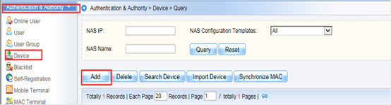

4. Fill in the NAS IP and Choose “Ruijie Wireless device”in the drop-down list. System will prompt “obtaining device information and return a failed message”. It doesn’t matter, because we haven’t set the correct template.


4. Click “View Template” , a new windows pops up displaying current template information, then click “Modify”
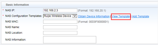
4. Follow below to set according fields:
Identity Authentication Key: ruijie
Web authentication Key : ruijie
SNMP v2c Community : ruijie
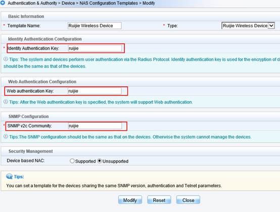
4. Click “Obtain Device information” again, device information is obtained successfully this time.Click “Add”
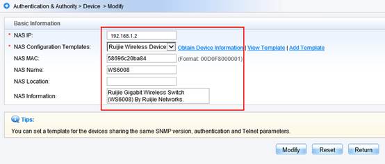
Configuring 802.1x Seamless Authentication
On AC:
aaa accounting network acct-1x start-stop group smp
aaa authentication dot1x auth-1x group smp
wlan-config 10 "802.1x"
ap-group default
interface-mapping 10 2
wlansec 10
security rsn enable
security rsn ciphers aes enable
security rsn akm 802.1x enable
dot1x authentication auth-1x
dot1x accounting acct-1x
On SMP:
Step 1:Configure 802.1x SSID and security parameters
Go to Authentication & Authority > Authentication Settings from the left menu. Enable PEAP Authentication for Windows Client. Fill in the “Auto-connect to SSID”, the value must match with the SSID for 802.1x authentication defined on AC. Choose the Security Type, Encryption Type and Second Stage of PEAP Authentication based on requirement.
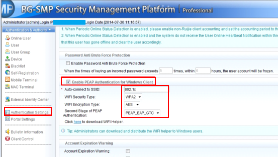
Step 2:Create a new account for testing
Go to Authentication & Authority > Users from the left menu. Add one account for testing purpose, and put this account in Default User Group
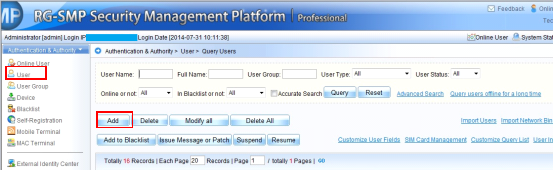
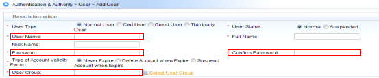
4.1.2.2 Web Seamless Authentication
Overview
Understanding Web Seamless Authentication
Step 1: connects one wireless equipment to SSID “webauth”, authentication portal pops up automatically soon. Fill in username and password. In several seconds, equipment passes authentication, then you can start surfing Internet.
Step 2: Bring the equipment out of wireless coverage, then wireless network interrupts.
Step 3: Bring the authenticated equipment back into the wireless coverage, then this equipment will pass the authentication automatically at the back end, and no more manual intervention is required before you start surfing Internet.
I. Network Topology
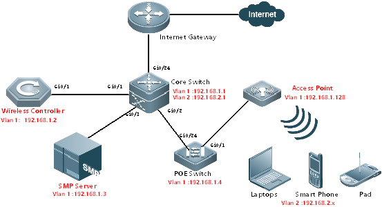
II. Configuration Tips
Configuring Network Infrastructures
4. Finish configuring Internet gateway, Core switch and POE Switch including Vlan 1&2 creation, IP assignment and others required.
4. All wired&wireless devices point gateway to Core Switch.
III. Configuration Steps
On AC:
vlan 1
vlan 2
interface gi0/1
description Link-to-CoreSwitch
switchport mode trunk
switchport trunk allowed vlan remove 3-4094
interface vlan 1
ip address 192.168.1.2 255.255.255.0
interface loopback 0
ip address 1.1.1.1 255.255.255.255
ip route 0.0.0.0 0.0.0.0 192.168.1.1
service dhcp
ip dhcp pool ForAP
network 192.168.1.0 255.255.255.0 192.168.1.128 192.168.1.200
option 138 ip 1.1.1.1
default-router 192.168.1.1
dns-server 8.8.8.8
ip dhcp pool ForUsers
network 192.168.2.0 255.255.255.0
default-router 192.168.2.1
dns-server 8.8.8.8
aaa new-model
aaa group server radius smp
server 192.168.1.3
radius-server host 192.168.1.3 key ruijie
aaa accounting update
aaa accounting update periodic 5
snmp-server enable traps
snmp-server community ruijie rw
ip dhcp snooping
dot1x valid-ip-acct enable
On SMP:
4. Go to Authentication & Authority > Device > Add


4. Fill in the NAS IP and Choose “Ruijie Wireless device”in the drop-down list. System will prompt “obtaining device information and return a failed message”. It doesn’t matter, because we haven’t set the correct template.

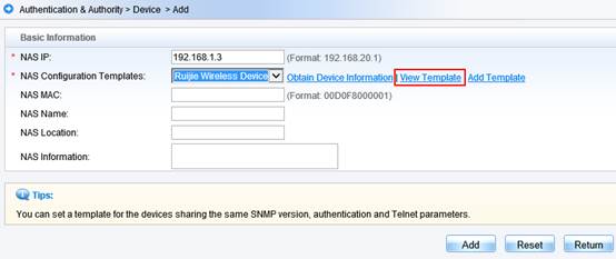
4. Click “View Template”, a new windows pops up displaying current template information, then click “Modify”

4. Follow below to set according fields:
Identity Authentication Key: ruijie
Web authentication Key : ruijie
SNMP v2c Community : ruijie

4. Click “Obtain Device information” again, device information is obtained successfully this time.Click “Add”
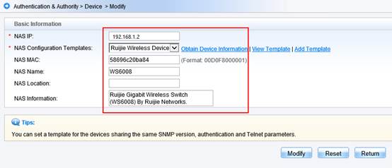
Configuring Web Seamless Authentication
aaa accounting network acct-1x start-stop group smp
aaa authentication dot1x auth-1x group smp
aaa accounting network acct-web start-stop group smp
aaa authentication web-auth auth-web group smp
wlan-config 20 "Ruijie Web Auth"
enable-broad-ssid
ap-group default
interface-mapping 20 2
web-auth template webauth v2
ip 192.168.1.3
url http://192.168.1.3:80/smp/commonauth
wlansec 20
web-auth authentication v2 auth-web
web-auth accounting v2 acct-web
web-auth portal webauth
dot1x authentication auth-1x
dot1x accounting acct-1x
dot1x-mab
webauth
web-auth portal key ruijie
radius-server attribute 31 mac format ietf
snmp-server community ruijie rw
snmp-server enable traps
http redirect direct-site 192.168.2.1 arp
ip dhcp snooping
dot1x valid-ip-acct enable
web-auth acct-update-interval 5
web-auth portal key ruijie
On SMP:
Go to Authentication & Authority > User Group from the left menu. Choose the user group you want to enable MAC authentication. Click Modify. Then click tab Behavior Restrict, enable “An account can register 3 mobile terminals”
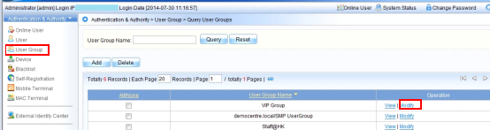
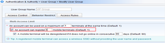
4.1.2.3 QR Code Authentication
Overview
Understanding QR Code Authentication
QR Code authentication feature enables you to scan the QR code of a portal using a QR code reader on your mobile device.
Step 1: Staff passes“802.1x”or “webauth”authentication first
Step 2: Visitors connects to SSID “qrcode”, authentication portal pops up automatically soon, displaying a QRCode Diagram.
Step 3: Staff scans the QR Code, and set the validation period for this temple account (1 day at most).
Step 4: Visitors passes authentication and start surfing.
Note: To use this feature, you need to have a QR code reader app installed on your mobile.
I. Network Topology
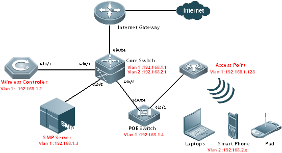
II. Configuration Tips
Configuring Network Infrastructures
4. Finish configuring Internet gateway, Core switch and POE Switch including Vlan 1&2 creation, IP assignment and others required.
4. All wired&wireless devices point gateway to Core Switch.
III. Configuration Steps
On AC:
vlan 1
vlan 2
interface gi0/1
description Link-to-CoreSwitch
switchport mode trunk
switchport trunk allowed vlan remove 3-4094
interface vlan 1
ip address 192.168.1.2 255.255.255.0
interface loopback 0
ip address 1.1.1.1 255.255.255.255
ip route 0.0.0.0 0.0.0.0 192.168.1.1
service dhcp
ip dhcp pool ForAP
network 192.168.1.0 255.255.255.0 192.168.1.128 192.168.1.200
option 138 ip 1.1.1.1
default-router 192.168.1.1
dns-server 8.8.8.8
ip dhcp pool ForUsers
network 192.168.2.0 255.255.255.0
default-router 192.168.2.1
dns-server 8.8.8.8
aaa new-model
aaa group server radius smp
server 192.168.1.3
radius-server host 192.168.1.3 key ruijie
aaa accounting update
aaa accounting update periodic 5
snmp-server enable traps
snmp-server community ruijie rw
ip dhcp snooping
dot1x valid-ip-acct enable
On SMP:
4. Go to Authentication & Authority > Device > Add
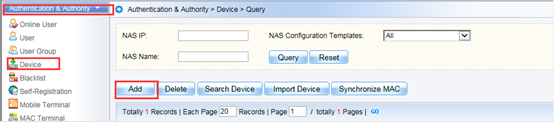
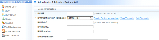
4. Fill in the NAS IP and Choose “Ruijie Wireless device”in the drop-down list. System will prompt “obtaining device information and return a failed message”. It doesn’t matter, because we haven’t set the correct template.
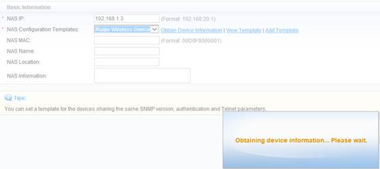

4. Click “View Template”, a new windows pops up displaying current template information, then click “Modify”

4. Follow below to set according fields:
Identity Authentication Key: ruijie
Web authentication Key : ruijie
SNMP v2c Community : ruijie
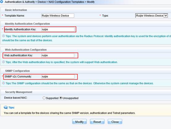
4. Click “Obtain Device information” again, device information is obtained successfully this time.Click “Add”

Configuring QR Code Authentication
aaa accounting network acct-web start-stop group smp
aaa authentication web-auth auth-web group smp
web-auth accounting v2 acct-web
web-auth authentication v2 auth-web
wlan-config 30 "Ruijie QRCode Auth"
enable-broad-ssid
ap-group default
interface-mapping 30 2
web-auth template qrcode v2
ip 172.29.2.4
url http://172.29.2.4:80/smp/qrcodeservlet
wlansec 30
web-auth authentication v2 auth-web
web-auth accounting v2 acct-web
web-auth portal qrcode
webauth
web-auth portal key ruijie
radius-server attribute 31 mac format ietf
snmp-server community ruijie rw
snmp-server enable traps
http redirect direct-site 192.168.2.1 arp
On SMP:
Step 1:Grant employee permission to scan QR code
Go to Authentication & Authority > User Group from the left menu. Click Modify.
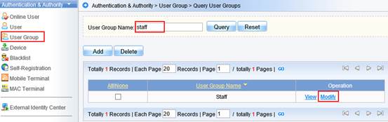
Choose Behavior Restrict,
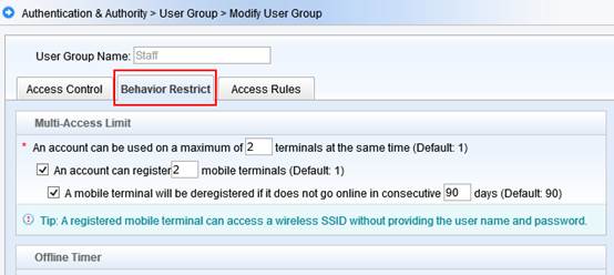
Find the "Guest User Management Rights" option, then enable Allow guest users to access network by scanning a QR Code.
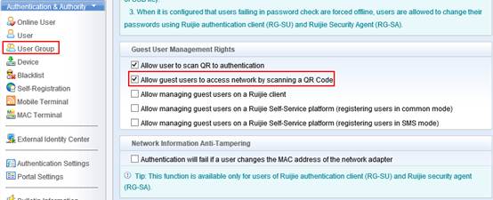
Step 2: Configure portal for QR Code
Go to Authentication & Authority > Portal Settings from the left menu. Click Enable Guest Registration, then Click Enable Guest QR Code Registration. Customize the Message for QR Code Scanning and Message for Successful QR Code Authentication
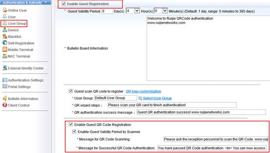
4.1.2.4 SMS Registration Authentication
Overview
Understanding SMS Registration Authentication
Step 1: Visitors connects to SSID “Ruijie SMS Auth”, authentication portal pops up automatically soon.
Step 2: Choose Tab “Visitors Authentication” and fill in the phone number, then click “Acquire sms password”
Step 3: A SMS including password will send to the specified number soon.
Step 4: Visitors fill in the password on authentication portal, then start surfing the Internet
I. Network Topology
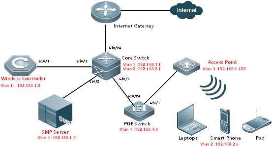
II. Configuration Tips
Configuring Network Infrastructures
4. Finish configuring Internet gateway, Core switch and POE Switch including Vlan 1&2 creation, IP assignment and others required.
4. All wired&wireless devices point gateway to Core Switch.
III. Configuration Steps
On AC:
vlan 1
vlan 2
interface gi0/1
description Link-to-CoreSwitch
switchport mode trunk
switchport trunk allowed vlan remove 3-4094
interface vlan 1
ip address 192.168.1.2 255.255.255.0
interface loopback 0
ip address 1.1.1.1 255.255.255.255
ip route 0.0.0.0 0.0.0.0 192.168.1.1
service dhcp
ip dhcp pool ForAP
network 192.168.1.0 255.255.255.0 192.168.1.128 192.168.1.200
option 138 ip 1.1.1.1
default-router 192.168.1.1
dns-server 8.8.8.8
ip dhcp pool ForUsers
network 192.168.2.0 255.255.255.0
default-router 192.168.2.1
dns-server 8.8.8.8
aaa new-model
aaa group server radius smp
server 192.168.1.3
radius-server host 192.168.1.3 key ruijie
aaa accounting update
aaa accounting update periodic 5
snmp-server enable traps
snmp-server community ruijie rw
ip dhcp snooping
dot1x valid-ip-acct enable
On SMP:
4. Go to Authentication & Authority > Device > Add
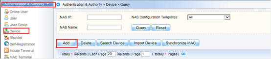

4. Fill in the NAS IP and Choose “Ruijie Wireless device”in the drop-down list. System will prompt “obtaining device information and return a failed message”. It doesn’t matter, because we haven’t set the correct template.


4. Click “View Template” , a new windows pops up displaying current template information, then click “Modify”

4. Follow below to set according fields:
Identity Authentication Key: ruijie
Web authentication Key : ruijie
SNMP v2c Community : ruijie

4. Click “Obtain Device information” again, device information is obtained successfully this time.Click “Add”
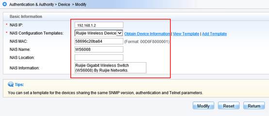
Configuring SMS Registration Authentication
On AC:
aaa accounting network acct-guest start-stop group smp
aaa authentication dot1x auth-guest group smp
wlan-config 40 "Ruijie SMS Auth"
enable-broad-ssid
ap-group default
interface-mapping 40 2
portal-server smsauth ip 192.168.1.3 url http://192.168.1.3:80/smp/commonauth
wlansec 40
web-auth authentication v2 auth-guest
web-auth accounting v2 acct-guest
web-auth portal smsauth
webauth
web-auth acct-update-interval 5
http redirect direct-site 192.168.2.1 arp
web-auth portal key key
radius dynamic-authorization-extension enable
radius-server attribute 31 mac format ietf
snmp-server community ruijie rw
snmp-server enable traps
On SMS Gateway:
Go to SMP Server Windows Device Manager and make sure Driver of GSM-SM Modem has been installed successfully
On SMP:
Step 1: Add SMS gateway on SMP
Go to System Maintenance> SMS Settings from the left menu. Enable SMS Settings, Click Enable SMS Modem. Fill in Port (serial port), Baud Rate, and choose Manufacture Model. Usually, keep the default value of SIM Card PIN Code. After finish configuring, click Send a Test Message to validate.
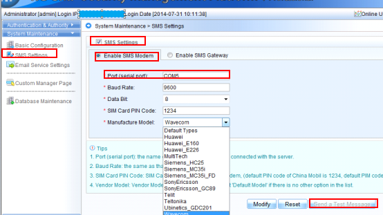
Step 2: Configure built-in portal for SMS Authentication
Go to Authentication & Authority > Portal Settings from the left menu. Click Enable Guest Registration, then Click Enable Guest SMS Self-Service Registration. Customize the SMS Message
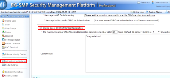
Appendix
5.1 Ruijie Fit AP&AC EWeb Configuration Guide for RGOS 11.x V1.2

If needed, you could find the attachment in our official website with the following download link:
http://www.ruijienetworks.com/service/document/read/57983
5.2 Ruijie Fat AP EWeb Configuration Guide For RGOS 11.x V1.1

If needed, you could find the attachment in our official website with the following download link:
http://www.ruijienetworks.com/service/document/read/57852
5.3 Import license to AC by CLI or WEB
Via CLI:
CD disk license import :
WS6108(config)#set license xxxx-xxxx-xxxx-xxxx-xxxx-xxxx-xxxx-xxxx
Import license file :
(1) Import local license file to AC (Take tftp as an example)
Ruijie#copy tftp://192.168.64.2/LIC-WLAN-AP-800000015692434.lic flash:/LIC-WLAN-AP-800000015692434.lic----> 192.168.64.2 is TFTP server IP address
(2) Install license file
Ruijie#license install flash:LIC-WLAN-AP-800000015692434.lic
Are you sure to install this license[y/n]:y
Success to install license file, service name: LIC-WLAN-AP-8 ----> Succeed to install the license, 8 APs has been increased
Via WEB:
CD disk license import
Access AC WEB homepage, choose 'License' in 'System', and then choose 'Activation Code'. Input activation code, then clicking 'add'. 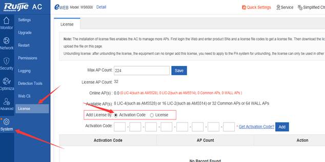
License file import
Access AC WEB homepage, choose 'License' in 'System', and then choose 'License'.
Choose license file location you downloaded in, and then click ‘Install’.
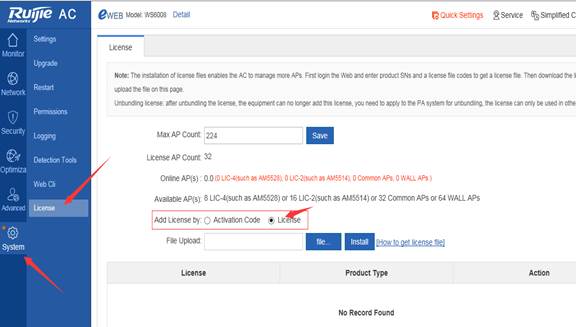
For more details, please find the attachment in our official website with the following download link:
http://www.ruijienetworks.com/support/licensing
5.4 Common Verification Commands
This section lists some common verification commands on AC, remember to collect these information and share to Ruijie Postsales when you encounter problem and ask for help.
Command list
5. show cpu
5. show memory
5. show running-config
5. show version
5. show ap-config summary
5. show ac-config client
5. show dot11 associations all-client
show cpu
Generally, for "CPU utilization in five minutes" as a reference, AC works properly when CPU utilization below 80%
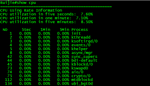
show memory
Generally, AC works properly when Memory utilization below 80%.
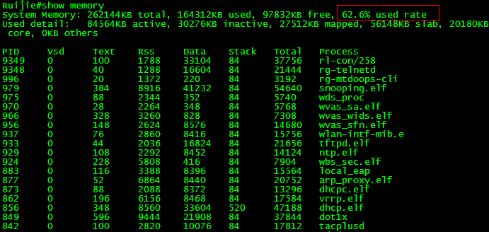
show running-config
Display AC configuration
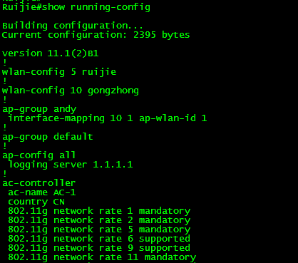
Dispaly AP configuration on AC
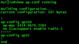
show version
Generally, you can check time, software and hardware verion when execute this command "show version"
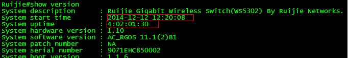
show ap-config summary
It's a useful command, you can view below informations:
5. Online AP number
5. AP name
5. AP IP & MAC address
5. AP Radio status (enable or not, which channel, the power percentage)
5. The user number AP carries
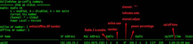
show ac-config client
It's a useful command, you can view below informations:
5. Current user number AC is carrying
5. Wireless user IP & MAC address
5. Authentication method
5. The AP & WLAN wireless user is connected.
.............
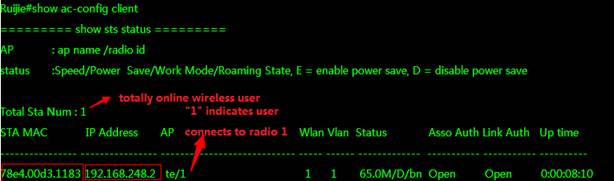
show dot11 associations all-client
Execute this command on AP(No matter FAT or Fit), display wireless user informations.
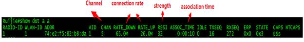
"RSSI" = 32 indicates 32-95 = -63 dBm.
Usually, if the value is bigger than -75dBm, it is a good wireless strength; if the value is smaller than -75dBm, user may have packet loss and bad experience.
-63dBm is bigger than -75dBm, so user will have good experience.