Ruijie WLAN PoC Guide (V1.1)


Test Content
1. Basic Setup
1.1 Central Forwarding
| Test Item | Central Forwarding |
| Description | The test AP establishes CAPWAP tunnel with the AC using Central Forwarding mode |
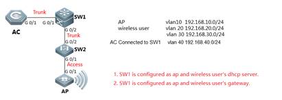
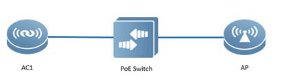
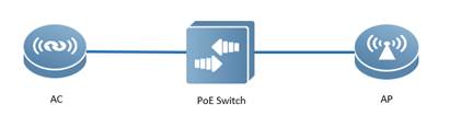
| Test Procedure | Topology:
Procedure: 1) Configure AC Step1: config Vlan, include user vlan and interconnect vlan, Ruijie>enable Ruijie#configure terminal Ruijie(config)#vlan 20 ------>user vlan Ruijie(config-vlan)#name sta Ruijie(config-vlan)#exit Ruijie(config)#vlan 30 ------>user vlan Ruijie(config-vlan)#name sta Ruijie(config-vlan)#exit Ruijie(config)#vlan 40 ------>interconnect vlan for ac and sw1 Ruijie(config-vlan)#exit Ruijie(config)#interface vlan 20 ------>user interface vlan(must config) Ruijie(config-int-vlan)#ip add 192.168.20.2 255.255.255. Ruijie(config)#interface vlan 30 ------>user interface vlan(must config) Ruijie(config-int-vlan)#ip add 192.168.30.2 255.255.255.0 Ruijie(config-int-vlan)#exit
Step2:Config ssid (multi ssid) Ruijie(config)#wlan-config 1 Ruijie1 Ruijie(config-wlan)#enable-broad-ssid ------->enable broadcast ssid Ruijie(config-wlan)#exit Ruijie(config)#wlan-config 2 Ruijie2 Ruijie(config-wlan)#enable-broad-ssid ------->enable broadcast ssid Ruijie(config-wlan)#exit
Step3:Config ag-group Ruijie(config)#ap-group default Ruijie(config-ap-group)#interface-mapping 1 20 ------->associate wlan-config 1 with user vlan 30 Ruijie(config-ap-group)#interface-mapping 2 30 ------->associate wlan-config 2 with user vlan 30 Ruijie(config-ap-group)#exit
Step4:Config svi and routing Ruijie(config)#ip route 0.0.0.0 0.0.0.0 192.168.40.1 ------->default routing to sw1 Ruijie(config)#interface vlan 40 ------->interconnect vlan with sw1 Ruijie(config-int-vlan)#ip address 192.168.40.2 255.255.255.0 Ruijie(config-int-vlan)#exit Ruijie(config)#interface loopback 0 Ruijie(config-int-loopback)#ip address 1.1.1.1 255.255.255.0 ------->AC initialize CAPWAP tunnel setup from loopback 0 interface Ruijie(config-int-loopback)#exit Ruijie(config)#interface GigabitEthernet 0/1 Ruijie(config-int-GigabitEthernet 0/1)#switchport mode trunk ------->connect to sw1, trunk port, allow user vlan、AP vlan、AC-to-SW1 vlan
Step5:Save config Ruijie(config-int-GigabitEthernet 0/1)#end Ruijie#write
2) Configure core switch(SW1) Step1:Vlan config, config user vlan, ap vlan and interconnect vlan Ruijie>enable Ruijie#configure terminal Ruijie(config)#vlan 10 ------>ap vlan Ruijie(config-vlan)#exit Ruijie(config)#vlan 20 ------>user vlan Ruijie(config-vlan)#exit Ruijie(config)#vlan 30 ------>user vlan Ruijie(config-vlan)#exit Ruijie(config)#vlan 40 ------>interconnect vlan with AC Ruijie(config-vlan)#exit
Step2:Config interface and svi Ruijie(config)# interface GigabitEthernet 0/1 Ruijie(config-int-GigabitEthernet 0/1)#switchport mode trunk ------->uplink port, connect to AC, trunk port,allow user vlan、AP vlan、AC-to-SW1 vlan Ruijie(config-int-GigabitEthernet 0/1)#exit Ruijie(config)#interface GigabitEthernet 0/2 Ruijie(config-int-GigabitEthernet 0/2)#switchport mode trunk ------->downlink port, connect to SW2,trunk port,allow user vlan、AP vlan Ruijie(config-int-GigabitEthernet 0/2)#exit Ruijie(config)#interface vlan 10 ------>ap gateway Ruijie(config-int-vlan)#ip address 192.168.10.1 255.255.255.0 Ruijie(config-int-vlan)#interface vlan 20 ------->sta gateway Ruijie(config-int-vlan)#ip address 192.168.20.1 255.255.255.0 Ruijie(config-int-vlan)#interface vlan 30 ------->sta gateway Ruijie(config-int-vlan)#ip address 192.168.30.1 255.255.255.0 Ruijie(config-int-vlan)#interface vlan 40 ------->interconnect with ac Ruijie(config-int-vlan)#ip address 192.168.40.1 255.255.255.0 Ruijie(config-int-vlan)#exit
Step3:Conifg ip dhcp server Ruijie(config)#service dhcp Ruijie(config)#ip dhcp pool ap_ruijie ------->create dhcp pool for ap,pool name is ap_ruijie Ruijie(config-dhcp)#option 138 ip 1.1.1.1 ------->config option 138, assign ac loopaback 0 ip address Ruijie(config-dhcp)#network 192.168.10.0 255.255.255.0 ------->assign these address to ap Ruijie(config-dhcp)#default-route 192.168.10.1 ------->assign the gateway to ap Ruijie(config-dhcp)#exit Ruijie(config)#ip dhcp pool user_ruijie1 ------->create dhcp pool for sta,pool name is user_ruijie Ruijie(config-dhcp)#network 192.168.20.0 255.255.255.0 ------->assign these address to sta Ruijie(config-dhcp)#default-route 192.168.20.1 ------->assign the gateway to sta Ruijie(config-dhcp)#dns-server 8.8.8.8 ------->assign the dns to sta Ruijie(config-dhcp)#exit Ruijie(config)#ip dhcp pool user_ruijie2 ------->create dhcp pool for sta,pool name is user_ruijie Ruijie(config-dhcp)#network 192.168.30.0 255.255.255.0 ------->assign these address to sta Ruijie(config-dhcp)#default-route 192.168.30.1 ------->assign the gateway to sta Ruijie(config-dhcp)#dns-server 8.8.8.8 ------->assign the dns to sta Ruijie(config-dhcp)#exit Step4:Config static routing Ruijie(config)#ip route 1.1.1.1 255.255.255.255 192.168.40.2 ------->config static route, route to AC loopback0
Step5:Save configuration Ruijie(config)#exit Ruijie#write
3) Configure access switch (SW2) Step1:Config vlan, create ap vlan Ruijie>enable Ruijie#configure terminal Ruijie(config)#vlan 10 Ruijie(config-vlan)#exit
Step2:Config interface Ruijie(config)#interface GigabitEthernet 0/1 Ruijie(config-int-GigabitEthernet 0/1)#switchport access vlan 10 ------->connect to AC, access port, allow ap vlan Ruijie(config-int-GigabitEthernet 0/1)#exit Ruijie(config)#interface GigabitEthernet 0/2 Ruijie(config-int-GigabitEthernet 0/2)#switchport mode trunk ------->connect to SW1, trunk port
Step3:Save configuration Ruijie(config-int-GigabitEthernet 0/2)#end Ruijie#write |
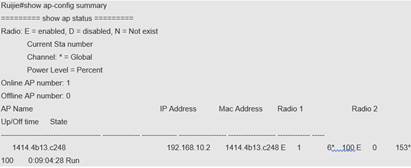
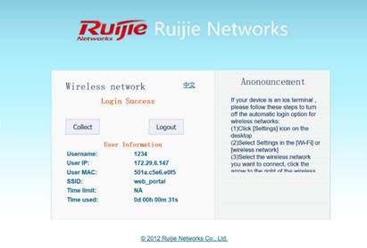
| Expected Result: | 1) STA will be able to connect to the SSID 2) The AP and AC CAPWAP tunnel is established:
|
| Test Conclusion: |
|
1.2 Local Forwarding
| Test Item | Local Forwarding |
| Description | The test AP establishes CAPWAP tunnel with the AC using Local Forwarding mode |
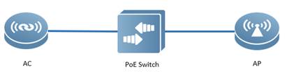
| Test Procedure | Procedure: 1) The AP establishes CAPWAP Tunnel with the AC (See above test procedure)
2) Configure the access switch POESwtich(config)#interface gigabitEthernet 0/2 ---> the port connects to AP POESwtich(config-GigabitEthernet 0/2)#switchport mode trunk POESwtich(config-GigabitEthernet 0/2)#switchport trunk native vlan 10 --->10 is AP’s management Vlan POESwtich(config-GigabitEthernet 0/2)#switchport trunk allowed vlan remove 1-9,11-19,21-4094 --->Prune all VLANs except for AP management Vlan and user data Vlan
3) Configure the AC AC(config)#wlan-config 1 ruijie AC(config-wlan)#tunnel local ----->enable local forwarding in WLAN 1 AC(config)#ap-group ruijie AC(config-ap-group)#no interface-mapping 1 10 ----->all wireless user under this ap-group will be forced offline AC(config-ap-group)#interface-mapping 1 10 --->Reassociate WLAN ID and VLAN ID to make configuration effect
|
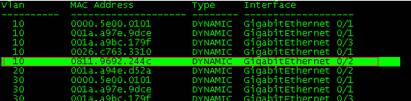
| Expected Result: | The PoE Switch learns the MAC address of wireless users on the downlink port that connects to AP (on Central forwarding mode, the access switch won’t learn the user’s MAC address since the user data is encapsulated in CAPWAP tunnel)
POESwtich(config)#show mac-address-table
|
| Test Conclusion: |
|
1.3 Fat Mode
| Test Item | Fat Mode |
| Description | AP switches to FAT mode and broadcast SSIDs |
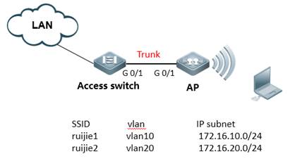
| Test Procedure | Topology:
Procedure: Step1: Connect console Default password:ruijie
Step2: Set AP mode fat Default mode:fit Ruijie>ap-mode fat
Step3:Create VLAN and dhcp server (ignore dhcp configuration when using other dhcp server) Ruijie>enable Ruijie#configure terminal Ruijie(config)#vlan 1 Note:VLAN 1 is only of local meaning Ruijie(config-vlan)#vlan 10 ------>create user vlan10 Ruijie(config-vlan)#vlan 20 ------>create user vlan20 Ruijie(config)#service dhcp ------>enable dhcp service Ruijie(config)#ip dhcp excluded-address 172.16.10.253 172.16.10.254 ------>these address will not assign to user Ruijie(config)#ip dhcp excluded-address 172.16.20.253 172.16.20.254 Ruijie(config)#ip dhcp pool test_10 ------>config dhcp pool named with test_10 Ruijie(dhcp-config)#network 172.16.10.0 255.255.255.0 Ruijie(dhcp-config)#dns-server 218.85.157.99 Ruijie(dhcp-config)#default-router 172.16.10.254 Ruijie(dhcp-config)#exit Ruijie(config)#ip dhcp pool test_20 ------>config dhcp pool named with test_20 Ruijie(dhcp-config)#network 172.16.20.0 255.255.255.0 Ruijie(dhcp-config)#dns-server 218.85.157.99 Ruijie(dhcp-config)#default-router 172.16.20.254
Step4: Configure dot1q Ruijie(config)#interface GigabitEthernet 0/1 Ruijie(config-if)#encapsulation dot1Q 1 Ruijie(config)#interface GigabitEthernet 0/1.10 Ruijie(config-if)#encapsulation dot1Q 10 Ruijie(config)#interface GigabitEthernet 0/1.20 Ruijie(config-if)#encapsulation dot1Q 20
Step5: Configure SSID Ruijie(config)#dot11 wlan 10 Ruijie(dot11-wlan-config)#broadcast-ssid Ruijie(dot11-wlan-config)#ssid ruijie1 Ruijie(config)#dot11 wlan 20 Ruijie(dot11-wlan-config)#broadcast-ssid Ruijie(dot11-wlan-config)#ssid ruijie2
Step6: Configure Radio interface Ruijie(config)#interface Dot11radio 1/0.1 Ruijie(config-if-Dot11radio 1/0.1)#encapsulation dot1Q 1 Ruijie(config)#interface Dot11radio 1/0.10 Ruijie(config-if-Dot11radio 1/0.10)#encapsulation dot1Q 10 ------>encapsulation vlan 10 Ruijie(config)#interface Dot11radio 1/0.20 Ruijie(config-if-Dot11radio 1/0.20)#encapsulation dot1Q 20 ------>encapsulation vlan 20 Ruijie(config)#interface Dot11radio 2/0.10 Ruijie(config-if-Dot11radio 2/0.10)#encapsulation dot1Q 10 ------>encapsulation vlan 10 Ruijie(config)#iinterface Dot11radio 2/0.20 Ruijie(config-if-Dot11radio 2/0.20)#encapsulation dot1Q 20 ------>encapsulation vlan 20
Step7:Associate SSID Ruijie(config)#interface Dot11radio 1/0 Ruijie(config-if-Dot11radio 1/0)#wlan-id 10 Config interface wlan id:10, SSID:ruijie1 // success log Ruijie(config)#interface Dot11radio 1/0.1 Ruijie(config-if-Dot11radio 1/0.1)#wlan-id 20 Config interface wlan id:20, SSID:ruijie2 // success log Ruijie(config)#interface Dot11radio 2/0 Ruijie(config-if-Dot11radio 2/0)#wlan-id 10 Config interface wlan id:10, SSID:ruijie1 // success log Ruijie(config)#interface Dot11radio 2/0.1 Ruijie(config-if-Dot11radio 2/0.1)#wlan-id 20 Config interface wlan id:20, SSID:ruijie2 // success log
Step8:Configure MGMT IP and routing Ruijie(config)#interface BVI 1 ------>configure MGMT IP address,vlan 1 map bvi 1 Ruijie(config-if)#ip address 172.16.1.253 255.255.255.0 Ruijie(config)#interface bvi 10 Ruijie(config-if-BVI 10)#ip address 172.16.10.253 255.255.255.0 Ruijie(config)#interface bvi 20 Ruijie(config-if-BVI 20)#ip address 172.16.20.253 255.255.255.0 Ruijie(config)#ip route 0.0.0.0 0.0.0.0 172.16.1.254 Ruijie(config)#end Ruijie#write
Step9:Config switch Access_switch: Access_switch(config)#vlan 1 Access_switch(config-vlan)#exit Access_switch(config)#interface vlan 1 Access _switch(config-VLAN 1)#ip address 172.16.1.254 255.255.255.0 Access_switch(config)#interface vlan 10 Access_switch(config-VLAN 10)#ip address 172.16.10.254 255.255.255.0 Access_switch(config)#interface vlan 20 Access_switch(config-VLAN 20)#ip address 172.16.20.254 255.255.255.0 Access_switch(config-VLAN 20)#exit Access_switch(config)#interface gigabitEthernet 0/1 // downlink to AP Access_switch(config-GigabitEthernet 0/1)#switchport mode trunk Access_switch(config)#interface gigabitEthernet 0/2 //access switch uplink Access_switch(config-GigabitEthernet 0/2)#switchport mode trunk
|
| Expected Result: | STAs are able to connect the SSID and ping to their gateway |
| Test Conclusion: |
|
1. Common Function
1.1 Rate Limit
| Test Item | Rate Limit |
| Description | Limit the average data rate and burst data rate to each wireless user connected to the AP |
| Test Procedure | Procedure: 1) The AP establishes CAPWAP Tunnel with the AC (See above test procedures)
2) Configure AC: Ruijie(config)#ap-config AP Ruijie(config-ap)#ap-based per-user-l imit down-streams average-data-rate 800 burst-data-rate 1600
Attention: The unit is 8K Bit = 1K Byte. |
| Expected Result: | 1. Connect to wlan and have a speed test 2. The average speed rate will be limited to 800KBps |
| Test Conclusion: |
|
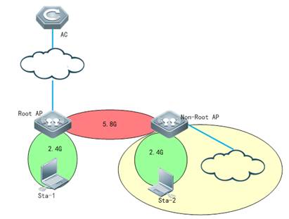
1.2 Wireless Bridge
| Test Item | Wireless Bridge |
| Description | A wireless tunnel will be established between 2 APs |
| Test Procedure | Topology:
Note: only outdoor Aps support wireless bridge Procedure: 1) Make sure that Root AP has established capwap tunnel with AC, verify by following command in controller: Ruijie#sh capwap state CAPWAP tunnel state, 1 peers, 1 is run: Index Peer IP PortState 1 110.10.10.10 5246 Run
2) Configure Root-AP by using following command on controller: AC(config)#wlan-config 100 wds-test-root ------>configure a special ssid for wds AC(config-wlan)#exit AC(config)#wlan-config 200 wds-test-2.4G------>Configure assid for 2.4g signal cover AC(config-wlan)#exit AC(config)#vlan 100 ------>Configure vlan for wds AP AC(config-vlan)#exit AC(config)#vlan 200 ------>Configure vlan for clients AC(config-vlan)#exit AC(config)#int vlan 100 ------>Configure dhcp pool for wds AP AC(config-if-VLAN 100)#ip address 90.0.100.254 255.255.255.0 AC(config-if-VLAN 100)#exit AC(config)#int vlan 200 ----->Configure dhcp pool for clients AC(config-if-VLAN 200)#ip address 90.0.200.254 255.255.255.0 AC(config-if-VLAN 200)#exit AC(config)#ip dhcp pool vlan-100 AC(dhcp-config)#network 90.0.100.0 255.255.255.0 AC(dhcp-config)#default-router 90.0.100.254 AC(dhcp-config)#option 138 ip 10.10.10.10 AC(dhcp-config)#exit AC(config)#ip dhcp pool vlan-200 AC(dhcp-config)#network 90.0.200.0 255.255.255.0 AC(dhcp-config)#default-router 90.0.200.254 AC(dhcp-config)#dns-server 192.168.58.110 AC(dhcp-config)#exit AC(config)#service dhcp ----->enable dhcp service AC(config)#ap-group wds ---------> configure a new ap-group to associate the wlan-id and vlan AC(config-group)#interface-mapping 100 100 radio 2 AC(config-group)#interface-mapping 200 200 radio 1 AC(config-group)#exit AC(config)#ap-config ap630 -------> configure the AP which needs to be set as Root-AP in WDS AC(config-ap)#ap-group wds AC(config-ap)#station-role root-bridge bridge-wlan 1 radio 2 AC(config-ap)#end AC#write
3) Configure the non-root Ap
Change AP to fat-mode Ruijie#conf Ruijie#(config)ap-mode fat Connect AP (with ip add 192.168.110.1), and run the following command in this AP: Ruijie#conf Ruijie(config)#int dot11radio 2/0 Ruijie(config-if-Dot11radio 2/0)#station-role non-root-bridge Ruijie(config-if-Dot11radio 2/0)#parent ssid wds-test-root ------> bridge SSID Ruijie(config-if-Dot11radio 2/0)#wds pre-config create Ruijie(config-if-Dot11radio 2/0)#exit Change the AP to fit mode Ruijie#conf Ruijie#(config)ap-mode fit ----->change AP to fit mode, then ap will reload automatically, the WDS will be set up successfully.
|
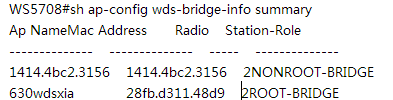
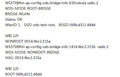
| Expected Result: | 1) the bridge status will be shown on the controller AC#show ap-config wds-bridge summary
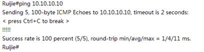
2) The ping from non-root AP to root AP will be successful
|
| Test Conclusion: |
|
1.3 AP load balance
| Test Item | AP load balance |
| Description | Load balancing based on the number of users |
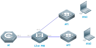
| Test Procedure | Topology:
Note: AP need to broadcast the same SSID signal. Procedure: 1) Create a number-based balancing group on the AC, named test1. Ruijie(config)#ac-controller Ruijie(config-ac)#num-balance-group create test1
2) Configure the load balance threshold Ruijie(config-ac)#num-balance-group num test1 1 -----> when the difference of more than 1 STAs on APs, the AP which carries more users will not response new associations.
3) Add APs to the load balance group Ruijie(config-ac)#num-balance-group add test1 ap320-1 ---->put AP named ap320-i into load balance group Ruijie(config-ac)#num-balance-group add test1 ap320-2
|
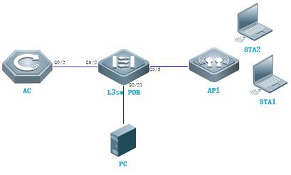
| Expected Result: | 1) The load balance state will be shown on AC
2) Perform the following step: 1. Before configuring the load balancing, associate STA1 and STA2 with the network. Run show ac-config client to confirm that STA1 and STA2 are associated with AP1. 2. Get STA1 and STA2 offline. Configure the load balancing group based on the number of users. 3. Associate STA1 with the network. Run show ac-config client to confirm that STA1 is associated with AP1. 4. Associate STA2 with the network. The STA2 is associated with the network in a short period of time. Run show ac-config client to confirm that STA2 is associated with AP2 |
| Test Conclusion: |
|
1.4 Remote Intelligent PerceptiveTechnology (RIPT)
| Test Item | Remote Intelligent Perceptive Technology (RIPT) |
| Description | When the CAPWAP tunnel between AP and AC is down, the AP is still able to transfer user data normally. |
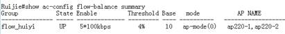
| Test Procedure | Topology:
Procedure: 1) The AP establishes CAPWAP Tunnel with the AC (See above test procedure)
2) configure RIPT as below steps: 1. Configure escape SSID Ruijie(config)#wlan-config 10 "escape SSID" Ruijie(config-wlan)#tunnel local Ruijie(config-wlan)# enable-ssid at-capwap-down 2. Enable RIPT under AP group configuration mode Ruijie(config)#ap-group default Ruijie(config-group)#ript enable
|
| Expected Result: | 1. Ping the PC from STA 2. Shutdown the physical interface of AC 3. STA is still be able to ping the PC |
| Test Conclusion: |
|
1.5 AC Virtualization (VAC)
| Test Item | AC Virtualization (VAC) |
| Description | Multiple ACs will be virtualized into one logical AC |
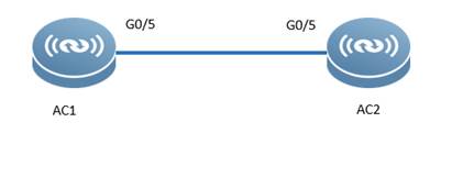
| Test Procedure | Topology:
Procedure:
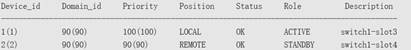
Configure the AC1: AC(config)#virtual-ac domain 90 # The domain ID is a digit. The same domain ID must be configured for each AC. AC(config-vac-domain)#device 1 # Specify the device ID of the AC. AC(config-vac-domain)#device 1 priority 100 # A higher priority indicates a higher probability of being selected as the active AC. AC(config-vac-domain)#exit AC(config)# vac-port AC(config-vac-port)#port-member interface gigabitEthernet 0/5 # Specify VSL ports. On the WS card, specify TE ports as VSL ports. Configure the AC2 AC(config)#virtual-ac domain 90 AC(config-vac-domain)#device 2 # Specify the device ID of the AC. AC(config-vac-domain)#device 2 priority 90 AC(config-vac-domain)#exit AC(config)# vac-port AC(config-vac-port)#port-member interface gigabitEthernet 0/5 Switch the 2 ACs to the VAC mode AC#write AC#device convert mode virtual Convert mode will backup and delete config file, and reload the switch. Are you sure to continue[yes/no]:yes Do you want to recover config file from backup file in virtual mode (press 'ctrl + c' to cancel) [yes/no]:yes
|
| Expected Result: | Run show virtual-ac command, each AC’s information will be displayed.
|
| Test Conclusion: |
|
1. Security Function
1.1 Wireless Encryption (WPA/WPA2)
| Test Item | Wireless Encryption (WPA/WPA2) |
| Description | Wireless user needs to input password when connect to wireless network. |
| Test Procedure | Topology:
Procedure: 1. WPA configuration WS5708(config)#wlansec 1 WS5708(config-wlansec)#security wpa enable WS5708(config-wlansec)#security wpa ciphers aes enable WS5708(config-wlansec)#security wpa akm psk enable WS5708(config-wlansec)#security wpa akm psk set-key ascii 1234567890 ---->wifi password, no less than 8 digits
2. WPA2 configuration WS5708(config)#wlansec 1 WS5708(config-wlansec)#security rsn WS5708(config-wlansec)#security rsn ciphers aes WS5708(config-wlansec)#security rsn akm psk WS5708(config-wlansec)#security rsn akm psk set-key ascii 1234567890 ---->wifi password, no less than 8 digits Note: One SSID can support both WPA and WPA2, but two passwords MUST match.
|
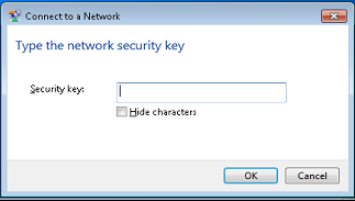
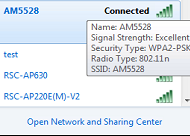
| Expected Result: | 1. when connecting the SSID, the security key authentication is required
2. type in the right security key, the STA can connect wireless network successfully
|
| Test Conclusion: |
|
1.2 Private Pre-Shared Key (PPSK)
| Test Item | Private Pre-Shared Key (PPSK) |
| Description | Different STAs uses different passwords to connect the same SSID |
| Test Procedure | Topology:
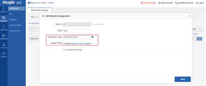
Procedure: 1) Enabling the PPSK On the AC’s Web page, choose Network > WiFi/WLAN, select WPA/WPA2-PSK, and select Enable PPSK.
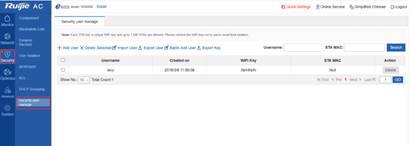
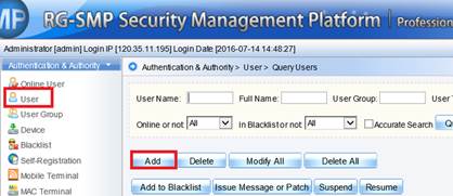
2) PPSK Account Management On the Web page, choose Security > Security user manage. The following figure shows the effect of importing user names.
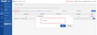
3) Add users Click Add User. The following dialog box is displayed. Enter the user name. A random 8-character key is automatically generated. Add at least 2 users for testing.
|
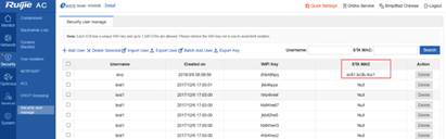
| Expected Result: | Connect 2 STAs to the SSID with different passwords. After STAs authentication succeed, the STAs MAC address will be displayed on the Security user manage page.
|
| Test Conclusion: |
|
1.3 Blacklist & Whitelist
| Test Item | Blacklist & Whitelist |
| Description | When blacklist is enabled, STAs within the blacklist cannot access the wireless network. When whitelist is enabled, only STAs within the whitelist ca access the wireless network. |
| Test Procedure | Topology:
Procedure: Blacklist: WS5302(config)#wids WS5302(config-wids)#static-blacklist mac-address 6809.27b0.169f ----->6809.27b0.169f is denied to access
Whitelist: WS5302(config)#wids WS5302(config-wids)#whitelist mac-address 6809.27b0.169f -----> only 6809.27b0.169f is allowed to access |
| Expected Result: | 1. if blacklist is enabled, the STA with MAC address 6809.27b0.169f cannot connect to the network. 2. if whitelist is enabled, all STAs except 6809.27b0.169f cannot connect to the network. |
| Test Conclusion: |
|
1.4 AP Countermeasure
| Test Item | AP Countermeasure |
| Description | Ruijie AP interferes with STAs connecting to APs from other vendors |
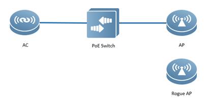
| Test Procedure | Topology:
Note: Ruijie AP will not countermeasure Ruijie AP by default. Recommend to use AP from the other vendor as the Rogue AP Procedure:
1) Configure AP as monitor mode AC(config)# ap-config ap220-e AC(ap-config)# device mode monitor
2) Configure countermeasure rogue ap static list AC(config)#wlan-config 5 monitor AC(config-wlan)#no enable-broad-ssid AC(config-wlan)#exit AC(config)#ap-group Countermeasure AC(config-group)#interface-mapping 5 1 AC(config-group)#exit AC(config)# ap-config ap220-e AC(config-ap)#ap-group Countermeasure AC(config-ap)#scan-channels 802.11b channels 1 2 3 4 5 6 7 8 9 10 11 12 13 --->configure the scanning channel of 2.4G AC(config-ap)#scan-channels 802.11a channels 149 153 157 161 165 --->configure the scanning channel of 5G AC(config)#wids ----->enter wids mode AC(config-wids)#countermeasure enable ----->enable countermeasure AC(config-wids)#countermeasures channel-match ----->enable channel-based containment AC(config-wids)#countermeasures mode config ----->choose the countermeasures mode AC(config-wids)#device attack mac-address 061b.b120.700c -----> add rogue AP bssid:061b.b120.700c. you can scan rogue AP with Wirelessmon to get the bssid. Ruijie(config-wids)#countermeasures interval 20
|
| Expected Result: | When STAs connect to the SSID that rogue AP broadcasts, there will be significant packets drop and disconnection. |
| Test Conclusion: |
|
1.5 User Isolation
| Test Item | User Isolation |
| Description | Wireless users connect to same AP cannot get access to each other |
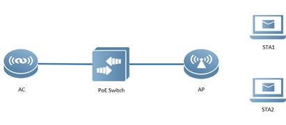
| Test Procedure | Topology:
Procedure: Isolate user associated to the same AP AC(config)#wids AC(config-wids)#user-isolation ap enable
|
| Expected Result: | Connect 2 STAs to the AP, they cannot ping from each other |
| Test Conclusion: |
|
1.6 802.1x Authentication
| Test Item | 802.1x Authentication |
| Description | 802.1x authentication is required to connect the wireless network |
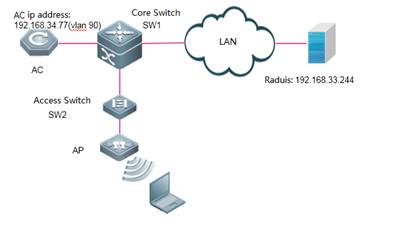
| Test Procedure | Topology:
Procedure:
1. Enable 802.1x AAA authentication AC-1(config)#aaa new-model ---->enable AAA authentication AC-1(config)#aaa authentication dot1x default group radius ---->define the default group of dot1x authentication AC-1(config)#aaa accounting network default start-stop group radius ---->define the default group of aaa accounting
2. Configure Radius server's IP addrsess and KEY AC-1(config)#radius-server host 192.168.33.244 key ruijie ----> configure ip address and key of radiius server AC-1(config)#ip radius source-interface bvi 90 ----> AC communicate with radius using the IP address of vlan 90
3. Configure parameters of 802.1x authentication AC-1(config)#dot1x authentication default ----> use default list for dot1x authentication AC-1(config)#dot1x accounting default ----> use default list for dot1x accounting AC-1(config)#dot1x eapol-tag ----> make AC able to process authentication packets with VLAN tag
4. Enable 802.1X authentication AC-1(config)#wlansec 1 ----> enable authentication on wlan 1 AC-1(config-wlansec)# security rsn enable AC-1(config-wlansec)# security rsn ciphers aes enable AC-1(config-wlansec)# security rsn akm 802.1x enable
5. Configure SNMP AC-1(config)#snmp-server host 192.168.33.244 traps version 2c ruijie AC-1(config)#snmp-server enable traps AC-1(config)#snmp-server community ruijie rw
6. Configure radius server //the configuration may vary with different radius, here we take Ruijie SMP server as an example:
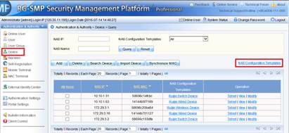
1) Login to SMP server ---> "Authentication & Authority" ---> "Device" ---> "NAS Configuration Templates"
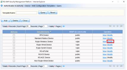
2) Choose "Ruijie Wireless Device", and click "Modify"
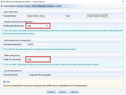
3) Configure "Identify Authentication Key" and "SNMP v2c Community"
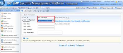
4) Add new device, fill in the IP address of the AC, and select "Ruijie Wireless Device" as configuration Templates
5) Add a new user
|
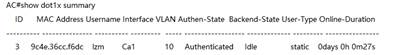
| Expected Result: | 1. The STA is able to connect to the SSID with configured username and password 2. "show dot1x summary" command shows online users
|
| Test Conclusion: |
|
1.7 Web Authentication
| Test Item | Web Authentication |
| Description | Web authentication is required to connect the wireless network |
| Test Procedure | Topology:
Procedure: 1. Configuring AAA AC(config)#aaa new-model ---->enable AAA authentication AC(config)#aaa accounting network default start-stop none ---->disable aaa accounting AC(config)#aaa authentication iportal default local ----> authenticaticate with local accounts 2. Configuring local accounts AC(config)#username admin web-auth password admin ------>configure local username and password 3. Bypass arp packets of wireless user gateway AC(config)#http redirect direct-arp 192.168.51.1 ------>192.168.51.1 is wireless users' gateway 4. Enable https AC(config)#http redirect port 443 5. Configuring Wlansec AC(config)#web-auth template iportal AC(config)#wlansec AC(config-wlansec)#web-auth portal iportal AC(config-wlansec)#webauth |
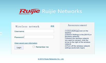
| Expected Result: | 1. Connect to wireless ssid, the authentication page will pops up.
2. input the correct username/password, the authentication succeeds.
|
| Test Conclusion: |
|
1. Performance
1.1 AP Throughput Performance
| Test Item | AP Throughput Performance |
| Description | Test the AP’s max throughput performance |
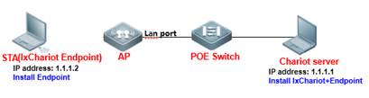
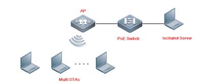
| Test Procedure | Topology:
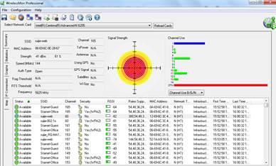
Procedure: 1. Test Environment Check Use a signal scanning tool such as WirelessMon to scan the onsite environment. If the interference from other service set identifiers (SSIDs) is detected, these SSIDs should be turned off; if they cannot be turned off, the test should avoid the channel where a SSID of strong signal interference is located.
Before the test, you can also use WirelessMon to scan the RSSI of the test SSID to ensure that the RSSI is not smaller than –55 dBm.
When there is any interference in the test environment, configure the AP channel to the one with the smallest interference. AC#conf AC(config)#ap-config AP530----- The AP name is AP530. AC(config-ap)#channel 11 radio 1 ---- Change RF interface 1 to Channel 11. AC(config-ap)#end
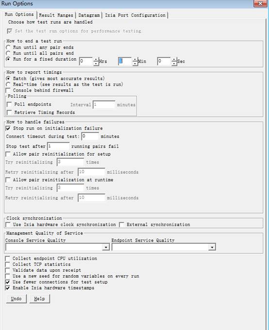
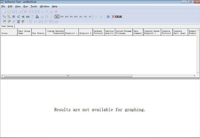
2. Install IxChariot IxChariot is the industry's leading test tool for simulating real-world applications and assessing network performance in live networks. IxChariot uses distributed, low-profile endpoint to assess point to point performance and network capacity. It can be used to test the highest performance of an AP, thereby obtaining the its upstream and downstream throughput (official website of IxChariot: http://www.ixiacom.com).
Components of IxChariot: ① IxChariot Console: It is installed in the Windows system to generate and simulate traffic, and output the data simulation result. ② Endpoint: It is installed in the Windows system to send and receive traffic.
Step1: Install IxChariot 6.7 (both the Console and Endpoint) on the server. Step2: Install Endpoint on STAs Step3: Start IxChariot
Note: On the server, you should ensure proper running of both the Console and Endpoint, but on an STA, you need to ensure only proper running of the Endpoint.
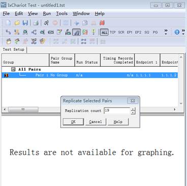
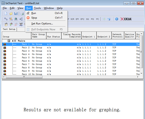
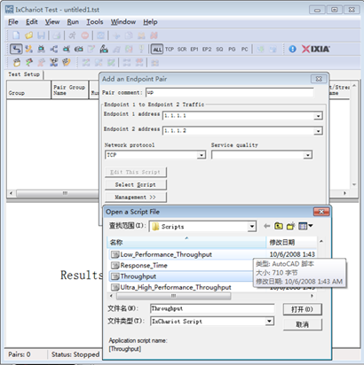
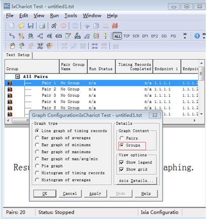
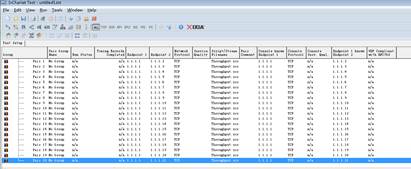
3. Create a downward data sending stream, and send data from Serve 1.1.1.1 to STA 1.1.1.2. Click
4. Create 20 data streams.
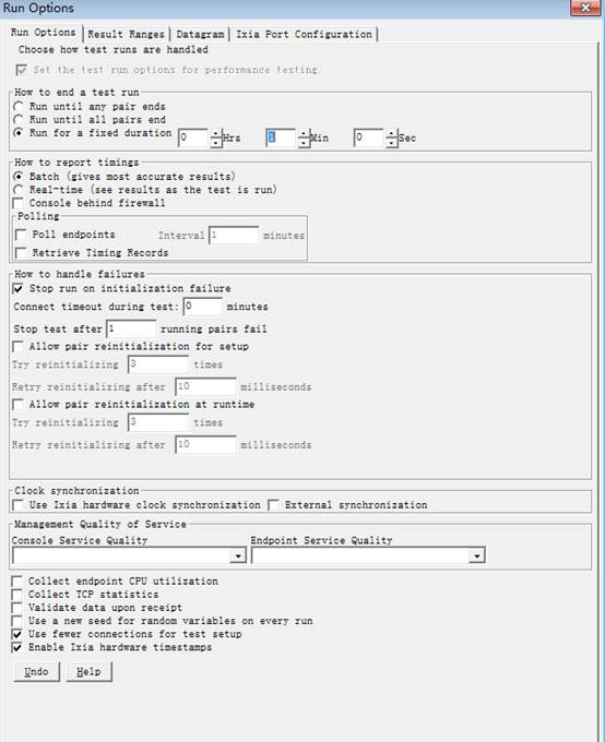
5. Set the test time as 1 min
6. Right click to set the Graph Content as “Groups”
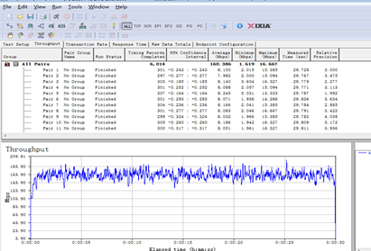
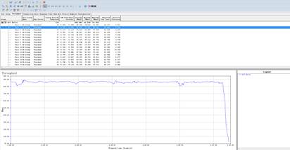
7.Click |
| Expected Result: | The max throughput of the AP radio will be tested
|
| Test Conclusion: |
|


1.2 WiFi6 AP Throughput Performance
| Test Item | WiFi6 AP Throughput Performance |
| Description | Test the AP’s max throughput performance |
| Test Procedure | Topology:
Procedure: 1. Test Environment Check Use a signal scanning tool such as WirelessMon to scan the onsite environment. If the interference from other service set identifiers (SSIDs) is detected, these SSIDs should be turned off; if they cannot be turned off, the test should avoid the channel where a SSID of strong signal interference is located.
Before the test, you can also use WirelessMon to scan the RSSI of the test SSID to ensure that the RSSI is not smaller than –55 dBm. When there is any interference in the test environment, configure the AP channel to the one with the smallest interference. AC#conf AC(config)#ap-config AP840----- The AP name is AP840. AC(config-ap)#channel 64 radio 2 AC(config-ap)#chan-width 80 radio 2 AC(config-ap)#11acsupport enable AC(config-ap)#11axsupport enable AC(config-ap)#end
2. Install IxChariot IxChariot is the industry's leading test tool for simulating real-world applications and assessing network performance in live networks. IxChariot uses distributed, low-profile endpoint to assess point to point performance and network capacity. It can be used to test the highest performance of an AP, thereby obtaining the its upstream and downstream throughput (official website of IxChariot: http://www.ixiacom.com).
Components of IxChariot: ① IxChariot Console: It is installed in the Windows system to generate and simulate traffic, and output the data simulation result. ② Endpoint: It is installed in the Windows system to send and receive traffic.
Step1: Install IxChariot 6.7 (both the Console and Endpoint) on the server. Step2: Install Endpoint on STAs Step3: Start IxChariot
Note: On the server, you should ensure proper running of both the Console and Endpoint, but on an STA, you need to ensure only proper running of the Endpoint.
3. Create a downward data sending stream, and send data from Serve 1.1.1.1 to STA 1.1.1.2. Click
4. Create 20 data streams.
5. Set the test time as 1 min
6. Right click to set the Graph Content as “Groups”
7.Click |
| Expected Result: | The max throughput of the AP radio will be tested
|
| Test Conclusion: |
|


1.3 Multi-Users Throughput Performance
| Test Item | Multi-Users Throughput Performance |
| Description | Test the Multi-Users throughput performance |
| Test Procedure | Topology:
Procedure: 1. Test Environment Check Use a signal scanning tool such as WirelessMon to scan the onsite environment. If the interference from other service set identifiers (SSIDs) is detected, these SSIDs should be turned off; if they cannot be turned off, the test should avoid the channel where a SSID of strong signal interference is located.
Before the test, you can also use WirelessMon to scan the RSSI of the test SSID to ensure that the RSSI is not smaller than –55 dBm.
When there is any interference in the test environment, configure the AP channel to the one with the smallest interference. AC#conf AC(config)#ap-config APXXX----- The AP name is APXXX. AC(config-ap)#channel 149 radio 2 AC(config-ap)#chan-width 80 AC(config-ap)#end
2. Install IxChariot IxChariot is the industry's leading test tool for simulating real-world applications and assessing network performance in live networks. IxChariot uses distributed, low-profile endpoint to assess point to point performance and network capacity. It can be used to test the highest performance of an AP, thereby obtaining the its upstream and downstream throughput (official website of IxChariot: http://www.ixiacom.com).
Components of IxChariot: ① IxChariot Console: It is installed in the Windows system to generate and simulate traffic, and output the data simulation result. ② Endpoint: It is installed in the Windows system to send and receive traffic.
Step1: Install IxChariot 6.7 (both the Console and Endpoint) on the server. Step2: Install Endpoint on STAs Step3: Start IxChariot
Note: On the server, you should ensure proper running of both the Console and Endpoint, but on an STA, you need to ensure only proper running of the Endpoint.
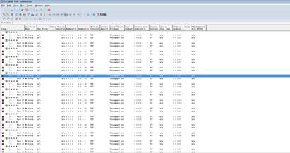
3. Create a downward data sending stream, and send data from Serve 1.1.1.1 to STA 1.1.1.2 -----> 1.1.1.41. Click
4. Create 2 data streams for each user.
5. Set the test time as 1 min
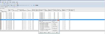
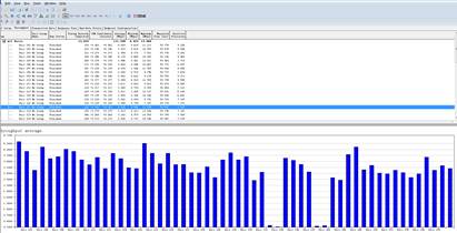
6. Right click to set the Graph Content as “Groups” and “Bar”
7.Click
|
| Expected Result: | The Multi-Users throughput of the AP will be tested
|
| Test Conclusion: |
|


1.4 Multi-Users Video Performance
| Test Item | Multi-Users video performance |
| Description | Test the Multi-Users video performance |
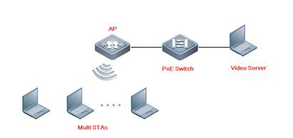
| Test Procedure | Topology:
Procedure: 1. Test Environment Check When there is any interference in the test environment, configure the AP channel to the one with the smallest interference. Radio1 and Radio2 are in a ratio of 1:5, if the device is support Radio3, the scale is 1:5:5. AC#conf AC(config)#ap-config APXXX----- The AP name is APXXX. AC(config-ap)#channel 1 radio 1 AC(config-ap)#chan-width 20 radio 1 AC(config-ap)# sta-limit 5 radio 1 AC(config-ap)#channel 149 radio 2 AC(config-ap)#chan-width 80 radio 1 AC(config-ap)# sta-limit 25 radio 2 AC(config-ap)#end
2. Open all the test devices, connect to the SSID. Check all devices connect succeed with Eweb or CLi command.
3. All STAs access the video on the video server at the same time, record the experience.
4. All STAs access to the video website, access the same video at the same time. |
| Expected Result: | The Multi-Users video performance of the AP will be tested
|
| Test Conclusion: |
|
1.5 Dual 5G Mode Test
| Test Item | Dual 5G Test |
| Description | Test Dual 5G, AP820-L V2 support change the Radio1 to 5G |
| Test Procedure | Topology:
Procedure: 1. Test Environment Check Change the Radio1 to 5G AP#conf AP(config)#interface dot 1/0 AP(config-ap)#radio-type 802.11a AP(config-ap)#chan-width 80 AP(config-ap)#channel 149 AP(config-ap)#exit AP(config)#interface dot 2/0 AP(config-ap)#channel 64 AP(config-ap)#chan-width 80 AP(config-ap)#end
2. Open the WiFi MoHo to check the AP have dual 5G SSID.
3. Connect to the SSID, check the negotiate rate and do the speedtest. |
| Expected Result: | The Radio1 support change to 5G |


 Thank you. We will inform you of our response as soon as possible.