Ruijie Switch PoC Guide (V1.2)


. TestingLists
1.1 Management
1.1.1 Telnet
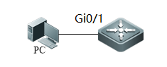
| Testing project: | Telnet |
| Testing purpose: | Enable telnet and log into switch successfully |
| Testing procedure and expected results: |
1. assign IP 192.168.0.1/24 to switch assign IP 192.168.0.2/24 to PC 2. add the following configuration Ruijie(config)#interface VLAN 1 Ruijie(config-if-vlan)#ip address 192.168.0.1 255.255.255.0 Ruijie(config-if-vlan)#exit Ruijie(config)#enable password ruijie Ruijie(config)#line vty 0 4 Ruijie(config-line)#password ruijie Ruijie(config-line)#login Ruijie(config-line)#end Ruijie#wr 3. verify telnet access |
| Measured record: | |
| Testing conclusion: |
|
1.1.2 SSH
| Testing project: | SSH |
| Testing purpose: | Enable SSH and log into switch successfully |
| Testing procedure and expected results: |
1. assign IP 192.168.0.1/24 to switch assign IP 192.168.0.2/24 to PC third-party client networking software must be used such as SecureCRT or PuTTY。 2. add the following configuration Ruijie(config)#interface VLAN 1 Ruijie(config-if-vlan)#ip address 192.168.0.1 255.255.255.0 Ruijie(config-if-vlan)#exit Ruijie(config)#enable service ssh-server Ruijie(config)#crypto key generate dsa Choose the size of the key modulus in the range of 360 to 2048 for your Signature Keys. Choosing a key modulus greater than 512 may take a few minute How many bits in the modulus [512]: //press enter % Generating 512 bit DSA keys ...[ok] Ruijie(config)#line vty 0 4 Ruijie(config-line)#login local Ruijie(config-line)#exit Ruijie(config)#username admin password ruijie Ruijie(config)#enable password ruijie Ruijie(config)#end Ruijie#wr 3. verify SSH access using SecureCRT |
| Measured record: | |
| Testing conclusion: |
|
1.1.3 WEB
| Testing project: | WEB |
| Testing purpose: | Enable WEB and log into switch successfully |
| Testing procedure and expected results: |
1. assign IP 192.168.0.1/24 to switch assign IP 192.168.0.2/24 to PC browser must be IE and other major browsers and open compatible mode. 2. add the following configuration Ruijie(config)#enable service web-server Ruijie(config)#interface vlan 1 Ruijie(config-if)#ip address 192.168.0.1 255.255.255.0 Ruijie(config-if)#exit Ruijie(config)#webmaster level 0 username ruijie password ruijie Ruijie(config)#exit Ruijie#wr 3. verify Web access |
| Measured record: | |
| Testing conclusion: |
|
1.1.4 Syslog
| Testing project: | Syslog |
| Testing purpose: | Configure the logging file name and buffered |
| Testing procedure and expected results: |
1. assign IP 192.168.0.1/24 to switch assign IP 192.168.0.2/24 to PC 2. add the following configuration Ruijie(config)#logging file flash:syslog 7 Ruijie(config)#logging file flash:syslog 131072 Ruijie(config)#logging buffered 131072 Ruijie(config)#logging userinfo Ruijie(config)#logging userinfo command-log 3. Execute command "show log” to display logs in buffer Execute command "dir" privilege EXEC command to check log files in flash Execute command "more flash:syslog.txt" to display logs in flash Execute command "clear logging" privilege EXEC command to clear logs in buffer |
| Measured record: | |
| Testing conclusion: |
|
1.2 Basic Feature
1.2.1 POE
| Testing Project | poe |
| Testing Purpose | Switch can power up AP |
| Testing procedure and expected results: | 1. Power on the Switch, the AP connect to the switch interface.
2. add the following configuration Ruijie(config)#interface gigabitEthernet 0/1 Ruijie(config-if)#poe enable Ruijie(config)#poe mode auto 3. execute “show poe interfaces status” command on switch to check POE power supply status |
| Measured record: | |
| Testing conclusion: |
|
1.2.2 Standard Access Control List
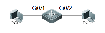
| Testing project: | Standard Access Control List |
| Testing purpose: | Create standard access control list to block access. |
| Testing procedure and expected results: |
1. PC1 and PC2 are in the same vlan assign IP 192.168.0.1/24 to PC1 assign IP 192.168.0.2/24 to PC2 2. add the following configuration Ruijie(config)#ip access-list standard 1 Ruijie(config-std-nacl)#10 deny host 192.168.0.1 Ruijie(config-std-nacl)#20 permit any Ruijie(config-std-nacl)#exit Ruijie(config)#interface gigabitEthernet 0/1 Ruijie(config-if)#ip access-group 1 in Ruijie(config-if)#end Ruijie#wr 3. PC1 ping PC2 Expected results: ping unsuccessfully 4. assign IP 192.168.0.3/24 to PC1 5. PC1 ping PC2 Expected results: ping successfully |
| Measured record: | |
| Testing conclusion: |
|
1.2.3 Extended Access Control List
| Testing project: | Extended Access Control List |
| Testing purpose: | Create standard extended control list to block access. |
| Testing procedure and expected results: |
1. PC1 and PC2 are in the same vlan assign IP 192.168.1.1/24 to PC1 assign IP 192.168.2.2/24 to PC2 2. add the following configuration Ruijie(config)# ip access-list extended 101 Ruijie(config-std-nacl)# 10 deny ip host 192.168.1.1 any Ruijie(config-std-nacl)#20 permit ip any any Ruijie(config-std-nacl)#exit Ruijie(config)#interface gigabitEthernet 0/1 Ruijie(config-if)#ip access-group 101 in Ruijie(config-if)#end Ruijie#wr 3. PC1 ping PC2 Expected results: ping unsuccessfully 4. assign IP 192.168.1.3/24 to PC1 5. PC1 ping PC2 Expected results: ping successfully |
| Measured record: | |
| Testing conclusion: |
|
1.2.4 Expert Access Control List
| Testing project: | Expert Access Control List |
| Testing purpose: | Create expert access control list to block access. |
| Testing procedure and expected results: |
1. PC1 and PC2 are in the same vlan assign IP 192.168.1.1/24 to PC1 assign IP 192.168.1.2/24 to PC2 2. add the following configuration Ruijie(config)#expert access-list extended 2701 Ruijie(config-exp-nacl)#10 deny tcp host 192.168.1.1 any any any eq www Ruijie(config-exp-nacl)#20 permit tcp host 192.168.1.1 any any any eq pop3 Ruijie(config-exp-nacl)#exit Ruijie(config)#interface gigabitEthernet 0/1 Ruijie(config-if)#expert access-group 2701 in Ruijie(config-if)#end Ruijie#wr 3. Start service of web and pop3 on PC2 4. Test web service and pop3 service Expected results: access to web service and pop3 service successfully |
| Measured record: | |
| Testing conclusion: |
|
1.2.5 Time-Based Access ControlList
| Testing project: | Time-Based Access Control List |
| Testing purpose: | Create time-based access control list to block access. |
| Testing procedure and expected results: |
1. PC1 and PC2 are in the same vlan assign IP 192.168.0.1/24 to PC1 assign IP 192.168.0.2/24 to PC2 2. add the following configuration Ruijie(config)#time-range time1 Ruijie(config-time-range)#periodic daily 8:00 to 18:00 Ruijie(config-time-range)#exit Ruijie(config)#ip access-list standard 2 Ruijie(config-std-nacl)#10 permit any time-range time1 Ruijie(config-std-nacl)#20 deny any Ruijie(config-std-nacl)#exit Ruijie(config)#interface gigabitEthernet 0/1 Ruijie(config-if)#ip access-group 2 in Ruijie(config-if)#end Ruijie#wr 3. PC1 ping PC2 Expected results: ping unsuccessfully 4. Change the switch clock at 20 PM Ruijie#clock set 20:37:11 3 16 2007 5. PC1 ping PC2 Expected results: ping successfully |
| Measured record: | |
| Testing conclusion: |
|
1.2.6 DHCP Server
| Testing project: | DHCP Server |
| Testing purpose: | Enable service DHCP and create IP Pool. Test to obtain IP address on computer. |
| Testing procedure and expected results: |
1. add the following configuration Ruijie(config)#service dhcp Ruijie(config)#interface vlan 10 Ruijie(config-if-VLAN 10)#ip address 192.168.1.254 255.255.255.0 Ruijie(config-if-VLAN 10)#exit Ruijie(config)#ip dhcp pool vlan10 Ruijie(dhcp-config)#network 192.168.1.0 255.255.255.0 Ruijie(dhcp-config)#dns-server 218.85.157.99 Ruijie(dhcp-config)#default-router 192.168.1.254 Ruijie(dhcp-config)#exit Ruijie(config)#int range gigabitEthernet 0/1-2 Ruijie(config-if-range)#switchport access vlan 10 Ruijie(config-if)#end Ruijie#wr 2. PC1 and PC2 can obtain IP address. |
| Measured record: | |
| Testing conclusion: |
|
1.2.7 DHCP Relay
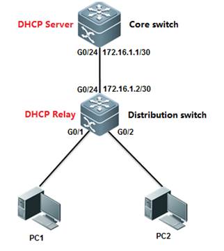
| Testing project: | DHCP Relay |
| Testing purpose: | Enable service DHCP and designated DHCP server IP address. |
| Testing procedure and expected results: |
1. add the following configuration Core switch: Ruijie(config)#interface gigabitEthernet 0/24 Ruijie(config-if-GigabitEthernet 0/24)#no switchport Ruijie(config-if-GigabitEthernet 0/24)#ip address 172.16.1.1 255.255.255.252 Ruijie(config-if-GigabitEthernet 0/24)#exit Ruijie(config)#ip route 192.168.1.0 255.255.255.0 172.16.1.2 Ruijie(config)#service dhcp Ruijie(config)#ip dhcp pool vlan10 Ruijie(dhcp-config)#network 192.168.1.0 255.255.255.0 Ruijie(dhcp-config)#dns-server 218.85.157.99 Ruijie(dhcp-config)#default-router 192.168.1.254 Ruijie(dhcp-config)#end Ruijie#wr
Distribution switch: Ruijie(config)#interface vlan 10 Ruijie(config-if-VLAN 10)#ip address 192.168.1.254 255.255.255.0 Ruijie(config-if-VLAN 10)#exit Ruijie(config)#interface gigabitEthernet 0/24 Ruijie(config-if-GigabitEthernet 0/24)#no switchport Ruijie(config-if-GigabitEthernet 0/24)#ip address 172.16.1.2 255.255.255.252 Ruijie(config-if-GigabitEthernet 0/24)#exit Ruijie(config)#ip route 0.0.0.0 0.0.0.0 172.16.1.1 Ruijie(config)#service dhcp Ruijie(config)#ip helper-address 172.16.1.1 Ruijie(config)#end Ruijie#wr
2. PC1 and PC2 can obtain IP address. |
| Measured record: | |
| Testing conclusion: |
|
1.2.8 Aggregate Port
| Testing project: | Aggregate Port |
| Testing purpose: | Create aggregate port and check the bandwidth of aggregate port. |
| Testing procedure and expected results: |
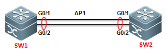
1. add the following configuration SW1>enable SW1#configure terminal SW1(config)#interface range gigabitEthernet 0/1-2 SW1(config-if-range)#port-group 1 SW1(config-if-range)#exit SW1(config)#interface aggregateport 1 SW1(config-if-AggregatePort 1)#switchport mode trunk SW1(config-if-AggregatePort 1)#exit SW1(config)#aggregateport load-balance src-mac SW1(config)#exit SW1#wr
SW2>enable SW2#configure terminal SW2(config)#interface range gigabitEthernet 0/1-2 SW2(config-if-range)#port-group 1 SW2(config-if-range)#exit SW2(config)#interface aggregateport 1 SW2(config-if-AggregatePort 1)#switchport mode trunk SW2(config-if-AggregatePort 1)#exit SW2(config)#aggregateport load-balance src-mac SW2(config)#exit SW2#wr 2. Execute command ‘show int agg 1’ to check the bandwidth of the Aggregate port 1. |
| Measured record: | |
| Testing conclusion: |
|
1.2.9 Multicast
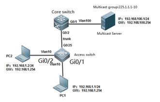
| Testing project: | Multicast |
| Testing purpose: | Enable multicast routing and igmp snooping. |
| Testing procedure and expected results: |
1. add the following configuration
core switch:
Ruijie#configure terminal Ruijie(config)#vlan 10 Ruijie(config-vlan)#vlan 100 Ruijie(config-vlan)#exit Ruijie(config)#ip multicast-routing Ruijie(config)#interface gigabitEthernet 0/1 Ruijie(config-if-GigabitEthernet 0/1)#switchport access vlan 100 Ruijie(config-if-GigabitEthernet 0/1)#exit Ruijie(config)#interface vlan 100 Ruijie(config-if-VLAN 100)#ip address 192.168.100.254 255.255.255.0 Ruijie(config-if-VLAN 100)#ip pim dense-mode Ruijie(config)#interface vlan 10 Ruijie(config-if-VLAN 10)#ip address 192.168.10.254 255.255.255.0 Ruijie(config-if-VLAN 10)#ip pim dense-mode Ruijie(config-if-VLAN 10)#exit Ruijie(config)#interface gigabitEthernet 0/2 Ruijie(config-if-GigabitEthernet 0/2)#switchport mode trunk Ruijie(config-if-GigabitEthernet 0/2)#exit Ruijie(config)#end Ruijie#wr
Access switch:
Ruijie(config)#vlan 10 Ruijie(config-vlan)#exit Ruijie(config)#interface gigabitEthernet 0/25 Ruijie(config-if-GigabitEthernet 0/25)#switchport mode trunk Ruijie(config-if-GigabitEthernet 0/25)#exit Ruijie(config)#interface range gigabitEthernet 0/1-2 Ruijie(config-if-range)#switchport access vlan 10 Ruijie(config-if-range)#exit Ruijie(config)#ip igmp snooping ivgl Ruijie(config)#ip igmp snooping vlan 10 mrouter interface g0/25 Ruijie(config)#end Ruijie(config)#ip igmp profile 1 Ruijie<config-profile>#permit Ruijie<config-profile>#range 225.1.1.1 225.1.1.10 Ruijie<config-profile>#exit Ruijie(config)#interface range gigabitEthernet 0/1-2 Ruijie(config-if-range)#ip igmp snooping filter 1 Ruijie(config-if-range)#exit Ruijie(config)#ip igmp snooping fast-leave enable Ruijie(config)#ip igmp snooping suppression enable Ruijie(config)#end Ruijie#wr
2. Execute command ‘show ip igmp snooping gda-table’ to display IGMP Snooping table on access switch 3. Execute command ‘show ip igmp snooping statistics ’ to display IGMP Snooping statistics |
| Measured record: | |
| Testing conclusion: |
|
1.3 Security Features
1.3.1 Port Security
| Testing project: | Port Security |
| Testing purpose: | Enable port security, bind IP address and mac address to test the connection |
| Testing procedure and expected results: | 1. assign IP 192.168.0.1/24 to PC1 assign IP 192.168.0.2/24 to PC2 The MAC address of PC1 is “00:f0:4c:87:19:1e” Both PC1 and PC2 are in vlan 1 2. add the following configuration Ruijie(config)#interface gigabitEthernet 0/1 Ruijie(config-if)#switchport port-security binding 00f0.4c87.191e vlan 1 192.168.0.1 Ruijie(config-if)#switchport port-security Ruijie(config-if)#end Ruijie#wr 3. PC1 ping PC2 Expected results: ping successfully 4. Change the ip address or mac-address of PC1 Expected results: ping unsuccessfully |
| Measured record: | |
| Testing conclusion: |
|
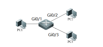
1.3.2 Port Protect
| Testing project: | Port Protect |
| Testing purpose: | Enable port protect, then test the connection between different ports |
| Testing procedure and expected results: |
1. assign IP 192.168.0.1/24 to PC1 assign IP 192.168.0.2/24 to PC2 assign IP 192.168.0.3/24 to PC3 2. add the following configuration Ruijie(config)#interface gigabitEthernet 0/1 Ruijie(config-if)#switchport protected Ruijie(config)#interface gigabitEthernet 0/2 Ruijie(config-if)#switchport protected 3. PC1 ping PC2 Expected results: ping unsuccessfully 4. PC1 ping PC3 Expected results: ping successfully 5. PC2 ping PC3 Expected results: ping successfully |
| Measured record: | |
| Testing conclusion: |
|
1.3.3 IP Source Guard
| Testing project: | IP Source Guard |
| Testing purpose: | Enable IP source guard and change IP address for testing |
| Testing procedure and expected results: |
1. PC MAC:0000:0100:0001 The MAC address of PC1 is “0000-0100-0001” DHCP Pool : 10.1.1.100-200/24 2. add the following configuration Ruijie(config)#ip dhcp snooping Ruijie(config)#ip source binding 0000.0100.0001 vlan 1 10.1.1.10 interface gigabitEthernet 0/1 Ruijie(config)#interface gigabitEthernet 0/1 Ruijie(config-if)# ip verify source port-security Ruijie(config)#interface gigabitEthernet 0/2 Ruijie(config-if)# ip dhcp snooping trust Ruijie(config-if)#end Ruijie#wr 3. PC ping DHCP Server after obtaining IP address Expected results: ping successfully 4. PC ping DHCP Server after changing the address as 10.1.1.10 Expected results: ping successfully 5. PC ping DHCP Server after changing the address Expected results: ping unsuccessfully |
| Measured record: | |
| Testing conclusion: |
|

1.3.4 DHCP Snooping
| Testing project: | DHCP Snooping |
| Testing purpose: | Enable DHCP snooping and make the PC obtain the correct IP address |
| Testing procedure and expected results: |
1. assign IP 192.168.0.2/24 to PC2(DHCP Server) 2. Enable DHCP Snooping Ruijie(config)#ip dhcp snooping 3. DHCP client PC1 are obtaining IP address (ipconfig/renew) Expected results: PC1 obtains IP unsuccessfully 4. Configure the port connected to DHCP server as DHCP Snooping trusted port. Ruijie(config)#int Gi0/2 Ruijie(config-if)#ip dhcp snooping trust 5. DHCP client PC1 are obtaining IP address (ipconfig/renew) Expected results: PC1 obtains IP successfully, login switch, excute “show ip dhcp snooping binding” to check the DHCP snooping table |
| Measured record: | |
| Testing conclusion: |
|
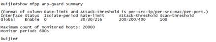
1.3.5 NFPP
| Testing project: | NFPP |
| Testing purpose: | Enable NFPP and check the threshold |
| Testing procedure and expected results: |
1. add the following configuration Ruijie(config)#nfpp Ruijie(config-nfpp)#arp-guard rate-limit per-port 256 Ruijie(config-nfpp)# arp-guard rate-limit per-src-mac 30 Ruijie(config-nfpp)# arp-guard rate-limit per-src-ip 30 Ruijie(config-nfpp)#end Ruijie#wr 2. Check the threshold of NFPP Ruijie#show nfpp arp-guard summary
|
| Measured record: | |
| Testing conclusion: |
|
1.4 Redundancy
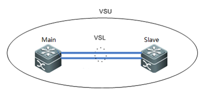
1.4.1 VSU
| Testing project: | VSU |
| Testing purpose: | Enable VSU and check the status of VSU |
| Testing procedure and expected results: |
1. Prepare 4*10G optical module and 2 optical fiber as the VSL 2. Add the following configuration
Main switch
Switch1(config)# switch virtual domain 1 Switch1(config-vs-domain)# switch 1 Switch1(config-vs-domain)# switch 1 priority 200 ------>Priority is 100 by default , switch with the higher priority becomes the active chassis Switch1(config-vs-domain)# exit Switch1(config)#vsl-port ------>VSL is the heartbeat and traffic channel between 2 VSU members. You must configure at least 2 pair of VSL Switch1(config-vsl-port)#port-member interface TenGigabitEthernet 0/25 Switch1(config-vsl-port)#port-member interface TenGigabitEthernet 0/26 Switch1(config-vsl-port)#exit
Slave switch
Switch2(config)# switch virtual domain 1 ------>domain ID must be the same to that of active chassis Switch2(config-vs-domain)# switch 2 ------>switch ID must be different from that of active chassis Switch2(config-vs-domain)# switch 2 priority 150 Switch2(config-vs-domain)# exit Switch2(config)#vsl-port ------>VSL is the heartbeat and traffic channel between 2 VSU members. You must configure at least 2 pair of VSL Switch2(config-vsl-port)#port-member interface TenGigabitEthernet 0/25 Switch2(config-vsl-port)#port-member interface TenGigabitEthernet 0/26 3. Connect VSL cable and confirm that links come up 4. Save configuration and convert both VSU members to virtual mode at the same time 5. Add the following configuration
Main switch
Switch1# wr Switch1# switch convert mode virtual ------>convert switch working mode from standalone mode to virtual mode Are you sure to convert switch to virtual mode[yes/no]:yes Do you want to recovery“config.text”from“virtual_switch.text”[yes/no]:no
Slave switch
Switch2#wr Switch2# switch convert mode virtual Are you sure to convert switch to virtual mode[yes/no]:yes Do you want to recovery“config.text”from“virtual_switch.text”[yes/no]:no 6. Both VSU members reloads automatically 7. Execute command " show switch virtual" to display status of VSU. 8. Execute command " show switch virtual link" to display status of VSL. 9. Execute command " show switch virtual role" to display roles of VSU. 10. Execute command " show switch virtual config" to display configurations of VSU. |
| Measured record: | |
| Testing conclusion: |
|
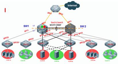
1.4.2 VRRP+MSTP
| Testing project: | VRRP+MSTP |
| Testing purpose: | Enable MSTP and VRRP, check the status of MSTP and VRRP |
| Testing procedure and expected results: |
1. SW1 is the master VRRP gateway for users on all vlans, and SW2 is the backup VRRP gateway for users on all vlans. Connect SW1 and SW2 through an Aggregate port to ensure reliability and configure this AP as Trunk port. 2. The IP address of SW1 on VLANs from 10 to 80 are 192.168.10.1 to 192.168.80.1 , and IP address of SW2 on VLANs from 10 to 80 are 192.168.10.2 to 192.168.80.2 , and VRRP IP address are 192.168.10.254 to 192.168.80.254. 3. Add the following configuration
Configuring SW1
Ruijie#config terminal Ruijie(config)#spanning-tree mst 0 priority 0 ------>instance id=0 , priority=0(The lower the number, the more likely the switch will be chosen as the root bridge) by default , all vlans are mapped to instance 0 . Ruijie(config)#spanning-tree ------>enable STP feature and the default STP mode is MSTP Ruijie(config)#interface aggregateport 1 Ruijie(config-if-AggregatePort 1)#switchport mode trunk Ruijie(config-if-AggregatePort 1)#exit Ruijie(config)#interface tengigabitEthernet 3/1 Ruijie(config-if-TenGigabitEthernet 3/1)#port-group 1 Ruijie(config-if-TenGigabitEthernet 3/1)#exit Ruijie(config)#interface tengigabitEthernet 3/2 Ruijie(config-if-TenGigabitEthernet 3/2)#port-group 1 Ruijie(config-if-TenGigabitEthernet 3/2)#exit Ruijie(config)#interface range gigabitEthernet 1/1-5 Ruijie(config-if-range)#switchport mode trunk ----->don't forget to prune trunk port Ruijie(config-if-range)#exit Ruijie(config)#vlan 10 Ruijie(config)#inter vlan 10 Ruijie(config-if-VLAN 10)#ip address 192.168.10.1 255.255.255.0 Ruijie(config-if-VLAN 10)#vrrp 10 ip 192.168.10.254 Ruijie(config-if-VLAN 10)#vrrp 10 priority 120 ------> vrrp group id=10 , priority value=120 (the bigger the number , the more likely the switch will be chosen as the master ,and default value is 100) Ruijie(config-if-VLAN 10)#exit Ruijie(config)#vlan 20 Ruijie(config)#inter vlan 20 Ruijie(config-if-VLAN 20)#ip address 192.168.20.1 255.255.255.0 Ruijie(config-if-VLAN 20)#vrrp 20 ip 192.168.20.254 Ruijie(config-if-VLAN 20)#vrrp 20 priority 120 Ruijie(config-if-VLAN 20)#exit
...........configuration of VLAN 30 ~ VLAN 70 are omitted............
Ruijie(config)#vlan 80 Ruijie(config)#inter vlan 80 Ruijie(config-if-VLAN 80)#ip address 192.168.80.1 255.255.255.0 Ruijie(config-if-VLAN 80)#vrrp 80 ip 192.168.80.254 Ruijie(config-if-VLAN 80)#vrrp 80 priority 120 Ruijie(config-if-VLAN 80)#end Ruijie#wr
Configuring SW2
Ruijie#config terminal Ruijie(config)#spanning-tree mst 0 priority 4096 ------>instance id=0 , priority=4096(The lower the number, the more likely the switch will be chosen as the root bridge) by default , all vlans are mapped to instance 0 Ruijie(config)#spanning-tree ------>enable STP feature and default mode is MSTP Ruijie(config)#interface aggregateport 1 Ruijie(config-if-AggregatePort 1)#switchport mode trunk Ruijie(config-if-AggregatePort 1)#exit Ruijie(config)#interface tengigabitEthernet 3/1 Ruijie(config-if-TenGigabitEthernet 3/1)#port-group 1 Ruijie(config-if-TenGigabitEthernet 3/1)#exit Ruijie(config)#interface tengigabitEthernet 3/2 Ruijie(config-if-TenGigabitEthernet 3/2)#port-group 1 Ruijie(config-if-TenGigabitEthernet 3/2)#exit Ruijie(config)#interface range gigabitEthernet 1/1-5 Ruijie(config-if-range)#switchport mode trunk ----->don't forget to prune trunk port Ruijie(config)#vlan 10 Ruijie(config)#inter vlan 10 Ruijie(config-if-VLAN 10)#ip address 192.168.10.2 255.255.255.0 Ruijie(config-if-VLAN 10)#vrrp 10 ip 192.168.10.254 ------>vrrp group id=10 , priority value remains default setting(the bigger the number , the more likely the switch will be chosen as the master ,and default value is 100) Ruijie(config-if-VLAN 10)#exit
Ruijie(config)#vlan 20 Ruijie(config)#inter vlan 20 Ruijie(config-if-VLAN 20)#ip address 192.168.20.2 255.255.255.0 Ruijie(config-if-VLAN 20)#vrrp 20 ip 192.168.20.254 Ruijie(config-if-VLAN 20)#exit
...........configuration of VLAN 30 ~ VLAN 70 are omitted............ Ruijie(config)#vlan 80 Ruijie(config)#inter vlan 80 Ruijie(config-if-VLAN 80)#ip address 192.168.80.2 255.255.255.0 Ruijie(config-if-VLAN 80)#vrrp 80 ip 192.168.80.254 Ruijie(config-if-VLAN 80)#end Ruijie#wr
Configuring SW11,SW12,S13,S14,S15,S16
Ruijie#config terminal Ruijie(config)#interface range gigabitEthernet 0/25-26 Ruijie(config-if-range)#switchport mode trunk Ruijie(config-if-range)#exit
Ruijie(config)#spanning-tree ------>enable STP feature and default mode is MSTP Ruijie(config)#exit Ruijie#wr 4. Execute command " show spanning-tree" to display status of MSTP. 5. Execute command " show vrrp brief" to display status of VRRP. 6. Execute command "show spanning-tree summary " to display summary information of MSTP. |
| Measured record: | |
| Testing conclusion: |
|
1.5 Authentication
1.5.1 Dot1X authentication
| Testing project: | Dot1X authentication |
| Testing purpose: | Enable Dot1X authentication and the terminal can pass the authentication to access to Internet. |
| Testing procedure and expected results: |
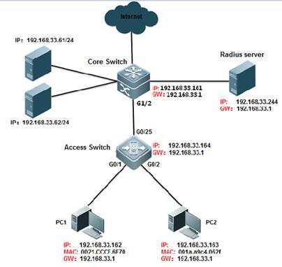
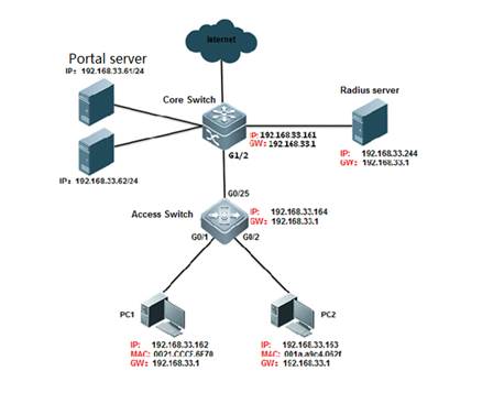
1. Assign ip to the device according to the picture. 2. add the following configuration
Basic dot1x configuration
Ruijie(config)#aaa new-model ------>turn on aaa switch Ruijie(config)#radius-server host 192.168.33.244 ------>configure radius server Ruijie(config)#radius-server key ruijie ------>configure radius key Ruijie(config)#aaa authentication dot1x ruijie group radius none ------> Define an IEEE802.1x authentication method list. Ruijie(config)#aaa accounting network ruijie start-stop group radius ------> Define the AAA network accounting method list. Ruijie(config)#aaa accounting update periodic 15 ------> Set the account update function. Ruijie(config)#dot1x authentication ruijie ------> 802.1X to select the authentication method list Ruijie(config)#dot1x accounting ruijie ------> 802.1X to select the accounting method list Ruijie(config)#interface gigabitEthernet 1/2 Ruijie(config-if-GigabitEthernet 1/2)#switchport mode trunk Ruijie(config-if-GigabitEthernet 1/2)#dot1x port-control auto ------> Enable 802.1X authentication on the interface Ruijie(config-if-GigabitEthernet 1/2)#ip add 192.168.33.161 255.255.255.0 ------> configure switch ip address Ruijie(config-if-GigabitEthernet 1/2)#end Ruijie#write ------> save configuration
Enable the secure channel function
Ruijie(config)#expert access-list extended ruijie Ruijie(config-exp-nacl)#permit arp any any any any any ------>make the ip and arp packets free authentication Ruijie(config-exp-nacl)#permit ip any any host 192.168.33.61 any ------> To allow access to the home page of the site before authentication Ruijie(config-exp-nacl)#permit ip any any host 192.168.33.62 any ------> To allow access to the home page of the site before authentication Ruijie(config-exp-nacl)#permit ip any any host 192.168.33.244 any ------> To allow access to the home page of the site before authentication Ruijie(config-exp-nacl)#permit host 192.168.33.163 host 001a.a9c4.062f any any ------> This host implements authentication free Ruijie(config-exp-nacl)#exit Ruijie(config)#security global access-group ruijie
Smp server configuration
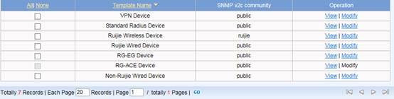
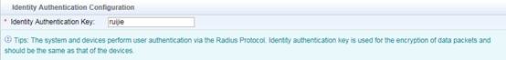
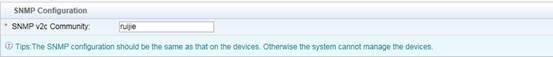
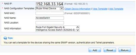
Edit SMP device template first , go to Authentication & Authority > Device > NAS Configuration Templates , modify Ruijie Wired Device , set the parameters as below ,
Identity Authentication Key is used for Radius Server.
SNMP community is used for SNMP management.
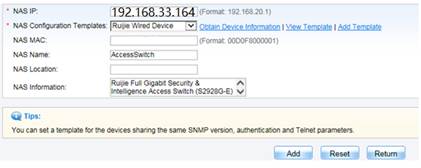
Click Modify when complete setting . Go to Authentication & Authority > Device > Add , input NAS IP address , select Device Template , System will get relevant information via SNMP automatically. Click Add to finish.
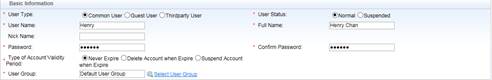
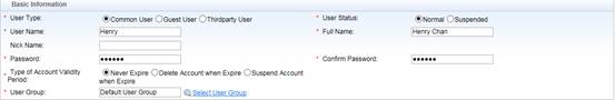
Go to Authentication & Authority > User > Add , fill in required fields , here we create a user named “Henry” and put it into Default User Group. Common User indicates it is a SMP local user account.
3. verify dot1x authenticate. 4. Execute command "show dot1x summary " to display summary information of dot1x authentication. |
| Measured record: | |
| Testing conclusion: |
|
1.5.2 WEB authentication
| Testing project: | WEB authentication |
| Testing purpose: | Enable WEB authentication and the terminal can pass the authentication to access to Internet. |
| Testing procedure and expected results: |
1. Assign ip to the device according to the picture. 2. add the following configuration Ruijie#configure terminal Ruijie(config)#aaa new-model Ruijie(config)#aaa authentication web-auth default group radius Ruijie(config)#aaa accounting net-work default start-stop group radius Ruijie(config)#radius-server host 192.168.33.244 Ruijie(config)#radius-server key ruijie Ruijie(config)#web-auth template eportalv2 Ruijie(config-tmplt-v2)#ip 192.158.33.61 Ruijie(config-tmplt-v2)#url http://192.168.33.61:8080/eportal/index.jsp Ruijie(config-tmplt-v2)#exit Ruijie(config)#interface Gi1/2 Ruijie(config-if)#web-auth enable eportalv2 Ruijie(config-if)#end Ruijie#wr
Smp server configuration
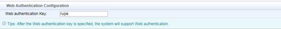
Edit SMP device template first , go to Authentication & Authority > Device > NAS Configuration Templates , modify Ruijie Wired Device , set the parameters as below ,
Identity Authentication Key is used for Radius Server.
Web Authentication Key is used for Web Portal.
SNMP community is used for SNMP management.
Click Modify when complete setting . Go to Authentication & Authority > Device > Add , input NAS IP address , select Device Template , System will get relevant information via SNMP automatically. Click Add to finish.
Go to Authentication & Authority > User > Add , fill in required fields , here we create a user named “Henry” and put it into Default User Group. Common User indicates it is a SMP local user account.
3. verify WEB authenticate. 4. Execute command "show web-auth user all " to display user information of WEB authentication. |
| Measured record: | |
| Testing conclusion: |
|


 Thank you. We will inform you of our response as soon as possible.